Mase Generators IS 2500 User manual

1
M.OFF.IS2500
22/10/01
MANUALE DI SERVIZIO
SERVICEMANUAL
IS 2500
IS 3500/3501
IS 4500/4501
IS 5500/5501

2

3
INDICEINDICE
INDICEINDICE
INDICE
1 CARATTERISTI CHE TECNICHE1 CARATTERISTI CHE TECNICHE
1 CARATTERISTI CHE TECNICHE 1 TECHNICAL FEATURES1 TECHNICAL FEATURES
1 TECHNICAL FEATURES1 TECHNICAL FEATURES
1 TECHNICAL FEATURES
1.11.1
1.11.1
1.1 Engine
Alternator
Dimensions
1.21.2
1.21.2
1.2 Identification of generator
Generator serial number
Engine serial number
1.31.3
1.31.3
1.3 Identification of components
1.41.4
1.41.4
1.4 Control panel
22
22
2Engine
33
33
3Principle of power generation
44
44
4ServiceService
ServiceService
Service
4.14.1
4.14.1
4.1 Excitation winding
4.24.2
4.24.2
4.2 Power excitation
4.34.3
4.34.3
4.3 Battery charger winding
4.44.4
4.44.4
4.4 Battery charger fuse
4.54.5
4.54.5
4.5 Alternator thermostat
4.64.6
4.64.6
4.6 Rotor winding
4.74.7
4.74.7
4.7 Rotor diode
4.84.8
4.84.8
4.8 Capacitor
4.94.9
4.94.9
4.9 Printed circuit relay
4.9.14.9.1
4.9.14.9.1
4.9.1 Fuse
4.9.24.9.2
4.9.24.9.2
4.9.2 Relay
4.9.34.9.3
4.9.34.9.3
4.9.3 Diode 1000V 1A
4.9.44.9.4
4.9.44.9.4
4.9.4 Diode 600V 6A
4.9.54.9.5
4.9.54.9.5
4.9.5 Printed circuit
4.9.64.9.6
4.9.64.9.6
4.9.6 Heat exchanger
4.9.74.9.7
4.9.74.9.7
4.9.7 Zinc anodes
4.9.84.9.8
4.9.84.9.8
4.9.8 Stop solenoid
4.9.94.9.9
4.9.94.9.9
4.9.9 Diesel pump
4.9.104.9.10
4.9.104.9.10
4.9.10 Water temperature switch
4.9.114.9.11
4.9.114.9.11
4.9.11 Oil pressure switch
4.9.124.9.12
4.9.124.9.12
4.9.12 A.T.T. Device
4.9.134.9.13
4.9.134.9.13
4.9.13 Starter
4.9.144.9.14
4.9.144.9.14
4.9.14Belt of the water pump
4.9.154.9.15
4.9.154.9.15
4.9.15 Water pump
4.9.164.9.16
4.9.164.9.16
4.9.16Engine speed adjustment
55
55
5Trouble shooting table
66
66
6Wiring diagram
1.11.1
1.11.1
1.1 Motore
Alternatore
Dimensioni
1.21.2
1.21.2
1.2 Identificazione del generatore
Numero matricola del generatore
numero matricola del motore
1.31.3
1.31.3
1.3 Identificazione dei componenti
1.41.4
1.41.4
1.4 Cruscotto comandi
22
22
2Motore
33
33
3Principio di funzionamento
44
44
4ControlliControlli
ControlliControlli
Controlli
4.14.1
4.14.1
4.1 Avvolgimento di eccitazione
4.24.2
4.24.2
4.2 Avvolgimento di potenza
4.34.3
4.34.3
4.3 Avvolgimento di carica batteria
4.44.4
4.44.4
4.4 Fusibile carica batteria
4.54.5
4.54.5
4.5 Interruttore termico
4.64.6
4.64.6
4.6 Avvolgimento di rotore
4.74.7
4.74.7
4.7 Diodi di rotore
4.84.8
4.84.8
4.8 Condensatore
4.94.9
4.94.9
4.9 Scheda rele'
4.9.14.9.1
4.9.14.9.1
4.9.1 Fusibile
4.9.24.9.2
4.9.24.9.2
4.9.2 Rele'
4.9.34.9.3
4.9.34.9.3
4.9.3 Diodi 1000V 1A
4.9.44.9.4
4.9.44.9.4
4.9.4 Diodi 600V 6A
4.9.54.9.5
4.9.54.9.5
4.9.5 Circuito stampato
4.9.64.9.6
4.9.64.9.6
4.9.6 Scambiatore di calore
4.9.74.9.7
4.9.74.9.7
4.9.7 Anodo di zinco
4.9.84.9.8
4.9.84.9.8
4.9.8 Elettrovalvola
4.9.94.9.9
4.9.94.9.9
4.9.9 Pompa gasolio
4.9.104.9.10
4.9.104.9.10
4.9.10 Termostato acqua
4.9.114.9.11
4.9.114.9.11
4.9.11 Pressostato olio
4.9.124.9.12
4.9.124.9.12
4.9.12 Sonda A.T.T.
4.9.134.9.13
4.9.134.9.13
4.9.13 Motorino avviamento
4.9.144.9.14
4.9.144.9.14
4.9.14Cinghia pompa acqua
4.9.154.9.15
4.9.154.9.15
4.9.15 Pompa acqua
4.9.164.9.16
4.9.164.9.16
4.9.16Regolazione dei giri
55
55
5Tabella guasti
66
66
6Schema elettrico

4
1)CARATTERISTICHE TECNICHE - TECHNICAL FEATURES1)CARATTERISTICHE TECNICHE - TECHNICAL FEATURES
1)CARATTERISTICHE TECNICHE - TECHNICAL FEATURES
Monocilindrico a scoppio 4 tempi
diesel raffreddato ad aria
MOTOREMOTORE
MOTOREMOTORE
MOTORE
Cilindrata
Modello
Giri/minuto
Alesaggio per corsa
Potenza Hp
Consumo g./Hp.h
Alimentazione
Sistema di avviamento
Capacita' olio
Inclinazione massima
ALTERNATOREALTERNATORE
ALTERNATORE
Sincrono,monofase,autoeccitato,
due poli,senza spazzole
Potenza continua
Fattore di potenza
Classe isolamento
Frequenza Hz
DIMENSIONIDIMENSIONI
DIMENSIONI
Lunghezza
Larghezza
Altezza
Peso
R.P.M.
Bore for stroke
Power Hp
Fuel consumption g./Hp.h
Fuel
Starting system
Oil capacity
Max inclination
Synchronous, self-excited,
single phase, 2 poles,brushless
Continuous output
Power factor
Insulation class
Frequecy Hz
Lenght
Width
Height
Weight
Model
ALTERNATORALTERNATOR
ALTERNATOR
DIMENSIONDIMENSION
DIMENSIONDIMENSION
DIMENSION
DIESEL DIESEL DIESEL
ELETTRICO ELETTRICO ELETTRICO
20° 20° 20°
1 1 1
F F F
509mm 660mm 720mm
1.1)MOTORE - ALTERNATORE - DIMENSIONI ENGINE - ALTERNATOR - DIMENSION1.1)MOTORE - ALTERNATORE - DIMENSIONI ENGINE - ALTERNATOR - DIMENSION
1.1)MOTORE - ALTERNATORE - DIMENSIONI ENGINE - ALTERNATOR - DIMENSION
1cylinder,4 stroke,internal
combustion air-cooled diesel
ENGINEENGINE
ENGINEENGINE
ENGINE Yanmar Yanmar Yanmar
Displacement
L48 AE L70AE L100AE
3,8/4,2 4,2/4,7 5,5/6,1 6,0/6,7 7,7/8,8 9/10
220 230 220 230 220 230
0,8 lt. 1,1 lt. 1,1 lt.
70 X 55 78 X 62 86 X 70
211cc. 296 cc. 406 cc.
65Kg 78Kg 110Kg
445mm 545mm 565mm
406mm 460mm 490mm
1700W 1900W 2700W 2900W 4000W 4800W
50 60 50 60 50 60
3000 3600 3000 3600 3000 3600

5
1.2) IDENTIFICAZIONE DEL GENERATORE - IDENTIFICATION OF GENSET1.2) IDENTIFICAZIONE DEL GENERATORE - IDENTIFICATION OF GENSET
1.2) IDENTIFICAZIONE DEL GENERATORE - IDENTIFICATION OF GENSET
Il numero di matricola del generatore e'
riportato su di un targhetta metallica
rivettata sulla parte inferiore della cassa
(Fig.A).
Qualora non sia possibile identificare il
generatore da questo numero, si faccia
riferimento al numero di matricola del mo-
tore, punzonato sul basamento (Fig.B).
Each generator has an identification
numberimpressedonasmallmetallicplate
and rivetted to the lower front side of the
sound shield (Fig.A).
Incaseidentifyingbythisnumberbecomes
impossible,pleasenotetheenginenumber,
die stamped on the crankcase (Fig.B)
Fig.AFig.A
Fig.AFig.A
Fig.A Fig.BFig.B
Fig.BFig.B
Fig.B

6
1.3) IDENTIFICAZIONE DEI COMPONENTI - IDENTIFICATION OF COMPONENTS1.3) IDENTIFICAZIONE DEI COMPONENTI - IDENTIFICATION OF COMPONENTS
1.3) IDENTIFICAZIONE DEI COMPONENTI - IDENTIFICATION OF COMPONENTS
Elementi della macchina (Fig.5)Elementi della macchina (Fig.5)
Elementi della macchina (Fig.5)
1)1)
1)1)
1) MOTORE
2)2)
2)2)
2) ALTERNATORE
3)3)
3)3)
3) CRUSCOTTO ALTERNATORE
4)4)
4)4)
4) ELETTROVALVOLA DI ARRESTO
5)5)
5)5)
5) POMPA ACQUA
6)6)
6)6)
6) RITORNO COMBUSTIBILE
7)7)
7)7)
7) LEVA ARRESTO MANUALE
8)8)
8)8)
8) ASTA LIVELLO OLIO
9)9)
9)9)
9) POMPACOMBUSTIBILE
10)10)
10)10)
10) INGRESSO COMBUSTIBILE
11)11)
11)11)
11) INGRESSO TUBAZIONE ACQUA
12)12)
12)12)
12) PRESA ARIA
13)13)
13)13)
13) INGRESSO CAVI ELETTRICI
14)14)
14)14)
14) INGRESSO ACQUA
15)15)
15)15)
15) TAPPO CARICO OLIO
16)16)
16)16)
16) SCAMBIATORE DI CALORE
17)17)
17)17)
17) TERMOSTATO ACQUA
18)18)
18)18)
18) PRESSOSTATO OLIO
Generator components (Fig.5)Generator components (Fig.5)
Generator components (Fig.5)
1)1)
1)1)
1) ENGINE
2)2)
2)2)
2) ALTERNATOR
3)3)
3)3)
3) ALTERNATOR CONTROL PANEL
4)4)
4)4)
4) FUEL SOLENOID
5)5)
5)5)
5) WATER PUMP
6)6)
6)6)
6) FUEL RETURN
7)7)
7)7)
7) STOP LEVEL
8)8)
8)8)
8) DEEP STICK OIL
9)9)
9)9)
9) FUEL PUMP
10)10)
10)10)
10) FUEL FEED
11)11)
11)11)
11) INPUT WATER CONNECTIONS
12)12)
12)12)
12) AIR INLET
13)13)
13)13)
13) INLET ELETTRIC CONNECTIONS
14)14)
14)14)
14) INLET WATER
15)15)
15)15)
15) OIL FILLING WP
16)16)
16)16)
16) HEAT EXCHANGER
17)17)
17)17)
17) WATER TEMPERATURE SWITCH
18)18)
18)18)
18) OIL PRESSURE SWITCH

7
1.4)CRUSCOTTO COMANDI1.4)CRUSCOTTO COMANDI
1.4)CRUSCOTTO COMANDI
1)1)
1)1)
1) CONTAORE
2)2)
2)2)
2) PULSANTE OFF
3)3)
3)3)
3) PULSANTE START
4)4)
4)4)
4) PULSANTE ON
5)5)
5)5)
5) LED PANNELLO ON (VERDE)
6)6)
6)6)
6) LED USCITA GENERATORE (VERDE)
7)7)
7)7)
7) LED PRESSIONE OLIO (ROSSO)
8)8)
8)8)
8) LED TEMPERATURA MOTORE (ROSSO)
9)9)
9)9)
9)LED TEMPERATURA GENERATORE(ROSSO)
1.4) CONTROL PANEL1.4) CONTROL PANEL
1.4) CONTROL PANEL
1)1)
1)1)
1) HOURSMETER
2)2)
2)2)
2) OFF BUTTON
3)3)
3)3)
3) START BUTTON
4)4)
4)4)
4) BUTTON ON
5)5)
5)5)
5) PANEL ON LED (GREEN)
6)6)
6)6)
6) GENERATOR OUTPUT LED (GREEN)
7)7)
7)7)
7) OIL PRESSURE LED (RED)
8)8)
8)8)
8) ENGINE TEMPERATURE LED (RED)
9)9)
9)9)
9) GENERATOR TEMPERATURE LED (RED)

8
2) MANUTENZIONE2) MANUTENZIONE
2) MANUTENZIONE
Per la durata e il corretto funzionamento del
generatoreènecessariorispettareilprogramma
dicontrolliemanutenzioneindicatinellatabella
seguente.
L'esecuzione di queste operazioni è descritta,
perla parte relativaal motore, sullibretto uso e
manutenzione o sul manuale d'officina del
costruttore del motore.
Siricordainoltre chedurantele normali opera-
zioni di manutenzione (Montaggio/smontag-
gio)ènecessariorispettarealcuneregolegene-
rali,quindi:
- rispettare le coppie di serraggio.
-utilizzare grassi,olii, frenafilettiappropriati.
-non lavare avvolgimentioparti elettrichecon
acidi o sostanze corrosive.
- spruzzare disossidanti sui contatti elettrici
- rispettare la
numerazione
deicavi.
Se necessario
annotarne la
numerazionee
laposizione.
2) MAINTENANCE2) MAINTENANCE
2) MAINTENANCE
For the longevity and correct performance of
the generator, it is necessary to respect the
checkandmaintenanceprogramdetailedoutin
thefollowingtables.
As regarding the engine, the maintenance op-
erations are described in the use and mainte-
nance manual and the workshop manual pre-
pared by the engine manufacturer.
Please note further that while involved in nor-
mal maintenance work of the generator (Dis-
mounting/mounting)certaingeneralrulesmust
be adhered to:
- respect the torque specifications.
-useappropriateoil,greaseandbondingagents.
- do not clean windings or electrical parts with
acid or other corroding substances.
- spray deoxidizer on the electrical contact
points
- respect the
numerical or-
der of wires
If necessary,
note their nu-
meration and
position.

9
22
22
2
11
11
1
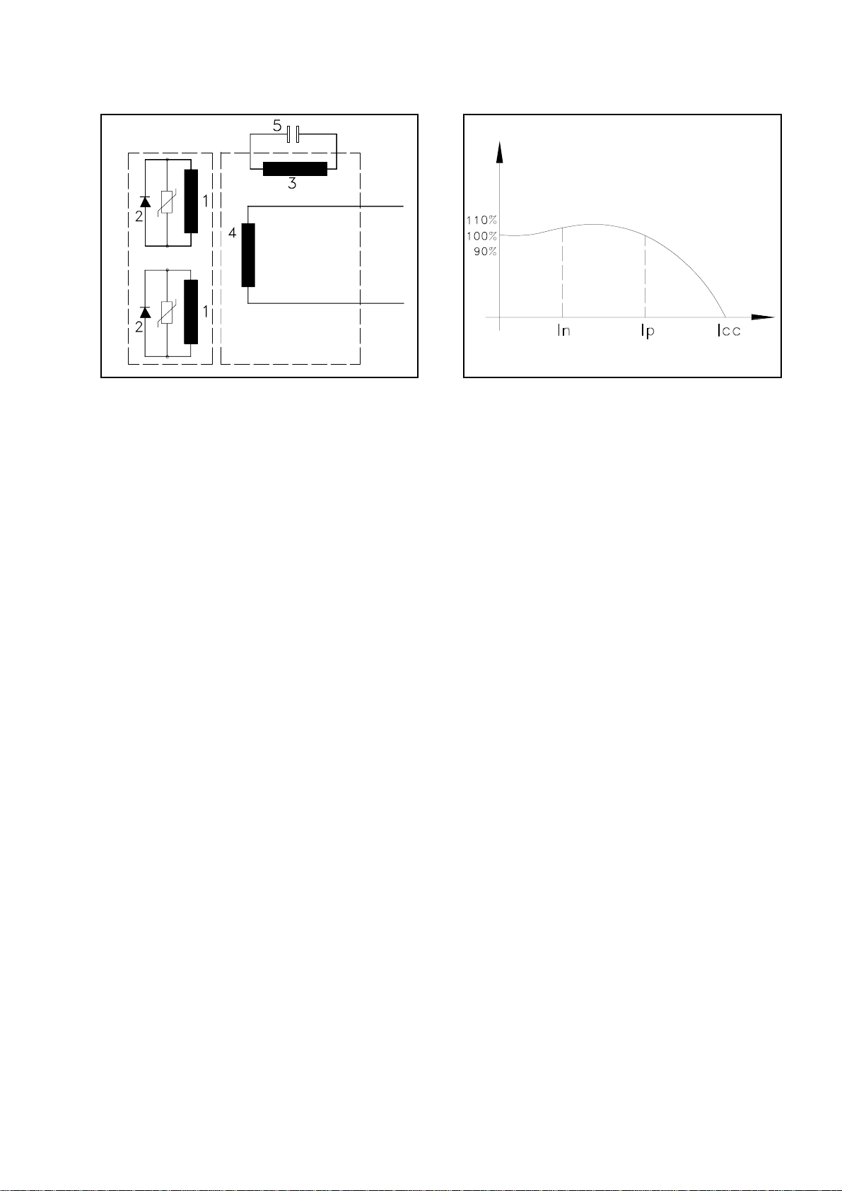
IS 2500 generators are equipped with two pole
synchronousbrushlessalternators.Thesealter-
natorsarealsoself-regulatingandself-exciting
with capacitor (Fig. 1 Ref. 5) connected to the
auxiliary winding of the stator (Fig. 1 Ref. 3).
The alternators generate an alternating voltage
attheterminalsofthemainwinding(Fig.1Ref.
4)havingafrequencyof50or60Hz.(Depend-
ingon whetherthe engineruns at3000 or3600
R.P.M.).
Thegenerationofcurrentisinaccordancewith
the principle described here below:
On starting the unit, the magnetic force of the
rotor (residual magnetism of the nucleus) in-
duces a voltage in the auxiliary winding of
excitation (Fig. 1 Ref. 3). This voltage is fed to
the capacitor (Fig. 1 Ref. 5) which creates a
capacitive current circulating in the closed cir-
cuit constituted of the capacitor and the auxil-
iarywinding.
Thiscapacitivecurrent,createsamagneticfield
reinforcing the magnetism of the rotor, thus
creating in it a voltage which rectified by the
diodes (Fig. 1 Ref. 2) makes a D.C. current
circulate in the induction windings (Fig. 1 Ref.
1).Asaresultofwhicharotatingmagneticfield
is created which generates the rated output in
theprincipal winding (Fig.1Ref. 4)andwhich
can be tapped at the terminals.
The voltage and current values (denoted in
percentagetermsofratedvaluesareasshownin
the diagram (Fig. 2).
As you will note, it is possible to get energy up
to the nominal value. With voltage practically
constant (+/- 5%). Moreover, the alternator at
a voltage not inferior to 70-75% of the rated
voltage,isabletofurnish,asinitialpowerrush,
up to 3 times the rated amperage.
As we know, this initial rush, typical of this
alternator is extremely important to start asyn-
chronous motors.
I generatori della serie IS 2500 sono dotati di
alternatorisenza spazzole,sincroni, adue poli,
autoregolati, autoeccitati, con condensatore
(Fig. 1 Rif. 5) collegato con l'avvolgimento
ausiliario di statore (Fig. 1 Rif. 3). Gli alterna-
torigeneranounatensionealternata,disponibi-
leaimorsettidell'avvolgimentoprincipale(Fig.
1 Rif. 4) a una frequenza di 50/60 Hz. (Corri-
spondenti ad una velocità del motore primo di
3000/3600 giri) secondo il principio di seguito
descritto.
All'avviamento il magnetismo di rotore (ma-
gnetismoresiduodelnucleo)inducenell'avvol-
gimentoausiliario di eccitazione(Fig.1 Rif.3)
una tensione.
Questa tensione è applicata al condensatore
(Fig.1 Rif. 5)e facircolare nelcircuito chiuso,
costituitodalcondensatoreedall'avvolgimento
ausiliario, una corrente capacitiva.
Questa corrente produce un campo magnetico
cherafforzailmagnetismodirotore,generando
in esso una tensione che, raddrizzata dai diodi,
(Fig.1Rif.2)facircolareunacorrentecontinua
negli avvolgimenti induttori (Fig. 1 Rif. 1).
Ilcampomagneticorotantedovutoallacircola-
zione di questa corrente genera a sua volta
nell'avvolgimento principale (Fig. 1 Rif. 4) la
tensione nominale ai morsetti del generatore.
I valori (intesi come percentuale dei valori
nominali) di tensione e corrente disponibili ai
morsetti hanno l'andamento riportato nel dia-
gramma(Fig.2).Comesipuònotareèpossibile
prelevare corrente fino al valore nominale a
tensione praticamente costante (+/- 5%). Ed
inoltre l'alternatore, ad una tensione non infe-
rioreal70-75%delvalorenominale,èancorain
grado di fornire una corrente di picco pari a
circa 3 volte il valore nominale.
Questacaratteristica,tipicadiquestoalternato-
re è particolarmente utile nella fase di avvia-
mento dei motori elettrici asincroni.
3) PRINCIPLE OF POWER3) PRINCIPLE OF POWER
3) PRINCIPLE OF POWER
GENERATIONGENERATION
GENERATION
1) PRINCIPIO DI FUNZIONAMENTO1) PRINCIPIO DI FUNZIONAMENTO
1) PRINCIPIO DI FUNZIONAMENTO

10
IS 2500IS 2500
IS 2500IS 2500
IS 2500 50 Hz50 Hz
50 Hz50 Hz
50 Hz 4.30 Ohm4.30 Ohm
4.30 Ohm4.30 Ohm
4.30 Ohm
60 Hz60 Hz
60 Hz60 Hz
60 Hz 3.80 Ohm3.80 Ohm
3.80 Ohm3.80 Ohm
3.80 Ohm
IS 3500/1IS 3500/1
IS 3500/1IS 3500/1
IS 3500/1 50 Hz50 Hz
50 Hz50 Hz
50 Hz 2.37 Ohm2.37 Ohm
2.37 Ohm2.37 Ohm
2.37 Ohm
60 Hz60 Hz
60 Hz60 Hz
60 Hz 1.86 Ohm1.86 Ohm
1.86 Ohm1.86 Ohm
1.86 Ohm
IS 4500/1IS 4500/1
IS 4500/1IS 4500/1
IS 4500/1 50 Hz50 Hz
50 Hz50 Hz
50 Hz 1.06 Ohm1.06 Ohm
1.06 Ohm1.06 Ohm
1.06 Ohm
IS 5500/1IS 5500/1
IS 5500/1IS 5500/1
IS 5500/1 60 Hz60 Hz
60 Hz60 Hz
60 Hz 0.75 Ohm0.75 Ohm
0.75 Ohm0.75 Ohm
0.75 Ohm
4) SERVICE4) SERVICE
4) SERVICE
All the resistances must be measured when the
alternatoriscold,ambienttemperaturebetween
10 - 30 °C and with an instrument that allows
reading of given values.
The tolerance against the reported values is
around ± 10%.
Readings taken with simpler instruments can
onlyindicate thecontinuity of thewinding but
cannot indicate the presence of short circuits.
N.B.
Apart from the possibilities
suggested here-by, one or more
windings could also be grounded
causing a failure.
We suggest therefore to check by
means of a tester that there is no
continuity between the extremities
of the windings and ground.
4.1)Excitationwinding4.1)Excitationwinding
4.1)Excitationwinding
4) CONTROLLI4) CONTROLLI
4) CONTROLLI
Tutte le misure di resistenza si intendono ese-
guite ad alternatore freddo, temperatura am-
biente 10 - 30 °C e con strumentazione tale da
permettere la lettura dei valori indicati.
Latolleranzarispettoaivaloririportatièindica-
tivamente ± 10%.
letture approssimative, eseguite con strumenti
di portata non adeguata, possono unicamente
indicarelacontinuitàdell'avvolgimentomanon
danno indicazioni su eventuali corto circuiti.
N.B.
Oltre alle possibilità di guasto che
sono indicate in seguito si può
presentare il caso di uno o più
avvolgimentia massa.Si consiglia
quindi di controllare questa
eventualità verificando con un
tester che non ci sia continuità fra
le estremità dei vari avvolgimenti
(identificati nei paragrafi
successivi) e massa.
4.1)Avvolgimento di eccitazione4.1)Avvolgimento di eccitazione
4.1)Avvolgimento di eccitazione
Caratteristiche-Characteristics:Caratteristiche-Characteristics:
Caratteristiche-Characteristics:
Fig. 3Fig. 3
Fig. 3Fig. 3
Fig. 3
Testing method:Testing method:
Testing method:
-Disconnect from the capacitor the two wires
(color: BLUE) coming from the stator (Fig. 3).
-Verifythattheresistancevaluesbetweenthese
two wire terminals are within the limits as
reported in the table above.
REMEDY:REMEDY:
REMEDY:REMEDY:
REMEDY: Replace the stator.
Metodo di controlloMetodo di controllo
Metodo di controllo
-Scollegaredalcondensatoreiduecavi(BLU)
provenienti dallo statore (Fig. 3).
-Verificarechelaresistenzafraleestremitàdei
due cavi rientri nei valori indicati in tabella.
RIMEDIO:RIMEDIO:
RIMEDIO:RIMEDIO:
RIMEDIO: Sostituire lo statore.

11
4.2) Power winding4.2) Power winding
4.2) Power winding
4.3)Avvolgimentodicaricabatteria4.3)Avvolgimentodicaricabatteria
4.3)Avvolgimentodicaricabatteria
Caratteristiche-Characteristic:Caratteristiche-Characteristic:
Caratteristiche-Characteristic:
4.3)Batterychargerwinding (stator)4.3)Batterychargerwinding (stator)
4.3)Batterychargerwinding (stator)
Metodo di controllo:Metodo di controllo:
Metodo di controllo:
-Scollegare dalla morsettiera i cavi di potenza
contrassegnati dalle lettere P1F1P2F2(Fig. 4).
-Verificare che la resistenza fra le estremità di
entrambelecoppiedicaviP1F1e P2F2rientrinei
valoriindicatiintabella.
N.B.N.B.
N.B.N.B.
N.B.Laresistenzatotaledell'avvolgimento(nel
collegamento 220 V o 240 V) si misura
ponticellando F1e P2. La misura effettuata fra i
puntiP1eF2saràildoppiodelvaloreindicatoin
tabella.
RIMEDIO:RIMEDIO:
RIMEDIO:RIMEDIO:
RIMEDIO: Sostituire lo statore
Testing method:Testing method:
Testing method:
-Disconnectfromtheterminalboard,thewires
comingfromthestator,markedbytheletters P1
F1P2F2(Fig. 4).
- Verify that the resistance values between the
two pairs of wire terminals P1F1and P2F2 are
within the limits as reported in the table above.
N.B.N.B.
N.B.N.B.
N.B.Thetotalresistancevalueforpowerwind-
ing (220 V 240 V) is measured connecting F1
and P2. the resistance value measured between
P1andF2is double of that indicated in the table
above.
REMEDY:REMEDY:
REMEDY:REMEDY:
REMEDY: Replace the stator.
Fig. 4Fig. 4
Fig. 4Fig. 4
Fig. 4
IS 2500IS 2500
IS 2500IS 2500
IS 2500 50 Hz50 Hz
50 Hz50 Hz
50 Hz 0.15 Ohm 13 V0.15 Ohm 13 V
0.15 Ohm 13 V0.15 Ohm 13 V
0.15 Ohm 13 V
60 Hz60 Hz
60 Hz60 Hz
60 Hz 0.10 Ohm0.10 Ohm
0.10 Ohm0.10 Ohm
0.10 Ohm 13 V13 V
13 V13 V
13 V
IS 3500/1IS 3500/1
IS 3500/1IS 3500/1
IS 3500/1 50 Hz50 Hz
50 Hz50 Hz
50 Hz 0.18 Ohm0.18 Ohm
0.18 Ohm0.18 Ohm
0.18 Ohm 13 V13 V
13 V13 V
13 V
60 Hz60 Hz
60 Hz60 Hz
60 Hz 0.10 Ohm0.10 Ohm
0.10 Ohm0.10 Ohm
0.10 Ohm 13 V13 V
13 V13 V
13 V
IS 4500/1IS 4500/1
IS 4500/1IS 4500/1
IS 4500/1 50 Hz50 Hz
50 Hz50 Hz
50 Hz 0.10 Ohm0.10 Ohm
0.10 Ohm0.10 Ohm
0.10 Ohm 13 V13 V
13 V13 V
13 V
IS 5500/1IS 5500/1
IS 5500/1IS 5500/1
IS 5500/1 60 Hz60 Hz
60 Hz60 Hz
60 Hz 0.10 Ohm0.10 Ohm
0.10 Ohm0.10 Ohm
0.10 Ohm 13 V13 V
13 V13 V
13 V Fig. 5Fig. 5
Fig. 5Fig. 5
Fig. 5
Testing method:Testing method:
Testing method:
Disconnectthewirescomingfromtheregulator
(Fig. 5) and verify that the resistance values
between the green wires are within the limits
indicated in the table above.
AS AN ALTERNATIVE:
-Verify that the voltage between the GREEN
wires is as reported above.
Metodo di controllo:Metodo di controllo:
Metodo di controllo:
-Scollegare i cavi dal regolatore (Fig. 5) e
verificarechelaresistenzafraicaviverdirientri
neivaloriindicatiintabella.
IN ALTERNATIVA:
-Verificarechefraicaviverdilatensionealter-
natarientri nei valoriindicati intabella.
IS 2500IS 2500
IS 2500IS 2500
IS 2500 50 Hz50 Hz
50 Hz50 Hz
50 Hz 1.00 Ohm1.00 Ohm
1.00 Ohm1.00 Ohm
1.00 Ohm
60 Hz60 Hz
60 Hz60 Hz
60 Hz 0.90 Ohm0.90 Ohm
0.90 Ohm0.90 Ohm
0.90 Ohm
IS 3500/1IS 3500/1
IS 3500/1IS 3500/1
IS 3500/1 50 Hz50 Hz
50 Hz50 Hz
50 Hz 0.52 Ohm0.52 Ohm
0.52 Ohm0.52 Ohm
0.52 Ohm
60 Hz60 Hz
60 Hz60 Hz
60 Hz 0.44 Ohm0.44 Ohm
0.44 Ohm0.44 Ohm
0.44 Ohm
IS 4500/1IS 4500/1
IS 4500/1IS 4500/1
IS 4500/1 50 Hz50 Hz
50 Hz50 Hz
50 Hz 0.20 Ohm0.20 Ohm
0.20 Ohm0.20 Ohm
0.20 Ohm
IS 5500/1IS 5500/1
IS 5500/1IS 5500/1
IS 5500/1 60 Hz60 Hz
60 Hz60 Hz
60 Hz 0.18 Ohm0.18 Ohm
0.18 Ohm0.18 Ohm
0.18 Ohm
4.2)Avvolgimento di potenza4.2)Avvolgimento di potenza
4.2)Avvolgimento di potenza
Caratteristiche-Characteristic:Caratteristiche-Characteristic:
Caratteristiche-Characteristic:

12
N.B.:N.B.:
N.B.:N.B.:
N.B.: Eseguire questa misura senza carichi
applicati al generatore, con batteria d'avvia-
mentoinseritaedopoaverattesoqualcheminu-
todall'avviamento.
RIMEDIO:RIMEDIO:
RIMEDIO:RIMEDIO:
RIMEDIO: Sostituire lo statore.
IMPORTANTEIMPORTANTE
IMPORTANTE
Il circuito del carica batteria è
dotatodiun regolatoreelettronico
di carica in grado di erogare max.
15 A a 12 V; in caso di anomalia
nella ricarica della batteria dopo
aver controllato la resistenza
dell'avvolgimento ed il fusibile, di
consigliadisostituireilregolatore.
N.B.:N.B.:
N.B.:N.B.:
N.B.: The above measurements must be done
afterfewminutesfromthestarting,withoutany
load applied to the generator and with the
starting battery connected.
REMEDY:REMEDY:
REMEDY:REMEDY:
REMEDY: Replace the stator.
WARNINGWARNING
WARNINGWARNING
WARNING
The battery charger circuit,
equippedwithanelectroniccharger
regulator, has a max. output of 15
A at 12 V. If the defect on the
battery charger circuit results not
to depend on the fuse or on the
stator windings, it's advisable to
replace the regulator
4.4)Fusibilecaricabatteria4.4)Fusibilecaricabatteria
4.4)Fusibilecaricabatteria
Caratteristiche-Characteristics:Caratteristiche-Characteristics:
Caratteristiche-Characteristics:
4.4) Battery charger fuse4.4) Battery charger fuse
4.4) Battery charger fuse
Fig. 6Fig. 6
Fig. 6Fig. 6
Fig. 6
Metodo di controllo:Metodo di controllo:
Metodo di controllo:
-Verificarelacontinuitàalleestremitàdelfusi-
bile (Fig. 6 Rif.1).
RIMEIDO:RIMEIDO:
RIMEIDO:RIMEIDO:
RIMEIDO:Sostituireil fusibile.
Testing method:Testing method:
Testing method:
-Verify the continuity at its terminals (Fig. 6
Ref.1).
REMEDY:REMEDY:
REMEDY:REMEDY:
REMEDY: Replace the fuse.
4.5)Interruttoretermico(statore)4.5)Interruttoretermico(statore)
4.5)Interruttoretermico(statore)
Caratteristiche:Caratteristiche:
Caratteristiche:
Normalmentechiuso.Temperaturad'interven-
to 160 °C.
4.5)Thermal switch(stator)4.5)Thermal switch(stator)
4.5)Thermal switch(stator)
Characteristics:Characteristics:
Characteristics:
Normallyclosed.Tripsatatemperatureof160°C
Fig. 7Fig. 7
Fig. 7Fig. 7
Fig. 7
IS 2500IS 2500
IS 2500IS 2500
IS 2500 50 Hz50 Hz
50 Hz50 Hz
50 Hz 20 Amp20 Amp
20 Amp20 Amp
20 Amp
60 Hz60 Hz
60 Hz60 Hz
60 Hz 20 Amp20 Amp
20 Amp20 Amp
20 Amp
IS 3500/1IS 3500/1
IS 3500/1IS 3500/1
IS 3500/1 50 Hz50 Hz
50 Hz50 Hz
50 Hz 30 Amp30 Amp
30 Amp30 Amp
30 Amp
60 Hz60 Hz
60 Hz60 Hz
60 Hz 30 Amp30 Amp
30 Amp30 Amp
30 Amp
IS 4500/1IS 4500/1
IS 4500/1IS 4500/1
IS 4500/1 50 Hz50 Hz
50 Hz50 Hz
50 Hz 30 Amp30 Amp
30 Amp30 Amp
30 Amp
IS 5500/1IS 5500/1
IS 5500/1IS 5500/1
IS 5500/1 60 Hz60 Hz
60 Hz60 Hz
60 Hz 30 Amp30 Amp
30 Amp30 Amp
30 Amp

13
Metodo di controllo:Metodo di controllo:
Metodo di controllo:
-Scollegaredallamorsettieraiduecavi(NERI)
provenienti dallo statore ai morsetti N. 17 e N.
18 (Fig. 7).
-Verificarelacontinuitàfraledueestremitàdei
cavi.
RIMEDIO:RIMEDIO:
RIMEDIO:RIMEDIO:
RIMEDIO: Sostituire lo statore
N.B.:N.B.:
N.B.:N.B.:
N.B.:L'interruttoretermicopuòintervenireper
sovraccarico o per sovratemperatura.
Verificare quindi, se è necessario, i carichi ap-
plicatielatemperaturad'eserciziodelgenerato-
re, con particolare attenzione alla sua installa-
zione.
Testing method:Testing method:
Testing method:
-Disconnect from the terminal board, the two
wires(colour:Black),connectingterminalsNo.
17 and 18 (Fig. 7) to the stator.
-Checkthatthereiscontinuitybetweenthetwo
ends of the two wires.
REMEDY:REMEDY:
REMEDY:REMEDY:
REMEDY: Replace the stator.
N.B.:N.B.:
N.B.:N.B.:
N.B.: The thermal switch can trip because of
overload or overheat. It's hence important to
verify the loads connected and the running
temperature of the generator with an eye on
installation to verify if it may have contributed
to the problem.
4.6) Avvolgimento di rotore (n°2)4.6) Avvolgimento di rotore (n°2)
4.6) Avvolgimento di rotore (n°2)
Caratteristiche-Caracteristics:Caratteristiche-Caracteristics:
Caratteristiche-Caracteristics:
4.6) Rotor winding (no. 2)4.6) Rotor winding (no. 2)
4.6) Rotor winding (no. 2)
Fig. 8Fig. 8
Fig. 8Fig. 8
Fig. 8
IS 2500IS 2500
IS 2500IS 2500
IS 2500 50 Hz50 Hz
50 Hz50 Hz
50 Hz 0.50 Ohm0.50 Ohm
0.50 Ohm0.50 Ohm
0.50 Ohm
60 Hz60 Hz
60 Hz60 Hz
60 Hz 0.50 Ohm0.50 Ohm
0.50 Ohm0.50 Ohm
0.50 Ohm
IS 3500/1IS 3500/1
IS 3500/1IS 3500/1
IS 3500/1 50 Hz50 Hz
50 Hz50 Hz
50 Hz 0.57 Ohm0.57 Ohm
0.57 Ohm0.57 Ohm
0.57 Ohm
60 Hz60 Hz
60 Hz60 Hz
60 Hz 0.57 Ohm0.57 Ohm
0.57 Ohm0.57 Ohm
0.57 Ohm
IS 4500/1IS 4500/1
IS 4500/1IS 4500/1
IS 4500/1 50 Hz50 Hz
50 Hz50 Hz
50 Hz 0.74 Ohm0.74 Ohm
0.74 Ohm0.74 Ohm
0.74 Ohm
IS 5500/1IS 5500/1
IS 5500/1IS 5500/1
IS 5500/1 60 Hz60 Hz
60 Hz60 Hz
60 Hz 0.74 Ohm0.74 Ohm
0.74 Ohm0.74 Ohm
0.74 Ohm
Testing method:Testing method:
Testing method:
-Disconnect the wires of the rotor winding.
-Verify that the resistance value between the
wire terminals is as reported in the table above
(Fig. 8).
REMEDY:REMEDY:
REMEDY:REMEDY:
REMEDY: Replace the rotor.
WARNINGWARNING
WARNINGWARNING
WARNING
If there is still no power it could
depend very rarely on the
dissipation of the residual
magnetism of the rotor.
So as to solve the problem it is
advisabletoconnecta12Vbattery
tothe capacitorterminals or tothe
powerterminals,forafewinstants,
whilethegeneratorisrunning.The
rotor will get magnetized
immediately.
Metodo di controllo:Metodo di controllo:
Metodo di controllo:
-Scollegare le estremità dell'avvolgimento di
rotore.
-Verificarechelaresistenzafraledueestremità
rientri nei valori indicati. (Fig. 8).
RIMEDIO:RIMEDIO:
RIMEDIO:RIMEDIO:
RIMEDIO: Sostituire lo statore
IMPORTANTEIMPORTANTE
IMPORTANTE
La mancanza di tensione in uscita
può essere causata
eccezionalmentedallamancanzao
insufficienza di magnetismo
residuo del rotore.
Comeprimointerventosiconsiglia,
con il generatore in moto, di
collegareperunattimounabatteria
12V ai terminalidel condensatore
o, all'uscita di potenza.
In questo modo il rotore viene
istantaneamente magnetizzato.

14
4.7)Diodidirotore4.7)Diodidirotore
4.7)Diodidirotore
Caratteristiche :Caratteristiche :
Caratteristiche :21 A 800 V
Direzione normaleDirezione normale
Direzione normale 0.66 Ohm0.66 Ohm
0.66 Ohm0.66 Ohm
0.66 Ohm
Direzione inversaDirezione inversa
Direzione inversa Mancanza di cont.Mancanza di cont.
Mancanza di cont.Mancanza di cont.
Mancanza di cont. Normal directionNormal direction
Normal directionNormal direction
Normal direction 0.66 Ohm0.66 Ohm
0.66 Ohm0.66 Ohm
0.66 Ohm
Reverse directionReverse direction
Reverse direction No continuity.No continuity.
No continuity.No continuity.
No continuity.
4.7) Rotor diodes4.7) Rotor diodes
4.7) Rotor diodes
Caracteristics:Caracteristics:
Caracteristics: 21 A 800 V
Metodo di controllo:Metodo di controllo:
Metodo di controllo:
-Scollegare il cavo dal diodo.
-Verificare che la resistenza fra (+) e massa
rientri nei valori indicati. (Fig. 9).
-Verificare che invertendo i puntali del tester
non ci sia continuità.
RIMEDIO:RIMEDIO:
RIMEDIO:RIMEDIO:
RIMEDIO: Sostituire il diodo.
N.B.:N.B.:
N.B.:N.B.:
N.B.: In caso di diodo difettoso è necessario
sostituireancheilvaristore(Fig.9Rif.1)anche
se apparentemente integro.
Testing method:Testing method:
Testing method:
-Disconnect the wire from the diode.
-Verify that the resistance value between (+)
and ground is as reported in the table above.
(Fig. 9).
-Invertthetesterterminalsandverifythatthere
is no continuity in the reverse direction.
REMEDY:REMEDY:
REMEDY:REMEDY:
REMEDY: Replace the diode.
N.B.:N.B.:
N.B.:N.B.:
N.B.: If the diode is defective it is necessary to
replace the varistor too, (Fig. 9 Ref. 1), even if
it appears intact.
Fig. 9Fig. 9
Fig. 9Fig. 9
Fig. 9
Metodo di controllo:Metodo di controllo:
Metodo di controllo:
-Scollegare i cavi (BLU) dal condensatore.
-Posizionare il tester sul valore più alto della
scalaohmica(x1000),lalancettadovràoscilla-
revelocementeavantieindietronelmomentoin
cui i puntali del tester toccheranno i terminali
del condensatore (Fig. 10).
Testing method:Testing method:
Testing method:
-Disconnect the wires (colour: BLUE) of the
capacitor.
-With the tester set to (x1000) connect it with
thecapacitorterminals.Theneedlemustswing
sharply away an back the moment the tester
prods touch the capacitor terminals (Fig. 10).
Fig. 10Fig. 10
Fig. 10Fig. 10
Fig. 10
4.8) Condensatore4.8) Condensatore
4.8) Condensatore
Caratteristiche-Characteristics:Caratteristiche-Characteristics:
Caratteristiche-Characteristics:
IS 2500IS 2500
IS 2500IS 2500
IS 2500 12.5 microfarad12.5 microfarad
12.5 microfarad12.5 microfarad
12.5 microfarad 500 V500 V
500 V500 V
500 V
IS 3500/1IS 3500/1
IS 3500/1IS 3500/1
IS 3500/1 20 microfarad20 microfarad
20 microfarad20 microfarad
20 microfarad 500 V500 V
500 V500 V
500 V
IS 4500/1IS 4500/1
IS 4500/1IS 4500/1
IS 4500/1 35 microfarad35 microfarad
35 microfarad35 microfarad
35 microfarad 500 V500 V
500 V500 V
500 V
IS 5500/1IS 5500/1
IS 5500/1IS 5500/1
IS 5500/1 35 microfarad35 microfarad
35 microfarad35 microfarad
35 microfarad 500 V500 V
500 V500 V
500 V
4.8)Capacitor4.8)Capacitor
4.8)Capacitor

15
N.B.:N.B.:
N.B.:N.B.:
N.B.: Con questa prova si verifica che il con-
densatore non sia in cortocircuito o interrotto.
Unadiminuzionedicapacità,chehacomeeffet-
to una diminuzione della tensione a vuoto, è
difficilmentevalutabile.
Inquestocaso,verificatelealtrepossibilicause,
si consiglia di sostituire il condensatore.
RIMEDIO:RIMEDIO:
RIMEDIO:RIMEDIO:
RIMEDIO: Sostituire il condensatore
N.B.:N.B.:
N.B.:N.B.:
N.B.:Withthistest,thecapacitorischeckedfor
short circuits/interruptions. If however the ca-
pacityisdiminished,resultinginavoltagedrop
under no load condition, this test cannot diag-
nose the problem. In this case we suggest that
the capacitor be replaced after having checked
for other possible faults.
REMEDY:REMEDY:
REMEDY:REMEDY:
REMEDY: Replace the capacitor.
4.9) Scheda relè4.9) Scheda relè
4.9) Scheda relè 4.9) Relay p.c. board4.9) Relay p.c. board
4.9) Relay p.c. board4.9) Relay p.c. board
4.9) Relay p.c. board
Fig. 11Fig. 11
Fig. 11Fig. 11
Fig. 11
1) Fusibile 1 A / Fuse 1 A1) Fusibile 1 A / Fuse 1 A
1) Fusibile 1 A / Fuse 1 A
2) Relè elettrovalvola e pompa nafta /2) Relè elettrovalvola e pompa nafta /
2) Relè elettrovalvola e pompa nafta /
Fuel solenoid and fuel pump relay Fuel solenoid and fuel pump relay
Fuel solenoid and fuel pump relay
3) Relè avviamento / Start relay3) Relè avviamento / Start relay
3) Relè avviamento / Start relay
4) Diodi / Diodes4) Diodi / Diodes
4) Diodi / Diodes
4.9.1)Fusibile4.9.1)Fusibile
4.9.1)Fusibile
Caratteristiche:Caratteristiche:
Caratteristiche:1A4.9.1) Fuse4.9.1) Fuse
4.9.1) Fuse4.9.1) Fuse
4.9.1) Fuse
Caracteristics:Caracteristics:
Caracteristics:1A
Metodo di controllo:Metodo di controllo:
Metodo di controllo:
-Verificarelacontinuitàalleestremitàdelfusi-
bile (Fig. 12 Rif.1).
RIMEDIO:RIMEDIO:
RIMEDIO:RIMEDIO:
RIMEDIO:Sostituireilfusibile
Testing method:Testing method:
Testing method:
-Verify the continuity at its terminals (Fig. 12
Ref.1).
REMEDY:REMEDY:
REMEDY:REMEDY:
REMEDY: Replace the fuse
Fig. 12Fig. 12
Fig. 12Fig. 12
Fig. 12

16
4.9.2)Relè4.9.2)Relè
4.9.2)Relè
Caratteristiche-Characteristic:12VCaratteristiche-Characteristic:12V
Caratteristiche-Characteristic:12V
30A30A
30A30A
30A
Testing method:Testing method:
Testing method:
-Remove the relay.
-Verify that there is continuity between 85 and
86 (Fig. 13).
-Verify that exciting the coil (apply 12 V to
terminals85and86)makesterminals30and87
CLOSE and terminal 30 and 87b OPEN.
REMEDY:REMEDY:
REMEDY:REMEDY:
REMEDY: Replace the relay.
Metodo di controllo:Metodo di controllo:
Metodo di controllo:
-Disinserireilrelè.
-Verificarechefraipunti85-86visiacontinuità
(Fig. 13).
-Verificare che eccitando la bobina (12 v ai
morsetti 85 - 86), il contatto 30 - 87 CHIUDE,
mentre il contatto 30 - 87b APRE.
RIMEDIO:RIMEDIO:
RIMEDIO:RIMEDIO:
RIMEDIO: Sostituire il relè
Fig. 13Fig. 13
Fig. 13Fig. 13
Fig. 13
30 - 87 Contatto normalmente APERTO30 - 87 Contatto normalmente APERTO
30 - 87 Contatto normalmente APERTO
30 - 87 Contact normally OPEN30 - 87 Contact normally OPEN
30 - 87 Contact normally OPEN
30-87bContattonormalmenteCHIUSO30-87bContattonormalmenteCHIUSO
30-87bContattonormalmenteCHIUSO
30 - 87b Contact normally CLOSED30 - 87b Contact normally CLOSED
30 - 87b Contact normally CLOSED
4.9.3)Diodi4.9.3)Diodi
4.9.3)Diodi
Caratteristiche: 1 A 1000 VCaratteristiche: 1 A 1000 V
Caratteristiche: 1 A 1000 V
Direzione normaleDirezione normale
Direzione normale 0.850 Ohm0.850 Ohm
0.850 Ohm0.850 Ohm
0.850 Ohm
Direzione inversaDirezione inversa
Direzione inversa Mancanza di cont.Mancanza di cont.
Mancanza di cont.Mancanza di cont.
Mancanza di cont. Normal directionNormal direction
Normal directionNormal direction
Normal direction 0.850 Ohm0.850 Ohm
0.850 Ohm0.850 Ohm
0.850 Ohm
Reverse directionReverse direction
Reverse direction No continuityNo continuity
No continuityNo continuity
No continuity
4.9.3) Diodes4.9.3) Diodes
4.9.3) Diodes
Caracteristics: 1 A 1000 VCaracteristics: 1 A 1000 V
Caracteristics: 1 A 1000 V
Fig. 14Fig. 14
Fig. 14Fig. 14
Fig. 14
Testing method:Testing method:
Testing method:
-Remove the relays
-Disconnectthewires from theterminalboard.
-Verify that the resistance value between the
diode's terminal is as reported above.
-Invert the tester prods and verify that there is
no continuity in.
REMEDY:REMEDY:
REMEDY:REMEDY:
REMEDY: Replace the diode.
Metodo di controllo:Metodo di controllo:
Metodo di controllo:
-Smontare i relè.
-Scollegare i cavi dalla morsettiera (Fig. 14).
-Verificarechelaresistenzafraledueestremità
rientrineivaloriindicati.
-Verificare che invertendo i puntali del tester
non ci sia più continuità.
RIMEDIO:RIMEDIO:
RIMEDIO:RIMEDIO:
RIMEDIO: Sostituire il diodo
4.9.2)Relay4.9.2)Relay
4.9.2)Relay

17
4.9.3)Diodi4.9.3)Diodi
4.9.3)Diodi
Caratteristiche: 6A 600V
Metodo di controllo:Metodo di controllo:
Metodo di controllo:
-Verificarechelaresistenzafraledueestremita'
rientrineivaloriindicati(Fig.15)
-Verificare che invertendo i puntali del
tester non ci sia piu' continuita'.
RIMEDIO:RIMEDIO:
RIMEDIO:RIMEDIO:
RIMEDIO: Sostituire il diodo
Fig.15Fig.15
Fig.15Fig.15
Fig.15
DirezioneDirezione
DirezioneDirezione
Direzione normalenormale
normalenormale
normale 0.75 Ohm0.75 Ohm
0.75 Ohm0.75 Ohm
0.75 Ohm
DirezioneDirezione
DirezioneDirezione
Direzione inversa Mancanza di cont.inversa Mancanza di cont.
inversa Mancanza di cont.inversa Mancanza di cont.
inversa Mancanza di cont.
4.9.3)Diodes4.9.3)Diodes
4.9.3)Diodes
Characteristics: 6A 600V
Testing method:Testing method:
Testing method:
-Verify that the resistance value between it's
terminals is as reported above(Fig.15)
-Invertthetesterterminalsandverifythatthere
is no continuity in the reverse
REMEDY:REMEDY:
REMEDY:REMEDY:
REMEDY:Replace the diode
Normal directionNormal direction
Normal direction 0.75 Ohm0.75 Ohm
0.75 Ohm0.75 Ohm
0.75 Ohm
Reverse directionReverse direction
Reverse direction No continuityNo continuity
No continuityNo continuity
No continuity

18
Metodo di controllo:Metodo di controllo:
Metodo di controllo:
-Verificaretuttelefunzionidelgeneratore(av-
viamento, arresto, dispositivi di sicurezza).
-Verificare le possibili cause di mancato
funzionamento(batteria, motorino, avviamen-
to, pressostato, termostato, interruttore termi-
cofusibile, schedarele')
RIMEDIO:RIMEDIO:
RIMEDIO:RIMEDIO:
RIMEDIO: Sostituire il circuito stampato
(Fig.16Rif.1)
Testing method:Testing method:
Testing method:
-Verify all generator's functions (start, stop,
safetydevices).
-Verify all the possible causes of not proper
running (battery,starter, oil pressure switch,
water temperature switch, alternator thermo-
stat, relay board fuse)
REMEDY:REMEDY:
REMEDY:REMEDY:
REMEDY:Replacetheprintedcircuit.(Fig.16
Ref.1)
4.9.5) Circuito stampato4.9.5) Circuito stampato
4.9.5) Circuito stampato 4.9.5)Printed circuit4.9.5)Printed circuit
4.9.5)Printed circuit4.9.5)Printed circuit
4.9.5)Printed circuit
Fig. 16Fig. 16
Fig. 16Fig. 16
Fig. 16
Quando il gruppo si arresta, per l'intervento
di una protezione, sul display del pannello
comandi scompare l'indicazione delle ore di
funzionamento e compare un codice ad indi-
care la causa dell'arresto del gruppo
elettrogeno.
Nella tabella sono riportati tutti i codici e il
loro significato
When the unit stops because of an alarm
intervention, the operating time indication
disappearsfrom thecontrolpanel display and
a code appears to indicate the cause of the
generator stop.
In the table below all the codes and their
meaning are listed.
TABLE OF ALARM CODES
CODE REASON FOR ALARM
E - 80 No power to genset
E - 81 Oil pressure low
E - 82 Motor temperature high
E - 83 Alternator temperature high
E - 85 Generator set overloaded
E - 87 After 30 s. from start-up, the genset
has not reached 80% of rated voltage
batt Battery voltage low
TABELLA CODICI DI ALLARME
CODICE CAUSA INTERVENTO PROTEZIONE
E - 80 Mancanza tensione gruppo
E - 81 Bassa pressione olio
E - 82 Alta temperatura motore
E - 83 Alta temperatura alternatore
E - 85 Sovraccarico gruppo elettrogeno
E - 87 A 30 sec. dall'avvio il gruppo non
raggiunge 80% della tensione nominale
batt Bassa tensione di batteria

19
CodCod
CodCod
Cod. E -80.E - 80
.E - 80.E- 80
.E - 80 Tale codice indica che il gruppo si
è arrestato per mancanza completa di tensione
= 0 V. La comparsa di tale codice sta ad indi-
care:
- che il pannello di comando non è in grado di
leggere la tensione del l'alternatore per l'in-
terruzione di una connessione elettrica;
- che l'alternatore è danneggiato.
CodCod
CodCod
Cod.E-81.E- 81
.E- 81.E- 81
.E- 81 Tale codice indica che il gruppo si
è arrestato per pressione dell'impianto di
lubrificazione del motore è insufficiente.
CodCod
CodCod
Cod. E -82.E - 82
.E - 82. E-82
.E - 82 Tale codice indica che il gruppo si
è arrestato perché il motore ha raggiunto tem-
perature troppo elevate.
CodCod
CodCod
Cod. E -83.E - 83
.E - 83. E-83
.E - 83 Tale codice indica che il gruppo si
è arrestato perché l'alternatore ha raggiunto
temperature troppo elevate.
CodCod
CodCod
Cod.E-85.E- 85
.E- 85.E- 85
.E- 85 Tale codice indica che il gruppo si
è arrestato perché la tensione è scesa sotto il
70 % del valore nominale per un tempo supe-
riore a 15 s.
CodCod
CodCod
Cod.E-87.E- 87
.E- 87.E- 87
.E- 87 Tale codice indica che il gruppo si
è arrestato perché la tensione del gruppo
elettrogeno, dopo 30 s. dall'avviamento non ha
raggiunto80% delvalore nominale.Taleincon-
veniente può essere causato da un numero di
giri del motore insufficiente o un guasto all'al-
ternatore.
CodCod
CodCod
Cod. ba. ba
. ba. ba
. batt.tt.
tt.tt.
tt. Tale codice indica che la tensione
di batteria è insufficiente. La comparsa di que-
sto codice non arresta il gruppo elettrogeno.
Code E-80Code E-80
Code E-80Code E-80
Code E-80 This code indicates that the group
hasstoppedduetoacompletelackofvoltage=
0 V. Display of this code means that:
- the control panel is not able to read the
voltage in the alternator due to a break in an
electrical connection;
- the alternator is damaged.
Code E-81Code E-81
Code E-81Code E-81
Code E-81 This code indicates that the group
has stopped because the pressure in the motor
lubrication system is insufficient.
Code E-82Code E-82
Code E-82Code E-82
Code E-82 This code indicates that the group
has stopped because the motor is too hot.
Code E-83Code E-83
Code E-83Code E-83
Code E-83 This code indicates that the group
has stopped because the alternator is too hot.
Code E-85Code E-85
Code E-85Code E-85
Code E-85 This code indicates that the group
hasstoppedbecausethevoltagehasdroppedto
under 70% of the rated value for over 15
seconds.
Code E-87Code E-87
Code E-87Code E-87
Code E-87This code indicates that the group
has stopped because, 30’ after start-up, the
voltageinthegeneratorgrouphasnotreached
80%of therated voltage. This maybe because
the engine revs are too low or because the
alternator is broken.
Code battCode batt
Code battCode batt
Code batt. This code indicates that the battery
voltage is too low. When this code appears the
generator group is not stopped.

20
4.9.6)Scambiatoredicalore(aria/acqua)4.9.6)Scambiatoredicalore(aria/acqua)
4.9.6)Scambiatoredicalore(aria/acqua)
Caratteristiche:
Libero da incrostazioni
--
--
-Distaccare i tubi acqua(Fig.17 Rif.1/2)
-Togliere le viti (Fig.17 Rif.3) e rimuovere lo
scambiatore.
-Verificarevisivamente
Testing method:Testing method:
Testing method:
REMEDY:REMEDY:
REMEDY:REMEDY:
REMEDY:Washexchangerimmergingit ina
water (90%) and hydrochloric acid (10%)
solution at 50'C temperature.
Replace it if necessary.
4.9.6)Heat exchanger (air / water)4.9.6)Heat exchanger (air / water)
4.9.6)Heat exchanger (air / water)
Characteristics:
Fouling free
-Disconnect thewaterhoses (Fig.12Ref.1/2).
-Removethescrews(fig.17Ref.3)andtheheat
exchanger.
-Verifyvisually.
Fig. 17Fig. 17
Fig. 17Fig. 17
Fig. 17
Metodo di controllo:Metodo di controllo:
Metodo di controllo:
RIMEDIO:RIMEDIO:
RIMEDIO:RIMEDIO:
RIMEDIO:Immergere lo scambiatore in una
soluzionediacqua(90%)eacidocloridico(10%)
alla temperatura di 10 'C.Sostituire se necessa-
rio
This manual suits for next models
6
Table of contents
Other Mase Generators Inverter manuals

Mase Generators
Mase Generators IS 9 User manual

Mase Generators
Mase Generators LX 2000 User manual

Mase Generators
Mase Generators Marine IS 8 User manual

Mase Generators
Mase Generators PD 50 S User manual

Mase Generators
Mase Generators PD 10 S User manual

Mase Generators
Mase Generators SILENT 12 User manual

Mase Generators
Mase Generators MW 180 DS User manual