DRYDEN AQUA DA-GEN User manual

DA-GEN®
Dryden Aqua Generator
1
2
1
2
3
4
5
3
4
1
2
3
4
5
5
6
5
6
1
2 3
4
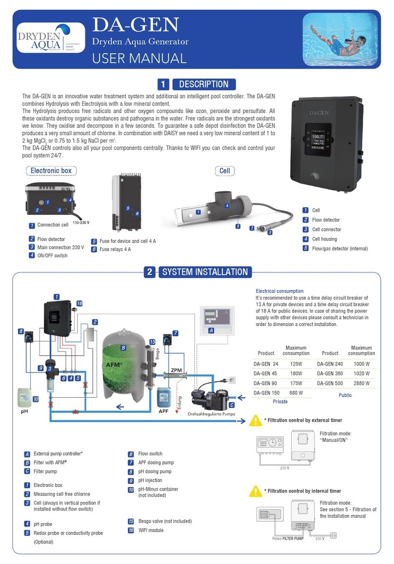
1. DESCRIPTION
Control panel Cell
4 Amp fuse for panel and cell
4 Amp fuse relays
The DA-GEN®is an innovative water treatment system and additional an intelligent pool controller. The DA-GEN®
combines Hydrolysis with Electrolysis with a low mineral content.
The Hydrolysis produces free radicals and other oxygen compounds like ozone, peroxide and persulfate. All these
oxidants destroy organic substances and pathogens in the water. Free radicals are the strongest oxidants we
know. They oxidise and decompose in a few seconds. To guarantee a safe residual disinfection the DA-GEN®
produces a very small amount of chlorine. In combination with Dryden DAISY®we need a very low mineral
content of 1 to 2 kg MgCl2or NaCl per m3.
The DA-GEN®also controls all your pool equipment centrally. Thanks to WiFi you can check and control your
pool system 24/7.
110-230 V
Cell
Gas detector connector
Cell connector
Cell housing
Gas detector (internal)1
Connection cell
Gas detector connection
Main 230V connection
ON/OFF switch
USER MANUAL
2. MAIN SCREEN
PLUS key
Modify value/selection
MINUS key
Modify value/selection
OK key
Select/conrm
UP key
Navigation up
DOWN key
Navigation down
RETURN/ESCAPE
key
Current time
Production intensity
in % (normally 40-100%)
Communication display – mother board
Heating ON/OFF
Manual
Automatic
man
aut
Status of ltration relay
(see chapter 12- Filtration)
Automatic measurements: pH/redoX/
free chlorine/conductivity (according to options)
Lights
Manual / Automatic
man aut
Water temperature
Polarity 1 / Polarity 2
Filtration stopped due to lack of water ow
Waiting time
Cover
Pol 1
Flow
Low
---
Pol 2
If the cover is open the ltration speed is “medium” (if with
frequency controlled pump)
Lack of conductivity or salt / low water temperature / scale on
cell / exhausted cell (check working hours)
7.4
7.0
ON/OFF
pH Setpoint
Setpoint pH minimum (if using pH-Minus and pH-Plus)
Function of pH dosing pump
AL3 Maximum dosing time exceeded ( to reset the alarm)
Flow alarm (Paddle/Gas)
700
FL 1
ON/OFF Additional chlorine pump (optional)
Minimum Redox Setpoint
AL3 Maximum dosing time exceeded ( to reset the alarm)
Flow alarm (Paddle/Gas) / Flow alarm rotameter Cl2
AL3
FL 1
0.30
FL 2
Free Chlorine Minimum Setpoint
Maximum dosing time exceeded ( to reset the alarm)
Status of the auxiliary relays
TANK Low level pH-Minus bottle
12:30 25º
man
off
man
off
Cover
Pol 1
LOW
100 %
hydrolysis
pH 7.4 OFF
AL37.0
7.4
Rx
mV
700 OFF
AL3FL1
700
Cl
ppm
0.30 FL2
FL1
0.30
measures
1 2 3 4
TANK
Shortcut Backwash
(press 3s)
Shortcut Light
(press 3s)
1Except DA-GEN 150
1EN

7
2
A
B
1
3
9
13
15
11
4
56
8
C
12
7
3
A
B
C
1
2
4
5
6
8
9
10
11
12
13
14
10
15
14
3. SYSTEM INSTALLATION
* Filtration control by external timer
Filtration mode:
“Manual/ON”
230 V
* Filtration control by internal timer
Filtration mode:
Automatic
see Chapter 12
230 VLINKS TO FILTER PUMP
Paddle ow switch and temperature module
APF®dosing pump
pH dosing pump
pH injection
Prelter
Wi module (see chapter 15)
APF®
(not included)
pH-Minus
(not included)
If Outdoor pool: ACO®
(not included)
Besgo valve (not included)
External pump controller*
Filter with AFM®
Filter pump
Control Panel
Free chlorine cell with rotameter
Cell
(always in vertical position if installed without paddle
ow switch )
pH probe
Redox probe and/or conductivity probe
Product
Maximum
consumption
DA-GEN 24 90 W
DA-GEN 45 125 W
DA-GEN 90 180 W
DA-GEN 150 175 W
Private
Product
Maximum
consumption
DA-GEN 240 680 W
DA-GEN 360 1000 W
DA-GEN 500 1020 W
DA-GEN 750 2880 W
Public
Electrical consumption
Use of a 13 Amp time delay circuit breaker is recommended
for private devices and a 16 A breaker for public devices.
In case of sharing the power supply with other devices
please consult a technician in order to dimension a correct
installation.
Variable Rate Pump
To Earth
6
1 2 3
1
1
2
2
3
4
5
6
7
8
1 2 3 4
3
3
4
4
1
1
2
2
4. ELECTRICAL CONNECTIONS
Connection ext. display*
Connection WIFI module
Device control SLAVE
Variable speed pump
*IF connecting 2 displays on
the device, remember not to
connect the second display in
this communication channel.
Use the “ext. Display” socket
instead.
Chlorine probe detector
FL2 (rotameter)
Cover 1& 5
Conductivity probe
Paddle Flow switch
2& 5
FL1
Suction lance pH-
Minus TANK 4& 5
Temperature probe pHredoX
Free chlorine
pH
pH dosing pump
1& 2
AUX 4
Heating control
13 & 14
AUX 3
ACO®
11 & 12
LIGHT
Lighting control
9& 10
AUX 2
Besgo backwash
valve
5& 6
FILTER PUMP
Filtration control
14
12 11
A1 A2
LN
AUX 1
Dosing pump occulation
APF® 3& 4
3black
5brown
6blue
1red
2yellow
3black
1yellow
2transparent
1slow 2medium
3fast 4common
1red 2yellow
3green 4black
3red 4black
1brown 2blue
7& 8
CONNECT ALL THE SENSORS CAREFULLY, A
BAD CONNECTION MAY CAUSE IRREPARABLE
DAMAGE TO THE DEVICE
123
1
2
3
1234567 8 9 10 11 12 13 14
DRY CONTACT110-230 V max. 3.15 A
2EN

1
2
3
Adjust the alkalinity between 100 and 200
ppm.
Adjust the pH to 7.4.
Adjust the chlorine between 0.1 and 0.5
ppm.
5. INITIAL WATER ADJUSTMENTS
1
2
We recommend to add 1 to 2 kg magnesium chloride (MgCl2) or normal salt (NaCl)
per m3of water. The TDS should be at around 1200. It is recommended to mix them,
for example in a ratio of 1:1 to 1:3 (MgCl2:NaCl).
Add the magnesium chloride or salt directly to your swimming pool and let the
system run.
In outdoor pools it is necessary to use ACO®.
Water adjustments Adding activator/salt to the water
Attention: Let the system run 24 hours before
calibrating and make sure to have a free
chlorine level of at least 0.3 ppm free chlorine!
6. SYSTEM SETTINGS
6.8 6.96.6 6.7
6.1 6.3 6.46.2 6.5
6.12 6.14
6.136.116.10
2x
6.9 Sound
6.11 Password: Protect the user´s menu by activating a password.
To enter your password press a combination of 5 keys and the
system will memorise them. If you forget the password, there is a
“master password”. Ask your installer/provider.
6.3 Language
6.5 Date and Time
6.7 Display brightness
6.12 Hydrolyse-Cell working hours
6.14 System info: Information about
the software versions and the ID node
7. PADDLE FLOW SWITCH
1
2
3
4
5
6
7
8
Connect as shown in the image
and contact your installer for
activation.
Paddle Flow switch FL1 2& 5
Paddle ow switch. Stops
the hydrolysis and the
dosing pumps if there is
no water ow.
8. SUCTION LANCE (pH BOTTLE)
3
4
5
6
Connect the suction lance. The installer/provider
should be contacted to activate the sensor.
pH-Minus bottle
level TANK
4& 5
9. HYDROLYSIS
9.1 9.3
9.2
9.1 Hydrolysis: Programming
of hydrolysis functions
9.2 Level:
Hydrolysis - Desired disinfection
production (Always 100%).
Boost has no effect, leave as off.
9.3 Mode: If the device has Free Chlorine
and redox probes, choose the parameter
that controls the cell’s chlorine generation.
3EN

10. MEASUREMENTS
10.1 pH Calibration
10.1 10.2 10.3 10.1 Measurements: Adjustment of setpoints and measuring probes.
10.2 Setpoints for each measurement.
10.3 Setpoints:
pH: 7.0-7.4; redox: 600 - 800 mV; free chlorine: 0.1- 0.5 ppm; conductivity:
~ 2000 μS
10.12 10.1310.11
10.14 10.15
pH
10.11 Calibration of pH probe: Recom-
mended at least every 2-3 months during the
usage season. Calibrate it always rst with
the Buffer (2pt).
10.12 Calibration with buffers (buffer pH7 /
pH10 / neutral): Follow the instructions that
appear on the display.
10.14 Manual calibration: Allows
manual adjustment of the probes – only
recommended to correct small deviations in
the readings.
10.15 Without removing the probe from the
water, use the plus/minus keys to adjust the
reading so it matches your reference value
(photometer or other measurement).
10.2 Temperature calibration
10.21 10.22
1 2 3
10.22 Temperature calibration: To set the difference
between the measured value of the probe and the actual
temperature, use the plus/minus and up/down keys.
Set to the actual temperature of the probe and press OK.
Temperature module
Temperature
probe
1
2
3
red
yellow
black
pH module
10.3210.31 10.33
10.3510.34
10.36
10.3 Free Chlorine calibration
10.37 10.38
Free Chlorine control
10.31 Calibration of the Free Chlorine probe:
Recommended at least every 2 to 3 months
10.32 Calibration with buffer (photometer
DPD1): Follow the instructions in 6 steps that
appear in the display.
10.33 Step 1 of 6 - Calibrate Cl at 0 ppm
(offset): Close the water ow through the probe
and wait for 5 to 60 min until the reading is close
to 0. Press OK
10.34 Step 3 of 6 - Calibrate Cl: Set the water
ow to the correct rate of 80-100 litres/hour.
Wait for 5 to 20 min until there is a stable ppm
reading. Press OK.
10.35 Step 5 of 6 - Establish the real ppm
values with the plus/minus keys according to
your DPD1 (free chlorine) value
10.36 Step 6 of 6 - If this screen is not shown
repeat the calibration process.
4.38 Manual calibration: Open the water ow
and set the owmeter (rotameter) to the correct
owrate (50-100l/h). Wait until the current level
is stable. Set the chlorine level with the plus/
minus keys, manually (use a manual DPD1 test
kit). Press OK when value is correct.
Free Chlorine probe
red black
3 4
Chlorine probe detector
FL2 (rotameter)
3
5
6
black
brown
blue
If using a Variable Speed
Pump, calibrate the probe
using the lowest ltration
speed.
Let the system run 24 hours before calibrating and make sure
to have a free chlorine level of at least 0.3 ppm free chlorine!
4EN
Check if the chip is plugged in
correctly and if the green LED
is blinking.
(PH/RX label on the left side)
1
2
3
4
1
2
3
4
5
6
7
8
Check if the chip is
plugged in correctly
and if the green LED
is blinking
(CL label facing down)

10.4 Redox Calibration
10.44 10.45
redoX
10.4310.4210.41
The redox value shows the oxidation/reduction potential and is used to determine the sterility of the water. Adjusting the ideal redox level (setpoint) is the last step in the
system start up sequence.
Redox control
10.41 Calibration of the redox probe:
Recommended at least every 2 to 3 months.
10.42 Calibration with buffer (buffer
solution 465 mV): Follow the instructions
that appear on the display
10.44 Manual calibration:
Not recommended!
10.5 Conductivity calibration
10.52
10.53
10.51
10.54 10.55
1
2
Metering and control of the conductivity of the water in μS
Optional Conductivity probe
10.51 Calibration of the Conductivity probe:
Recommended every month during usage season.
10.52 Calibration with buffer (buffer solution 1413 μS/
12880 μS/ neutro): Follow the instructions in 7 steps that
appear in the display (screen 4.24 corresponds to step 1).
10.54 Manual calibration:
Not recommended!
Conductivity probe
1yellow
2transparent
11. VARIABLE SPEED PUMP
11.1 11.2
11.4
11.3
110-230 V max. 3.15 A POTENTIALFREIE KONTAKTE
12 3 45 6 78 9 10 11 12 13 14
14
12 11
A1 A2
LN
11.1 Variable Speed Pump: To install a Variable Speed Pump
contact your installer.
11.2 - 11.5 After connecting the pump, each ltration period
can be assigned a different speed
F: fast, M: medium and S: slow.
See chapter 12 - Filtration
11.5 Filter cleaning: To backwash the lter with a Variable
Speed Pump use the fastest speed.
See chaper 13 - automatic backwash
FILTER PUMP
Filtration control
7& 8
Variable Speed Pump
1slow 2medium 3fast 4common
1000 TDS ≈1800 μS
Attention: Use only gold redox probes!
Please see the wiring schemata in the appendix!
5EN
Check if the chip
is plugged in
correctly and if
the green LED is
blinking.
(PH/RX label on the
left side)
Check if the chip
is plugged in
correctly and if
the green LED is
blinking
(CD label on the left side)
Other manuals for DA-GEN
2
Table of contents
Other DRYDEN AQUA Inverter manuals
Popular Inverter manuals by other brands

BARRON
BARRON EXITRONIX Tucson Micro Series installation instructions

Baumer
Baumer HUBNER TDP 0,2 Series Mounting and operating instructions

electroil
electroil ITTPD11W-RS-BC Operation and Maintenance Handbook

Silicon Solar
Silicon Solar TPS555-1230 instruction manual

Mission Critical
Mission Critical Xantrex Freedom SW-RVC owner's guide

HP
HP 3312A Operating and service manual