KELCO F30 User manual

F30 PUMP CONTROLLER
AUSTRALIAN MADE
A VERSATILE PUMP CONTROLLER THAT INTEGRATES FLOW AND PRESSURE. THE F30
BRINGS THE ADVANTAGES OF CONSTANT FLOW AND DRY RUN PROTECTION TO
TRADITIONAL PRESSURE SYSTEMS
KELCO
DESCRIPTION
The F30 Pump Controller is a digital electronic flow switch
that monitors both flow and pressure. When included in a
pressure system the F30 vastly improves overall
performance and gives the benefit of both constant flow
and dry run protection. Pressure systems normally use
pumps with steeply varying pressures, not because this
gives the user any advantage but simply because a high
differential pressure is required to operate the pressure
switch that normally controls such pumps. The user sees
the effect as fluctuations in pressure at the tap. If loss of
prime occurs a pump controlled by a pressure switch will
run dry and invariably sustain damage.
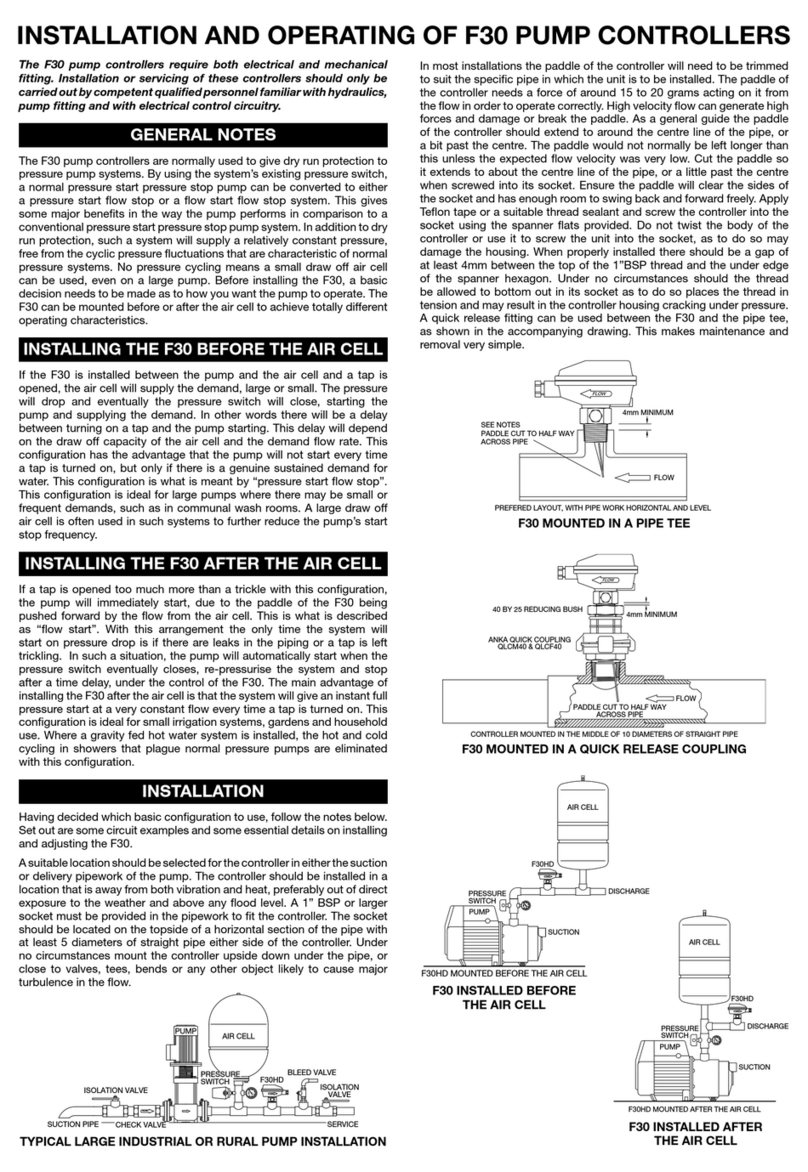
THE F30 PUMP CONTROLLER
The F30 Pump Controller offers a far better approach.
The pump starts on flow as soon as there is a modest
demand. When demand ceases the F30 continues to run
the pump for a settable length of time sufficient to
recharge the system’s air cell. Such a system allows the
selection of a pump that has a flat curve and delivers a
steady constant pressure over widely varying flows. An
air cell with a very small draw off can be used in such a
system. There only has to be sufficient stored pressure to
re-actuate the F30 controller the next time there is a
demand. With the F30 system the external pressure
switch is set to start the pump at a pressure only slightly
higher than the system’s static pressure. If the demand is
too low to actuate the F30’s paddle, or if for any reason
the pressure falls, eventually the pressure switch will
close and signal the F30 to start the pump. The F30 then
runs the pump for a preset time, recharges the air cell,
switches off the pump and reverts to standby mode.
DRY RUN PROTECTION
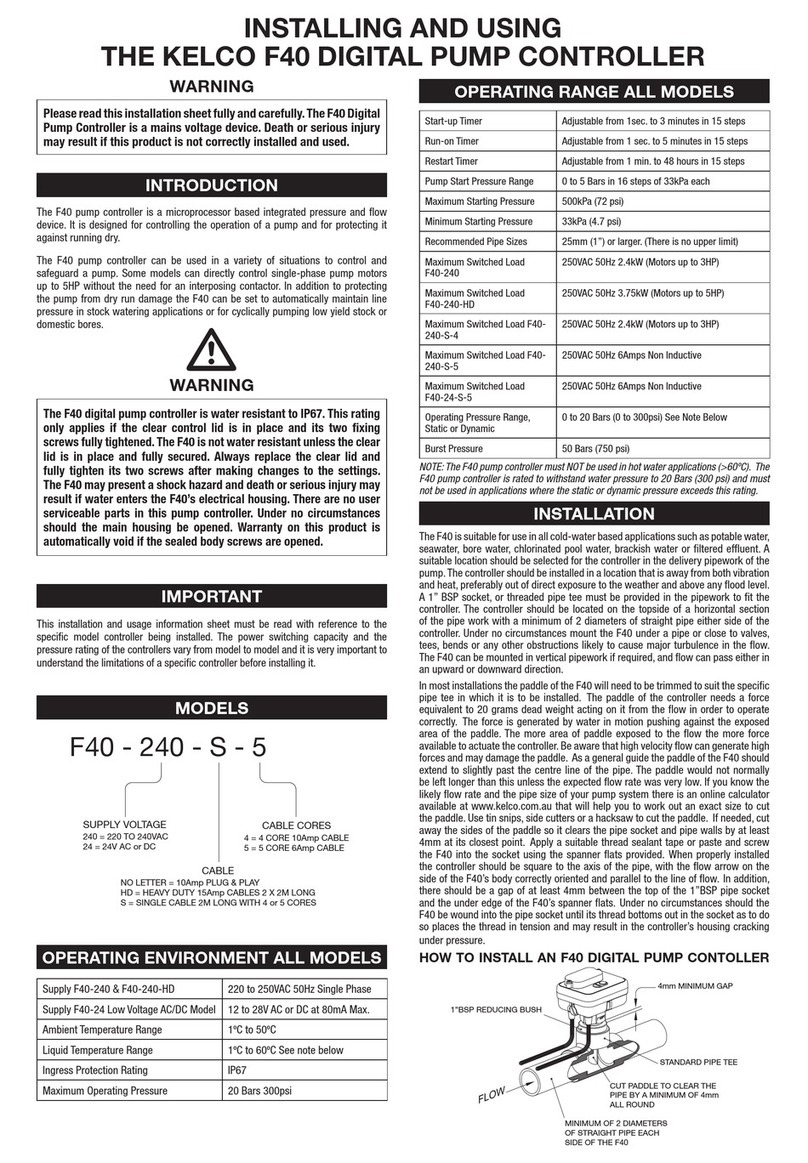
A pump running under the control of an F30 will start if the
pressure drops or if a tap is turned on. If the system
subsequently runs out of water the F30 senses the loss of
flow and the lack of pressure and immediately stops the
pump. A red warning light on the controller then flashes
rapidly to indicate there is a problem. The pump will not
restart until the power to the F30 is turned off and back on.
The pump will then run for a settable time and again test the
system for pressure and flow. If the pump is still running dry
the F30 will again automatically shut it down. If flow has been
restored the pump will continue to run until either the flow
demand ceases or until the system is fully pressurized.
Run on Timer Control
Start up Timer Control
Timer LED
Paddle and Alarm LED
Pressure switch LED

TECHNICAL DATA
CONSTRUCTION
The F30 controllers have no metal parts in contact with
liquids. They operate magnetically through their
thermoplastic housings. They are therefore ideally suited
to use in aggressive ground water, seawater or chlorinated
water and with a huge variety of chemical solutions
including most acids and alkalis.
The F30 is made from a blend of ABS and polypropylene
thermoplastics, specifically tailored to give the highest
possible performance, in terms of mechanical strength,
ultraviolet stability, and chemical inertness. All the F30
controllers use our well proven magnetic suspension
system, to give both a frictionless spring return action to
the paddle, and total isolation of the electronic module.
The microprocessor-based electronics built into the F30
have both brown out and over voltage protection built-in.
INSTALLATION
The F30 pump controller can be fitted to any type of pipe,
25mm (1 inch) diameter or larger and should be mounted
in a straight section of the pump’s discharge pipe,
downstream of the air cell. A 1"BSP female thread socket
or tee must be provided to fit the controller. To make
setting up the system simple, isolation valves and a bleed
valve should be fitted to the pump as shown in the
accompanying sketch.
TYPICAL INSTALLATION
SPECIFICATIONS
Microprocessor digital control.
Pressure switch input accepts a single switched active to
the AUX terminal.
Indicator LED shows when the pressure switch is open or
closed.
Fully independent control over both the start-up and run-
on timers.
Start-up timer adjustable from 0 to 180 seconds.
Run-on timer adjustable from 0 to 300 seconds.
True paddle status LED, turns on and off in response to
flow.
Power indication LED blinks to indicate the F30 is powered
up.
Timer LED indicates the start-up timer is running.
Dry run LED flashes to indicate the pump has shut down
on loss of flow.
Timer LED indicates the run-on timer is running.
Output to pump contactor is via 10Amp (resistive) 240V
S.P.D.T. voltage free relay contacts. (One set).
Brown out and voltage surge protection built-in.
Magnetic paddle adjustment for flow sensitivity.
Three M16 cable glands accept 8mm flex, or three M16
conduit connections.
Maximum operating pressure, static or dynamic, standard
models 18 Bars (260 PSI), 316 stainless models 100 Bars
(1400 PSI).
Maximum liquid temperature 80˚C.
Minimum liquid temperature –20˚C.
Liquid Ph 1 to 14.
Weatherproof rating IP56 (Hose proof).
145 89
32
62
24
165
PADDLE 28mm WIDE
1"BSP THREAD
M16
MADE IN AUSTRALIA BY
KELCO
ENGINEERING
Division of CYNCARD PTY LTD A.B.N. 20 002 834 844
Head Office and Factory: 9/9 Powells Road BROOKVALE 2100 AUSTRALIA
Postal Address: PO Box 496 BROOKVALE NSW 2100
Phone: 61 2 9905 6425 Fax: 61 2 9905 6420
Email: sales@kelco.com.au URL: www.kelco.com.au
PLEASE NOTE: Cyncard Pty Ltd reserves the right to change the specification of this product without notice. Cyncard Pty Ltd accepts no liability for personal injury
or economic loss as a consequence of the use of this product. All rights reserved copyright Cyncard Pty Ltd © 2003
FLOW
CHECK VALVE
ISOLATION VALVE
SUCTION PIPE
PUMP
SERVICE
PRESSURE
SWITCH
BLEED VALVE
AIR CELL
F30
ISOLATION
VALVE
MODELS AVAILABLE
DIMENSIONS
Model Description
F30-240 Standard all thermoplastic model for mains voltage operation
F30-24 Low voltage all thermoplastic model. For 24VAC operation
F30-12 12VDC model, for engine, battery or solar operation
316 Stainless steel body with 100 Bar pressure rating
1"NPT Male process connection
OPTIONS

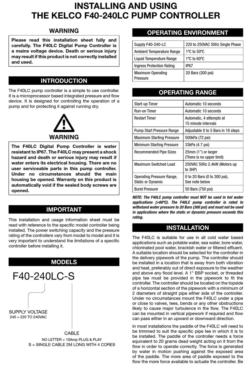
The F27 and F30 pump controllers require both electrical
and mechanical fitting. Installation or servicing of these
controllers should only be carried out by competent
qualified personnel familiar with hydraulics, pump fitting
and with electrical control circuitry. All electrical work
associated with the F27 and F30 controllers must be
carried out by qualified persons only. All wiring must
conform to the relevant local codes.
A suitable location should be selected for the controller
preferably in the discharge pipework of the pump. The
controller should be installed in a location that is away from
both vibration and heat, preferably out of direct exposure to
the weather and above any flood level. A 1" BSP or larger
socket must be provided in the pipework to fit the controller.
The socket should be located on the topside of a horizontal
section of the pipe with at least 5 diameters of straight pipe
either side of the controller. Under no circumstances mount
the controller under the pipe or close to valves, tees, bends or
any other object likely to cause turbulence in the flow.
The accompanying drawing shows an ideal set up with the
F27~F30 controller screwed into a 25mm by 40mm reducing
bush that in turn is screwed into an Anka quick coupling. The
coupling is then screwed into a 40mm pipe tee. A quarter turn
twist of the controller allows it to be removed from the pipework
without the need to disturb the wiring. Isolation valves should
be provided in both the suction and discharge pipes in all
installations to allow servicing and setting up of the system. We
recommend a small bleed valve be included in the discharge
pipe close to the pump and downstream of the controller.
In an F30 installation, dropping pressure to atmosphere
through this valve allows the pressure switch to be easily set
up and the controller’s time delay settings accurately
adjusted. By locating a bleed valve downstream of the
controller, the flow rate needed for actuation can be simulated
and accurately measured. Fine-tuning of the system is then
easily accomplished.
TYPICAL INSTALLATION WITH AN F30 CONTROLLING A
VERTICAL MULTISTAGE PUMP.
In most installations the paddle of the controller will need to
be trimmed to suit the specific pipe in which the unit is to be
installed. The paddle of the controller needs a force of 15 to
20 grams acting on it from the flow in order to operate
correctly. High velocity flow can generate high forces and
damage or break the paddle. As a general guide the paddle
should only extend to the centre line of the pipe, or a bit past
the centre. The paddle would not normally be left longer than
this unless the flow velocity will be very low. The paddle can
be trimmed in both length and width if required. Apply Teflon
tape or a suitable thread sealant and screw the controller into
the socket using the spanner flats provided. Do not twist the
body of the controller or use it to screw the unit into the
socket, as to do so may damage the controller.
When properly installed there should be a gap of at least
4mm between the top of the 1"BSP thread and the under
edge of the spanner hexagon. Under no circumstances
should the thread be allowed to bottom out in its socket as to
do so places the thread in tension and may result in the
controller housing cracking under pressure.
IDEAL INSTALLATION OF A CONTROLLER
TYPICAL 3-PHASE WIRING DIAGRAM
TYPICAL SINGLE PHASE WIRING DIAGRAM
INSTALLATION AND OPERATION OF F27 & F30 PUMP CONTROLLERS
FLOW
CHECK VALVE
ISOLATION VALVE
SUCTION PIPE
PUMP
SERVICE
PRESSURE
SWITCH
BLEED VALVE
AIR CELL
F30
ISOLATION
VALVE
FLOW
PADDLE CUT TO HALF WAY
ACROSS PIPE
4mm MINIMUM
ANKA QUICK COUPLING
QLCM40 & QLCF40
40 BY 25 REDUCING BUSH
40mm TEE
CONTROLLER MOUNTED IN THE MIDDLE OF 10 DIAMETERS OF STRAIGHT PIPE.
C
NO
NC
A
N
AUX
E
PUMP
MOTOR
N
E
TO CONTACTOR
OPTIONAL
EXTERNAL
ALARM
A
125mA
MAIN ISOLATION SWITCH
ISOLATION SWITCH, USE TO
RESET THE CONTROLLER
PRESSURE SWITCH
F30 MODELS ONLY
C
NO
NC
A
N
AUX
E
PUMP
MOTOR
A1
A2
A3
N
IMPORTANT
Adjust the pressure switch differential
pressure setting to a MINIMUM, so the
pressure switch OPENS as soon as the pump
starts. The pressure switch contacts must
open before the controllers run-on timer times
out. If the pressure switch fails to open before
the end of the time-out the controller will shut
down the pump and flash its red alarm LED
to indicate a dry run situation.
Normally Open pressure switch.
Set the pressure switch to close on a falling
pressure at 80 to 100kPa above the systems
static pressure.
F30 MODELS ONLY
E
TO CONTACTOR
OPTIONAL
EXTERNAL
ALARM
Isolation switch, use to
reset the controller.
125mA
F30
INSTALLATION

F30 12V DC WIRING DIAGRAM
The F27 and F30 controllers require a continuous stable supply
to their Active terminals. In most installations they will also need
an isolation switch to allow them to be reset. To protect the
controllers a 125mA fast blowing fuse should be placed in series
with the supply active. All controllers are protected from over
voltage by high amperage varistors that will blow the control
circuit fuse in the event of a voltage surge beyond the maximum
limits set out in the table below. Where possible ensure the
control circuit is not on the same phase as the pump motor. This
is particularly important where long cable runs are involved.
Voltage drop from the pump motor starting may cause the
controller to reset, or its output relay to chatter and cause the
pump to jog. Jogging can snap a pump shaft very quickly, so
please take all precautions to ensure the supply to the controller
is stable and adequate for the job. Supply voltage must be
within the limits set out in the table below.
SUPPLY VOLTAGE
MODEL MAXIMUM MINIMUM SWITCHED
SUPPLY SUPPLY SUPPLY
VOLTAGE VOLTAGE TO AUXILIARY
F30-240 260VAC 160VAC 160 to 260VAC
F30-24 28VAC 18VAC 18 to 28VAC
F30-12VDC 15VDC 10VDC 10 to 15VDC
F27-240 260VAC 160VAC 160 to 260VAC
F27-24 28VAC 18VAC 18 to 28VAC
Note: Current draw with their internal relay energised is
<85mA for all F27 and F30 controllers.
All the controllers use an inbuilt relay as their output. The
contacts of the relay are voltage free. The relay contacts are
rated at 250VAC at 10Amps resistive. To ensure a long
reliable life from the controllers we recommend all pump
motor control should be via a suitable contactor.
The F30 controllers require an input from an external
pressure switch located in the discharge pipework of the
pump. The F30 accepts a switched input to its AUX terminal
that is at the same voltage, and derived from the same phase
as the main supply to the F30. The current draw through the
pressure switch is <5mA. Series connect the pressure switch
contacts between the control circuit active and the AUX
terminal. Use only the contacts that close on a falling
pressure, that is, the low-pressure cut in contacts. If the
switch has duel poles, connect both sets of contacts in
parallel to reduce the resistance path through the switch.
Details on setting up and adjusting the pressure switch can be
found further on.
LAYOUT OF THE CONTROLS AND INDICATOR LIGHTS
PADDLE FUNCTION
LIGHT
TIMER FUNCTION
LIGHT
F30 CONTROLLERS ONLY
AUXILIARY FUNCTION
LIGHT
C
NO
NC
AUX
E
PUMP
MOTOR
-
+
+
-
12v DC Supply
SUPPLY TO PUMP
AC or DC
125mA
PRESSURE
SWITCH
ISOLATION SWITCH.
USE TO RESET THE
CONTROLLER
CONTACTOR
5
30
60
60
5
0
30
TIMER
PADDLE
RUN-ON
TIMER
START-UP
TIMER
SECONDS
NOCNC ANE
AUX
AUXILIARY ONLY ON THE F30, THIS LIGHT TURNS
ON WHENEVER THE PRESSURE SWITCH
CONTACTS CLOSE.
THIS LIGHT TURNS GREEN WHEN THE START-UP
TIMER IS RUNNING AND TURNS RED WHEN THE
RUN-ON TIMER IS RUNNING
THE START-UP TIMER IS ADJUSTABLE FROM 1 SECOND TO
3 MINUTES AND IS USED TO GET THE PUMP STARTED IN
SPITE OF NO FLOW.
THIS LIGHT INDICATES THE TRUE POSITION OF THE PADDLE.
IT TURNS GREEN WHENEVER THE PADDLE IS ON. ON THE F30
IT ALSO FLASHES RAPIDLY RED TO INDICATE IF THE PUMP
HAS RUN DRY.
START-UP TIMER
AUXILIARY
TIMER
PADDLE
RUN-ON TIMER
THE RUN-ON TIMER SETS HOW LONG THE PUMP RUNS ON
AFTER FLOW STOPS. ON THE F30 IT ALSO SETS HOW LONG
THE PUMP RUNS AFTER THE PRESSURE SWITCH CLOSES.
IT IS ADJUSTABLE FROM 1 SECOND TO 5 MINUTES.
IT BLINKS SLOWLY RED IN STANDBY MODE
WHENEVER THE POWER IS ON.
Green
Slow
Red
Pulse
Rapidly
Flashing
Red
Indicates that the paddle is in the on position.
Normally off, this light turns green as soon as flow
pushes the paddle into the on position. The pump
will be on whenever this light is green
Blinks every two seconds to indicate power is on to
the controller. This light will slowly blink red
whenever the power is on but the pump is off.
On the F30 controllers only, this light flashes rapidly
red indicating that the pump has run dry and the
controller has shut down the pump due to lack of
pressure. Normally the blue auxiliary light will also
be on, indicating that the pressure is too low.
Green
Red
Provided the start-up timer is set to some value
other than zero, this light Indicates that the start-up
timer is running, only comes on when the controller
is first powered up. The pump will run while ever
this light is on.
Indicates that the run-on timer is running. Can only
come on after the start-up timer has timed out.
Provided the run-on timer is set to some value
other than zero, this light will switch on whenever
the paddle swings to the off position. On an F30
controller it will also switch on whenever the
pressure switch contacts close. The pump should
be running while ever this light is on.
Blue
This light indicates the true status of the remote
pressure switch. It is on when ever the contacts of
the pressure switch are closed. The pressure
switch contacts must be open and this light off
before the run-on timer times out. If not, the
controller will shut down the pump and go into
alarm mode and the red paddle light will flash
rapidly. The pump will not restart until power to the
F30 is reset.
ELECTRICAL
WIRING IN THE PRESSURE SWITCH
FUNCTIONS OF THE INDICATOR LIGHTS

The F27 controller is a conventional 1" BSP paddle flow
switch with a built in micro electronic controller that gives a
fully adjustable override on start function and an
independently adjustable paddle bounce ignore, or run on
function. A pump under the control of an F27 can start in
spite of no initial flow; it will ignore paddle bounce and can run
on for up to 5 minutes after flow stops. The run on function is
very useful for pressurising air cells and for pumping down
low yield bores.
The F30 pump controller operates in exactly the same way as
the F27 but in addition can accept an input from an external
pressure switch. The auxiliary input allows the F30 to read both
flow and pressure, and means that a pump under its control will
start automatically on a pressure drop as well as on a flow
demand. By monitoring pressure the F30 can identify a dry run
situation and shut down the pump. The F30 is very versatile
and can be used in many innovative ways in automatic tank
filling systems and in industrial pump control.
Time delay adjustment is by means of two 16 position rotary
switches. The time delays are individually programmed into
the controllers to give the rotary switches the following delays.
TIMER DELAY IN SECONDS
Start up Timer 0, 1, 2, 3, 4, 5, 10, 15, 20, 25, 30, 40, 50, 60, 120, 180
Run on Timer 0, 1, 2, 3, 4, 5, 10, 15, 20, 25, 30, 40, 50, 60, 180, 300
ADJUSTING TIMER SETTINGS
After adjusting the timer settings, the power to the controller
must be reset, that is, it must be turned off for a minimum of
0.5 seconds and then turned on again, before any changes
will take effect. This applies to all the controllers under all
operating conditions.
BASIC FLOW SWITCH FUNCTION
Both the F27 and F30 pump controllers have two independent
timers and are individually adjustable in steps. With both
timer dials set to zero, the controllers behave like a basic flow
switch and respond solely to paddle movement. On power up,
the only indication of activity will be the paddle light slowly
blinking red to indicate the power is on. If the paddle is
pushed into the on position, the output relay will energise and
the paddle light will turn green. If the paddle swings to the off
position the output relay de-energises immediately, the pump
will stop and the paddle light will revert to slowly blinking red.
OVERRIDE ON START
Set the run-on timer to zero. Set the start-up timer to 5
seconds. Reset the power for the change to take effect. On
power up the pump should start. The green timer light will
come on and stay on for the 5 seconds. If the paddle is
pushed into the on position the main green paddle light will
come on. At the end of the time out, the green timer light will
go out but if the paddle is on the pump will continue to run. If
the paddle then swings to the off position the paddle light will
turn off and the pump will stop. The start-up timer should be
set to a few seconds longer than the time it takes for the
paddle light to come on. By watching the timer and paddle
lights on power up, it is a simple matter to correctly set the
start-up timer.
RUN-ON TIMER
Set both the start-up and run-on timers to 5 seconds. On
power up the pump should start and the green timer light
should come on. If the paddle swings into the on position the
green paddle light will also come on. After 5 seconds the green
timer light will go out but the pump will continue to run and the
paddle light will remain green. If the paddle then swings to the
off position the green paddle light will go out and the timer light
will turn on red indicating the pump is running on the run-on
timer. The pump will continue to run while the run-on timer is
running. If the paddle swings back to the on position before the
run-on timer times out, the pump will continue to run
seamlessly. If the paddle fails to return to the on position within
the 5 seconds the pump will stop. The run-on timer’s red light
will go out and the green paddle light will also go out. Every
time the paddle swings back to the off position the run-on timer
will re-run and keep the pump running while it times out.
Set the pressure switch so its low-pressure contacts close on
a falling pressure at 8 to10M head or 80 to 100kPa above the
systems static pressure. In a pressurised system with a slow
bleed off the pressure switch contacts must close before all the
pressure leaches away. In addition, the pressure switches
differential setting must be set to a minimum. The object is to
have the pressure switch start the pump only and then for its
contacts to open as soon as the pressure starts to rise and
before the run-on timer times out. If the recommended bleed
valve and pressure gauge have been included in the
installation the job of adjusting the pressure switch and testing
the system is made very simple.
Given that the pressure switch has been correctly adjusted, an
F30 will function in the following manner. The paddle light will
blink slowly red indicating power is on. If the bleed valve is
slightly opened so as not to actuate the paddle then as soon
as the pressure reaches the cut in pressure of the pressure
switch and its contacts close, the pump starts. The blue
pressure switch light and the red run-on timer light will turn on.
As the pressure rises, the pressure switch contacts should
open, the blue light will go out and the pump will continue to
run under the control of the run-on timer. When the run-on
timer times out the pump will stop and the red run-on timer
light will go out. The paddle light will again blink slowly red.
The net effect has been to re-pressurise the system. If the
pressure is allowed to leach away again, the process will
repeat and then the F30 will return to standby mode.
It is important to note that the pressure switch is only used to
start the system, not to stop it as in a conventional pressure
system. The result is a constant pressure system not
constrained by the need to pump up to a high cut out pressure
simply because the pressure switch requires it. A multi stage
pump can be de-staged, or a pump with a substantially flat
constant flow curve can be selected to operate under the
control of the F30. This can result in substantial savings in
running costs and in many applications provide a highly
useful constant pressure flow, essentially free of the pressure
fluctuations that plague conventional pressure systems.
The first time the system is started, the pressure switch contacts
will be closed, due to lack of pressure. When power is applied,
the pressure switch will control the start-up timer and not the
run-on timer. Only after the initial time out of the start-up timer
does the pressure switch control the run-on timer. It is important
to understand this, because it means that the start-up timer will
need to be set to a value slightly longer than the time it takes for
TIMER SETTINGS
F27 PUMP CONTROLLER
F30 PUMP CONTROLLER
SETTING UP THE PRESSURE SWITCH
F30 DRY RUN PROTECTION

the pressure switch contacts to open. After this initial startup,
and once the system has stabilized, closing of the pressure
switch will trigger the run-on timer and not the start-up timer. In
normal operation, if the pressure falls and the pressure switch
contacts close, it will be the run-on timer that determines the
time the pump runs for. During the initial start up, if the start-up
timer times out before the pressure switch contacts open the
controller will go into alarm mode and the pump will stop.
The same effect will occur when recovering from a dry run lock
out situation. That is, with the system in alarm mode, resetting
the power will start the pump, but it will be the start-up timer
that the pressure switch is controlling and not the run-on timer.
Only after the initial time out of the start-up times will the
system get back into its normal mode where subsequent
closing of the pressure switch triggers the run-on timer.
The start up timer needs to be set to a value that lets the
pressure rise sufficiently to open the pressure switch contacts.
It doesn’t need to be sufficient time to fully pressurize the
system, just enough to get it started. Subsequent closing of
the pressures switch will trigger the run-on timer and it is its
longer cycle that will fully charge the system.
The F30 will start a pump on a falling pressure, and it expects to
see the pressure rise as soon as the pump starts. At any time,
during normal running or during standby, the closing of the
pressure switch contacts will start the run-on timer running. If
the run-on timer times out and the pressure switch contacts
have not opened, the F30 will go into alarm mode. The pump
will stop and the paddle light will turn red and flash rapidly. In
alarm mode the paddle is overridden and even if it is jammed in
the on position the pump will not run. Normally in this situation,
the blue pressure switch light will also be on, indicating that the
pressure switch is closed and therefore the pressure is too low.
To restart the pump, turn the power off wait half a second and
turn it back on. If the pump is running dry, the F30 will again
time out on its main timer, stop the pump and go back into
alarm mode. With the pump primed, reset the power and
observe the blue pressure switch light. As the pressure rises
the blue light will go out and the pump will continue to run
under the control of the main timer. When the timer times out
the pump will stop and the paddle light will revert to slowly
blinking red, indicating all is well and the controller is in
standby mode. If the recommended isolation and bleed valves
have been included in the installation the dry run protection
system can be tested by opening the bleed valve and shutting
off the pump suction isolation valve while the pump is running.
A sensitivity adjusting screw is provided for fine-tuning the
controllers. Under the end of the controllers housing is a hex
headed plug that covers the adjusting screw. Remove the plug
and using a broad bladed screwdriver wind the adjusting
screw anticlockwise to increase the sensitivity (reduce the flow
rate needed to actuate the paddle.) As supplied the screw is
wound fully in, and the controller set to its least sensitive.
The maximum sensitivity is reached with the screw wound out
to a point where the hex dust cover can still be refitted. Normally
the sensitivity screw should be left fully in. If the paddle has
been trimmed too short, the effect can be compensated for by
winding the sensitivity screw out a few turns.
An F30 pump controller can be used in many novel ways to
control a pump. The schematic below shows how to use a single
external timer to restart a borehole pump that has dropped
out on loss of prime, due to low yield or high draw down.
AUTO RESTART OF A TANK FILLING SUBMERSIBLE BORE PUMP
A single external timer can be used to control the AUX
terminal of an F30 that in turn restarts a pump after any
required time delay. With reference to the accompanying
schematic, when the tank level switch closes it powers up
the F30 and immediately energises the pump contactor, and
starts the pump. The Normally Closed auxiliary terminals of
the contactor will open, so there will be no power to the
external timer. If the F30 drops the contactor out because of
lack of flow, the contactors auxiliary terminals will close and
power up the external timer. The timer will run for whatever
it is set to, say 2 hours, before its contacts close and power
up the auxiliary terminal of the F30, restarting the F30 and
the bore pump. As soon as the pump starts, power is lost to
the external timer and its contacts open, dropping the power
off the F30 auxiliary terminal. The bore pump runs on under
the control of the F30. If the bore draws down again, the
process will repeat with the pump restarting at whatever
time interval has been set on the external timer. If the bore
is still dry when the external timer powers up, the pump will
only run for the time set on the F30 main timer, a maximum
of 180 seconds. In a normal situation the bore will recover
during the external timer’s delay, however if the bore
remains dry it is highly unlikely that the short and infrequent
run time of the F30 will cause any damage to the bore pump,
and the user will become aware of the problem when he
runs out of water in the tank.
C
NO
NC
A
N
AUX
E
N
E
A
LEVEL SWITCH
PUMP CONTACTOR
N/C AUX CONTACTS ON DELAY TIMER
F30 CONTROLLER
125mA
ISOLATION SWITCH
SENSITIVITY ADJUSTMENT
HOW TO CONTROL A LOW YIELD TANK
FILLING BORE PUMP
Made in AUSTRALIA by KELCO ENGINEERING
Division of CYNCARD Pty Ltd A.B.N. 20 002 834 844
Head Office and Factory: 9/9 Powells Road BROOKVALE 2100 AUSTRALIA
Postal Address PO Box 496 BROOKVALE NSW 2100
Phone: 61 2 99056425 Fax: 61 2 99056420 Email: sales@kelco.com.au URL: www.kelco.com.au
PLEASE NOTE Cyncard Pty Ltd reserves the right to change the specification of this product without notice. Cyncard Pty Ltd accepts no liability
for personal injury or economic loss as a consequence of the use of this product. All rights reserved copyright Cyncard Pty Ltd C 2003
Table of contents
Other KELCO Controllers manuals

KELCO
KELCO PG20 Series Instruction Manual

KELCO
KELCO F40 Series Guide

KELCO
KELCO F60 MK3 Assembly instructions

KELCO
KELCO F60 Mk2 Assembly instructions

KELCO
KELCO F60 Installation manual

KELCO
KELCO F40-240LC Guide

KELCO
KELCO F29 MK3 Assembly instructions

KELCO
KELCO F60 User manual

KELCO
KELCO F30 User manual