FIBER SENSYS Fiber Defender FD508 User manual

PM-ENG-040 Rev F Confidential –Limited Distribution
© Copyright 2014, Fiber SenSys® all rights reserved. No part of this publication
may be reproduced or transmitted in any form or by any means, electronic or
mechanical, including photocopy, recording, or any information storage and
retrieval system, without permission in writing from Fiber SenSys®, Inc., 2925 NW
Aloclek Drive, Suite 120, Hillsboro, Oregon 97124, USA.
Fiber Defender FD508™
User Manual

Page 2 Confidential –Limited Distribution
This manual is provided by Fiber SenSys Inc. While reasonable efforts have been
taken in the preparation of this material to ensure its accuracy, Fiber SenSys Inc.
makes no express or implied warranties of any kind with regard to the
documentation provided herein. Fiber SenSys Inc. reserves the right to revise this
publication and to make changes from time to time in the content hereof without
obligation of Fiber SenSys Inc. to notify any person or organization of such
revision or changes.
FD508TM is a trademark of Fiber SenSys Inc. (FSI)
Fiber SenSys®is a registered trademark of Fiber SenSys Inc.
Windows®is a registered trademark of Microsoft Corporation.
Fiber SenSys Inc.
2925 NW Aloclek Dr.
Suite 120
Hillsboro, OR 97124
USA
Tel: 1-503-692-4430
Fax: 1-503-692-4410
info@fibersensys.com
www.fibersensys.com

FD508TM User Manual Page 3
Table of contents
1. Introduction .........................................................................................................4
2. Safety information ...............................................................................................5
Safety terms ...................................................................................................5
Electrical safety...............................................................................................5
Covers and panels..........................................................................................5
Inspection.......................................................................................................6
Laser radiation................................................................................................6
Fiber-handling precautions..............................................................................6
FCC rules .......................................................................................................7
3. The Sensing Fiber...............................................................................................8
Fiber Optic Sensing ........................................................................................8
Types of Installations......................................................................................8
Connectors.....................................................................................................8
System Configuration......................................................................................9
4. The Alarm Processing Unit (APU) .....................................................................11
APU Description ...........................................................................................11
Installing the APU into the Rack....................................................................12
5. Tuning the Zones ..............................................................................................13
Start 500 Series View ...................................................................................13
APU Parameters Tab....................................................................................13
HyperZone Tuning........................................................................................15
Assigning a Device Name.............................................................................18
Help Menu ....................................................................................................18
The Realtime Tab.........................................................................................18
6. Integrating the APU into the Security System....................................................21
7. Testing and certification.....................................................................................22
8. Maintenance......................................................................................................23
Appendix A. Product Specifications........................................................................24
Appendix B. Auxiliary Software Features................................................................25
Appendix C. Warranty Information..........................................................................26
Appendix D. Referenced Documents .....................................................................27
Fiber Defender FD508TM User Manual 4
1.Introduction
The FD508 Alarm Processing Unit (APU) is a fiber optic sensor designed to detect potential
intruders that are trying to breach a perimeter. The APU is capable of detecting multiple
simultaneous disturbances along a protected perimeter. One APU fits into a 1-U space in a
standard 19-inch rack, and can monitor up to eight different sensing fibers (zones).
The FD508 detects intruders using a fiber optic sensor that is deployed on the perimeter. For
perimeters with chain-link fencing, the fiber is installed inside conduit that is tied to the fence
with stainless steel wire ties. The sensing fiber can also be deployed on decorative metal
fences, cement walls, etc. The fiber optic sensor works by measuring modulated laser radiation
that results from potential intruders who vibrate the structure to which the fiber is attached.
When the FD508 detects intruders, it sends alarm messages to a head end, and can also switch
relay contacts that can be used to manage lights, cameras, audible alarms, etc.
The optical fiber-based system has been designed to be
immune
to the effects of
Electromagnetic Interference
(
E
M
I), lightning, and Radio
Frequency
Interference (RFI). The
FD508 provides maximum effective
intrusion
detection through its inherent system flexibility and
advanced programmability.
Because the fiber optic sensors use laser light which is intrinsically inert, the FD508 system can
be installed safely at chemical plants, ammunition depots, or any location where the use of
electricity is a concern.
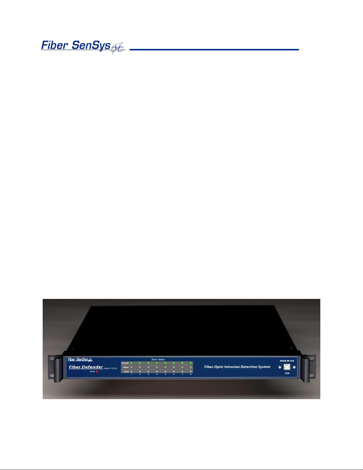
Figure 1-1 shows the front of the FD508. The front of the APU has indicator lights that show the
status of each zone; a steady green light indicates normal/secure operation, and red lights come
on during an attempted intrusion (alarm), or if the fiber is cut (fault).
Figure 1-1. Front view of the FD508 APU.

Fiber Defender FD508TM User Manual 5
2.Safety Information
This section contains information to help ensure your personal safety and the proper operation
of your equipment. Please follow these instructions carefully, and keep them accessible, for
future reference. Whenever using the FD508, use only attachments and accessories that have
been specified by FSI, and refer all servicing to qualified personnel.
Safety Terms
The following icons may appear throughout this manual:
CAUTION: Identifies conditions or practices that could result in damage to equipment
and/or loss/contamination of data.
WARNING: Identifies conditions or practices that could result in non-fatal personal injury.
DANGER: Identifies conditions or practices that could result in serious injury or death.
Electrical Safety
If the FD508 is damaged or malfunctions, disconnect power to the APU. Do not use the
APU if any of the following conditions exist:
•The APU is damaged.
•The APU does not operate as expected.
•The APU has been subjected to prolonged storage under adverse conditions.
Do not put the APU into service until qualified service personnel have verified its safety.
Covers and Panels
There are no user-serviceable parts inside the APU. To avoid personal injury, do not
remove any of the APU’s covers or panels. The product warranty is void if the factory seal
is broken. Do not operate the product unless the covers and panels are installed.

Fiber Defender FD508TM User Manual 6
Inspection
The FD508 APU should be inspected for shipping damage. If any damage is found, notify
Fiber SenSys and file a claim with the carrier. Save the shipping container for possible
inspection by the carrier.
Laser Radiation
The FD508 APU is a Class 1 laser product, as defined by IEC 60825-1 and CFR 21
subchapter J. A Class 1 laser emits insufficient light to constitute a hazard. However, avoid
direct eye exposure to the output of this product or to the open end of any optical-fiber
cable connected to this product.
The following stamp is found on the rear panel of the FD508 APU:
Figure 2-1. Class 1 laser stamp on rear panel of the FD508 APU
Fiber-Handling Precautions
Warning: Optical fibers are made of glass, and the ends of broken fibers can be sharp and
may become lodged in the skin. Take appropriate handling precautions.

Fiber Defender FD508TM User Manual 7
FCC Rules
Note: This equipment has been tested, and complies with the limits for a Class B digital
device, pursuant to Part 15 of the FCC Rules. These limits are designed to provide
reasonable protection against harmful interference in a residential installation. This
equipment generates, uses, and can radiate radio-frequency energy. If the equipment is
not installed and used in accordance with the instructions, it may cause harmful
interference to radio communications. However, there is no guarantee that interference will
not occur in a particular installation. If this equipment does cause harmful interference to
radio or television reception, which can be determined by turning the equipment off and on,
the user is encouraged to try to correct the interference by one or more of the following
measures:
•Reorient or relocate the receiving antenna.
•Increase the separation between the equipment and receiver.
•Connect the equipment into an outlet on a circuit different from that to which the receiver
is connected.
•Consult the dealer or an experienced radio/TV technician for help.

Fiber Defender FD508TM User Manual 8
3.The Sensing Fiber
The FD508 detects intruders by sensing small disturbances caused by vibrations induced within
a fiber optic sensor attached to the perimeter. The optical sensor is a thin strand of multimode
optical fiber inside a specially designed 3 mm fiber optic cable. The fiber optic cable should be
installed in such a way that, when intruders attempt to cross the perimeter, they create slight
vibrations that disturb the sensing fiber. These disturbances are then detected by the FD508
APU, which generates the appropriate alarm(s).
Fiber Optic Sensing
When an optical fiber is exposed to vibration, the vibrations cause small asymmetric
changes in the fiber’s density. In turn, these changes in density cause measurable
changes in certain characteristics of laser radiation transmitted through the fiber. The
FD508 uses precision lasers and detectors, along with sophisticated digital signal
processing, to measure these changes in the laser radiation. The processor analyzes the
incoming signals in order to determine whether they are caused by intruders, or harmless
nuisances, such as vibrating equipment. To learn more about fiber optics and their use as
sensors, refer to the fiber optics application note titled: AN-SM-007 Fiber Optics.
Types of Installations
There are many different ways to use the FD508 system. The most common installation is
on chain link fence. For fence-mounted applications, the fiber-optic cable is installed inside
a flexible conduit, which is then secured to the fence using stainless steel wire ties. Other
applications involve installing the optical cable inside the channels of decorative metal
fence, or running the flexible conduit (with optical cable inside) along the tops of concrete
walls. For detailed information about the possible fenced perimeter installations, and site
design techniques, see the application note on site design and assessment titled: AN-SM-
036 FD500 Series –Site Design and Assessment.
Connectors
The FD508 is a time-domain-multiplexed system that can monitor up to eight fully
independent zones (sensing fibers) using a single APU. To maintain a high signal-to-noise
ratio, it is important that all optical connections in the system be made with either fusion
splices or angled physical-contact (APC) fiber optic connectors. PC and UPC connectors
should not be used. For more information about fiber optic connectors, refer to the fiber
optics application note: AN-SM-007 Fiber Optics.

Fiber Defender FD508TM User Manual 9
System Configuration
Each zone in the system connects to an optical port on the back of the APU. Typically,
1
each zone consists of an insensitive lead-in fiber which connects to the sensing fiber. All
sensing fibers used with the FD508 are “single ended,” so there is no need to loop the
sensing fiber back to the APU. Instead, the far end of the sensing fiber is terminated with a
special termination unit, called the Multimode End-Of-Line (MMEOL) terminator.
Fiber SenSys provides a trunk cable that can carry the insensitive lead-in fibers to all the
zones. At points where a zone is desired, specialized tools can be used to cut into the
trunk cable to expose one of the insensitive lead-in fibers which is then spliced to sensing
fiber (see figure 3-1); this technique is known as a “mid-entry.”The splice point is fully
enclosed in a breakout box which serves as a splice enclosure and is sold as a complete
kit, including the MMEOL.
2
For more information on installing the trunk cable, sensors, and
MMEOL, see the application note on installing perimeter fiber optic cable: AN-SM-035
FD500 Series –Standard Installation Instructions.
Figure 3-1. Typical system configuration. The trunk cable contains the insensitive fibers. The breakout boxes act
as splice enclosures, protecting the points where the trunk cable is broken into, when splicing the insensitive
lead-in fiber to the sensing fiber. The MMEOL is spliced onto the end of the sensing fiber. The three red dots
indicate that the trunk cable continues on to other breakout boxes and other sensing fibers.
1
It is possible to connect the sensing zones directly to the APU, in which case the trunk cable need not
be used. Typically, however, it is desirable to place the APU in a location separate from the perimeter,
and to connect the APU to the sensing fibers via the insensitive fibers in the trunk cable.
2
Each breakout box can support up to two zones.

Fiber Defender FD508TM User Manual 10
All zones must be properly installed and terminated before connecting to the APU. In
addition, it is helpful to test the optical loss of each zone. Optical loss, however, must be
tested before the termination units are installed on the ends of the zones (the termination
units are not transmissive). Also, each zone should be numbered, and a label with the
zone number affixed to the fiber near the connector that will plug into the APU.
The insensitive lead-in fibers plug directly into the APU, and are always connected with an
angled polished SC connector (SC/APC). The FD508 can support up to eight fully
independent sensing fibers, or zones. However, these zones must be connected to the
APU in a specific order, as determined by the Port Assignment software. For more on the
Port Assignment software, see the application note: AN-SM-023 Port Assignment Wizard.
Fiber Defender FD508TM User Manual 11
4.The Alarm Processing Unit (APU)
APU Description
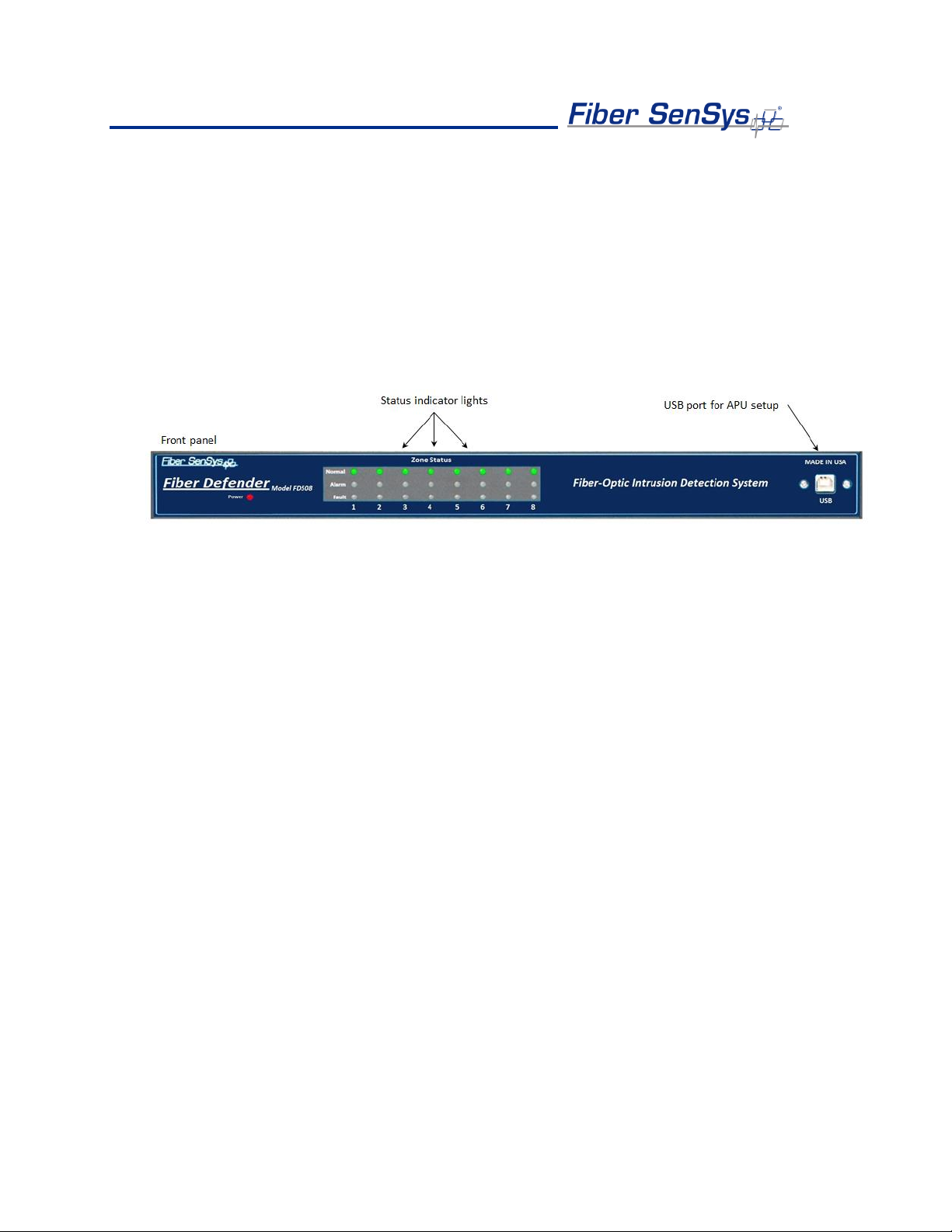
The front of the APU has indicator lights that provide a quick, visual indication of the status
of each zone. Until the APU is properly configured, all the red “alarm” and “fault” lights will
be lit; after the APU is properly configured and under normal operation, the green “normal”
lights will be all lit.
Figure 4-1. Front panel of the FD508 showing the status indicator LEDs and USB port.
The FD508 can support up to eight zones. After the zones are connected, and the APU
has been properly configured, when the APU detects an alarm on a particular zone, the
green “normal” light goes out and the red “alarm” light comes on. The red “alarm” light does
not latch; it goes out when the attempted intrusion ends. If a zone is cut, the green “normal”
light goes out and the red “fault” light comes on until the zone is repaired.
In addition to the status lights, the front of the APU has a USB port. This port is used to
connect the APU to a computer for configuring and tuning the zones. Tuning is a process
of adjusting different parameters that are used by the intruder-detection algorithms.
Through the tuning process you can adjust the overall sensitivity of the zones (each zone
can be independently tuned) as well as parameters that help to reject nuisance alarms.
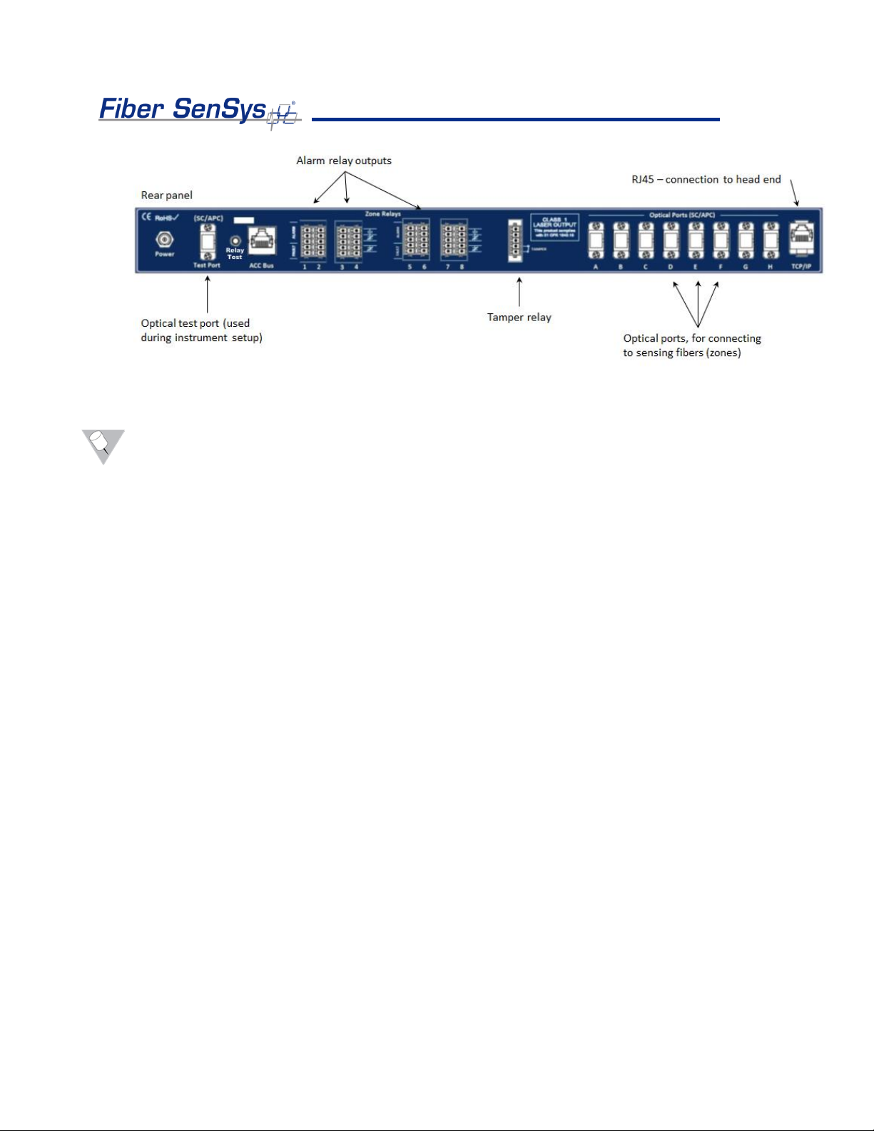
All in-service connections to the APU are made through the rear panel (see figure 4-2).
These connections include:
1. Eight optical ports for the fiber optic sensors that go to each zone.
2. Relay outputs for each zone.
3. Optical test port (for initial setup). Not used after commissioning the system.
4. Tamper input.
5. TCP/IP port via RJ45 connector.
6. DC power input jack.
Fiber Defender FD508TM User Manual 12
Figure 4-2. Rear panel of the FD508. The test port is located on the extreme left-hand side. The optical ports
that will eventually be connected to the zones are labeled A-H, and are located on the right-hand side.
Note: It is important that you only insert clean optical connectors into the APU’s test port.
Dirty connectors can degrade the performance of the APU, or even cause irreversible
damage. When laying connectors down, unconnected, make sure they have protective
caps on the ferrules. Caps protect the ferrule from damage that might be caused by
bumping the ferrule against a foreign object, but caps can be dirty, and don’t protect
(effectively) against microscopic contamination. Consequently, be sure to clean all
connectors prior to insertion into the alignment port, whether or not they have been capped.
For more information on the care and cleaning of fiber-optic connectors, refer to the fiber
optics application note: AN-SM-007 Fiber Optics.
Installing the APU into the Rack
The APU comes with a rack-mounting that consists of two rack-mounting handles and
screws for attaching them to the APU. Attach the handles to the APU, and then mount the
APU into the rack by the rack-mounting handles.
Fiber Defender FD508TM User Manual 13
5.Tuning the Zones
The tuning software is called 500 Series View; it runs on a PC that is connected to the APU
via the USB port on the front of the APU. 500 Series View is a Windows-based software
application for system tuning and calibration; this software is used for maximizing sensitivity
when detecting intrusions while minimizing nuisance alarms. 500 Series View can also be
used for monitoring system performance, recording sensor data, and analyzing stored data.
Start 500 Series View
With the APU’s power off, connect one end of a USB cable to the APU, and the other end
to the PC from which you will be launching 500 Series View; then power on the APU.
Launch the 500 Series View software by clicking on the software icon shown below, from
the 500 Series Suite launch page:
Upon launching the program, the APU is automatically detected and a connection is made.
After connecting, 500 Series View starts up with the APU Parameters tab selected, and
the screen displays the tuning parameters that are currently stored in the APU.
APU Parameters Tab
The parameters tab (see figure below) is where you:
1. Define the tuning parameters for each HyperZone.
2. Assign zones to HyperZones.
3. Write parameters to the APU.
4. Rename zones.
5. Assign a device name to the APU.
6. Define the XML report interval.

Fiber Defender FD508TM User Manual 14
Figure 5-1. The 500 Series View AP Parameters screen
When tuning the APU, the parameters are assigned to HyperZones; each zone that is
placed into a HyperZone is automatically given the tuning parameters of that HyperZone.
HyperZones are a tool for making the tuning process easier; instead of individually entering
the tuning parameters for each zone, the parameters can be altered by simply placing
(dragging) that zone into the appropriate HyperZone (parent node).
Whenever making changes to the tuning parameters, the changes will not take effect until
they are written to the APU. To write the new parameters to the APU, click the Write
button, in the APU Parameter Control group.
CAUTION: When tuning a given HyperZone, do not select another HyperZone before
clicking on the Write button. If you change HyperZones, or close 500 Series View, before
saving the tuning parameters, all new parameters will be lost.
The number of HyperZones can be as high as 8 (in which case each zone is in its own
HyperZone) or as low as one (in which case all the zones have the same tuning
parameters).
Fiber Defender FD508TM User Manual 15
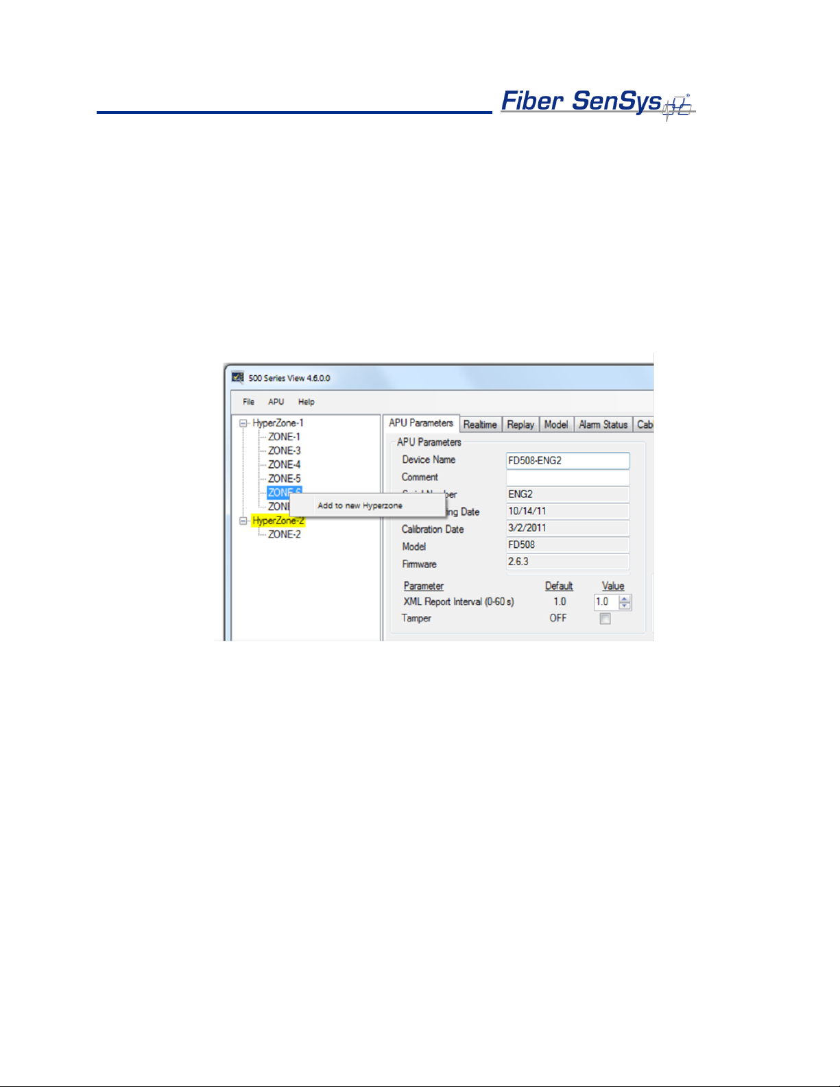
When 500 Series View is first launched, all of the zones are contained within a single
HyperZone. To create a new HyperZone, and place a zone into it, click on the APU
Parameters tab and right click on the zone to be moved. Select the popup Add to new
HyperZone when it appears. This will create a new HyperZone and place the selected
zone into it. When a new HyperZone is created, the parameters of the new HyperZone are
identical to the parameters of the original until being changed by the user.
The process can be continued by right-clicking over other zones and creating additional
HyperZones. Zones can be moved by dragging them and dropping them from one
HyperZone tree to another.
Figure 5-2. Creating a new HyperZone
HyperZone Tuning
The tuning parameters are found in the lower right-hand corner of the 500 Series View
APU Parameters screen. Generally, these tuning parameters will change from one
HyperZone to the next. To change the tuning parameters, highlight the HyperZone either by
double clicking it, or by right clicking on it and choosing Select from the pop-up menu (see
figure 5-1).
With the HyperZone selected, change the value of any tuning parameter using either the
arrow keys or by typing a new value into the associated box and pressing Enter. If the
allowable range is exceeded, 500 Series View automatically changes the entry to the
closest allowed value.
Fiber Defender FD508TM User Manual 16
Each HyperZone has two virtual processors and each processor can be individually tuned
for a specific type of threat. For example, Processor 1 could be tuned to detect someone
climbing over the fence, while Processor 2 might be tuned to detect someone cutting the
fence.
The table below gives a brief summary of the tuning parameters that are available and how
they can be adjusted in order to maximize the probability of detection (PD), while
minimizing the nuisance alarm rate (NAR). For detailed information about these tuning
parameters, see the Fiber SenSys application note on tuning parameters titled:
AN-SM-008 Setting the Tuning Parameters.
Parameter
Brief functional description
Processor
Activate the processor by checking the box next to it. Unchecking
the boxes disables the processor.
Gain
Adjusts the signal amplitude, in dB. Although the effect is present,
it is not visibly apparent in Realtime mode. Adjusts both
processors simultaneously.
Sensitivity
Similar to GAIN, but the scale is linear, and the effect is visible in
Realtime mode. Adjusts both processors simultaneously.
Prefilter
Defines a digital frequency filter. Applies to both processors. The
Prefilter “Level” should not be confused with the “Signal Level,”
“Signal,” or “Level” parameters used in other FSI products.
Wind Reject
Checking the box activates the wind-rejection software. Applies to
both processors
Reject
Determines the amount of GAIN reduction during noisy conditions
(to avoid nuisance alarms). Applies to both processors.
Signal
Sets a threshold that must be exceeded before an event is
generated. This parameter is also called “Level” or “Signal Level”
in other FSI products.
Low
frequency
The APU ignores all signal content below this frequency.
High
frequency
The APU ignores all signal content higher than this frequency.
Duration
Time interval during which the sensor signal must stay above the
“Signal” threshold in order to qualify as an event.
Tolerance
A threshold for detecting long-lasting low-level signals that are not
higher than “Signal.”
Event count
Number of events required to generate an alarm.
Event
window
The time period that an additional event must occur after the
previous one so that the event count accumulator increments; this
period is used for the purpose of defining an alarm.
Fiber Defender FD508TM User Manual 17
Event mask
Time threshold for ignoring events, for the purpose of defining an
alarm.
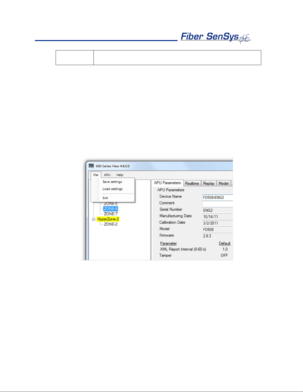
The tuning parameters can be saved for all HyperZones into a single file on a PC. This
may be useful for restoring all system settings to the APU, or transferring them to another
APU. To save and restore the settings, use the buttons in the File menu while in the APU
Parameters screen.
To save calibration settings for all HyperZones, click on the File menu, and select the
“Save settings” button. A Save As dialog box displays, requesting a file name and
location; the file extension .prm is provided automatically. Enter the file information in the
Save As dialog box and click OK. 500 Series View copies all parameters from each
HyperZone and stores them in the designated file. The values read from the APU for the
currently selected HyperZone are also displayed on the APU Parameters screen.
Figure 5-3. Filer operation buttons
To restore all APU settings, select the “Load settings” button and an Open dialog box
displays. Select the correct .prm file and click OK. 500 Series View writes all parameter
settings from the file to all HyperZones on the APU. This may take several seconds
depending on how many HyperZones are in the system. The values written from the file to
the APU for the currently selected HyperZone are also displayed on the APU Parameters
screen.
Fiber Defender FD508TM User Manual 18
Assigning a Device Name
If your APU is installed in an existing local-area network, you can assign a unique device
name to the APU that will be the name used to address the device in all XML messages.
Click on the Device Name field on the APU Parameters screen and enter the name. Click
on the Write button to write the name to the APU.
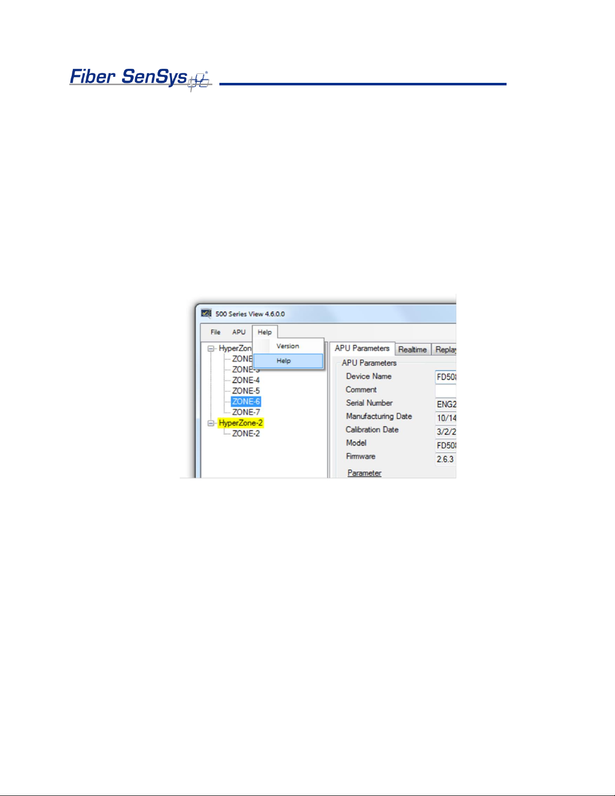
Help Menu
Help is accessed from the menu at the top of the screen.
Figure 5-4. 500 Series View main Help menu
To view help in context, right click on any field on the screen to display a pop-up Help
option and left click on the pop-up. This displays the specific help text for that field.
The Realtime Tab
As a tuning aid, 500 Series View allows for the ability to view and record live signals from
any zone. To use this function, click on the Realtime tab.
You can display real time data for any zone listed in the HyperZone tree by double clicking
on the selected zone. 500 Series View pauses momentarily while establishing contact with
the new zone, which is then highlighted. A progress bar in the lower right corner of the
screen shows the display being updated in real time.

Fiber Defender FD508TM User Manual 19
A status legend on the right-hand side of the screen shows alarms and events associated
with Processors 1 and 2. Alarm indicators are shown in red and event indicators in yellow.
Events and alarms are also shown as flashes across the Realtime window.
On the Realtime window, you can choose to view the sensor data in either Spectral mode
or Time mode. In Spectral mode the display shows the sensor data as a function of
frequency (see figure 5-5). In Time mode, the display shows sensor data as a function of
time (see figure 5-6)
Figure 5-5. The 500 Series View Realtime screen
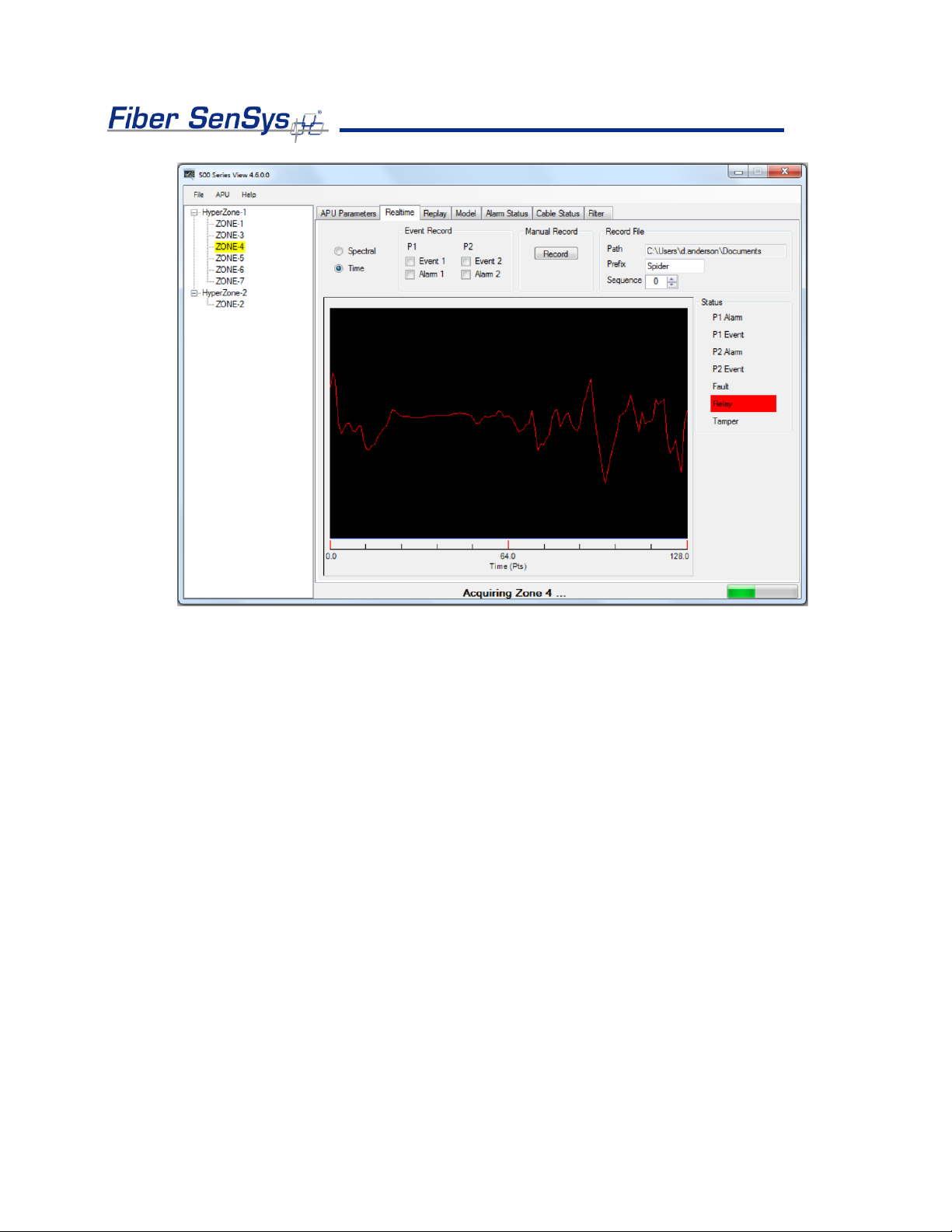
Fiber Defender FD508TM User Manual 20
Figure 5-6. Realtime mode, showing data as a function of time (each sample point equals about 0.8 msec.)
Table of contents


