AE&T A105NAPPX User manual
A105NAPPX & AL105NAPPX APPELLO
Alarm Tone andVoiceAnnunciation Sounder
1)Introduction
TheAppellotoneandspeechannunciation
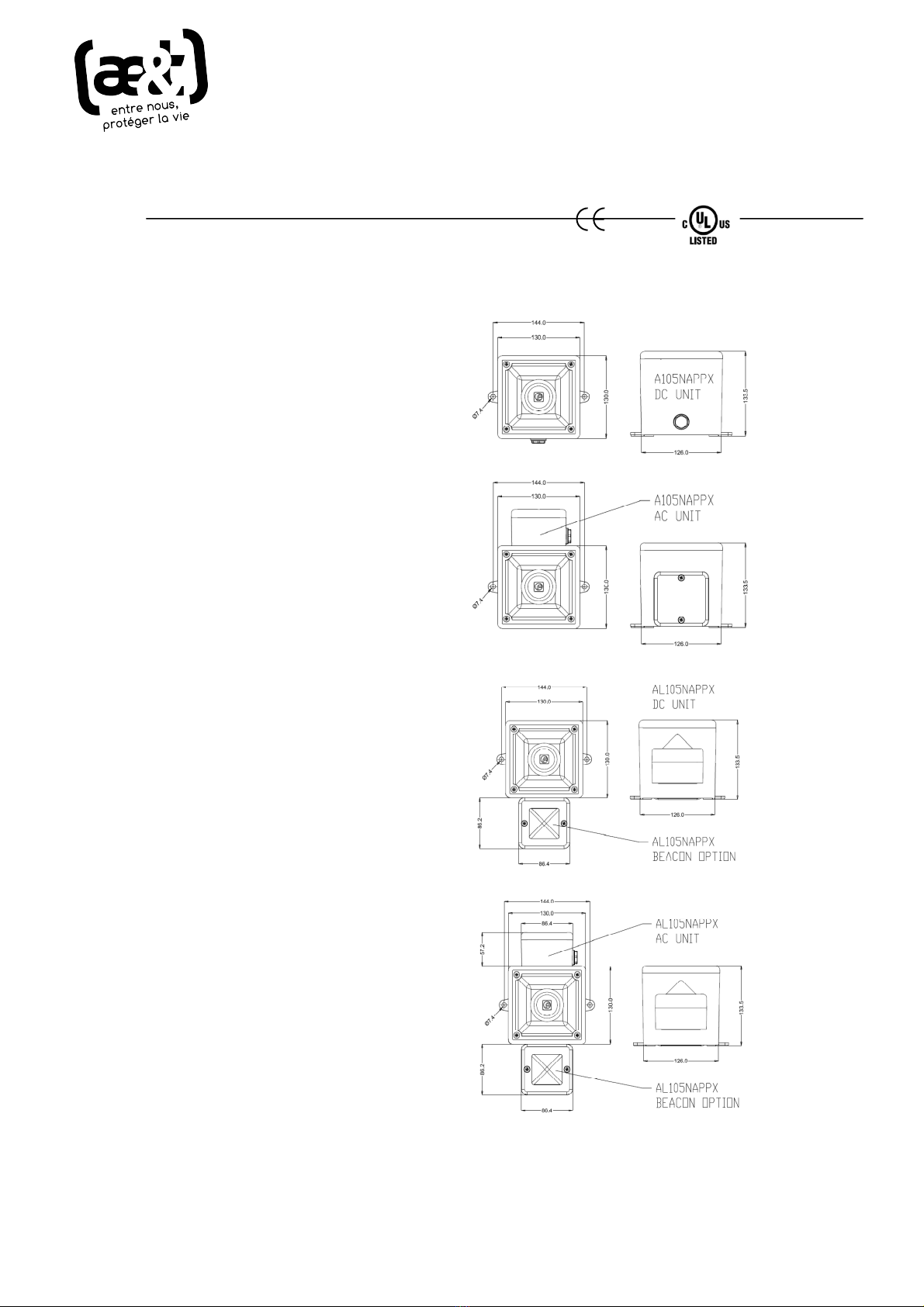
sounderhasthree different stylesin AC andDC.
•A105NAPPXSounder
•AL105NAPP Sounder-BeaconCombination
Sounder-BeaconCombination unitsare
availableas eitherahighoutputLED or
Xenonstrobe.
TheseSounder unitsshareacommonset of
functions:-
•4 stages,eachstage canrecord upto 30
secondsof CDqualityaudio.
•Facilitytorecord viaanonboard microphone
or a line in input.
•The recordedmessage can beplayed back
proceededeither with orwithoutthe choice
of one of fortyfive tones.
The Beacon functionsareeither:-
•XenonStrobe-1Hzflash rate
•LED - Either Steadyor 2Hzblinkrate
2)Operating and Marking
All unitshave the following operating
requirementsand limitations.
Unit TypeNo. VoltageRangeCurrent
Sounder only outputs
A105NAPPXDC 24Vdc10-30Vdc256mA
MaxCurrent256mA @ 30Vdc
A105NAPPXAC 115Vac90-260Vac112mA
230Vac90-260Vac124mA
MaxCurrent127mA @ 260Vac
AL105NAPPXcombined unit - Add selected
sounder& beaconcurrentsto calculate total
currentrequired.
Beacon onlyoutputs
LEDBeacon DC24Vdc10-30Vdc157mA
MaxCurrent166mA @ 30Vdc
LEDBeacon AC115Vac90-260Vac60mA
230Vac90-260Vac35mA
MaxCurrent60mA @ 90Vac
Xenon Beacon DC 12Vdc 10-14Vdc500mA
24Vdc20-28Vdc250mA
Xenon Beacon AC 115Vac+/-10%Vac100mA
230Vac+/-10%Vac50mA
Operating Temp: -20 to +55°C
IP Rating: Type4/4X/3R /13, IP66
Marking:
3)Installation & WiringRequirements
A105NAPPX
AL105NAPPX
INSTRUCTION MANUAL
ϭϬϱEyͲĨĂĐƚŽƌLJƌĞĨ
W>KϱͲĐŽŵŵĞƌĐŝĂůƌĞĨ
ae&t - 4 impasse Joliot Curie - 64110 Jurançon - tél 05 59 06 06 00 - [email protected] - aet.fr
Alwaysde-energize unit before removing cover.
Theinstallationof the unitsmustbein
accordancewithanylocal codesthat mayapply
and shouldonlybecarriedout byacompetent
trainedelectrical engineer.
Thepowerterminalson thecontrol unit are
clearlymarkedandwill acceptupto 1.5mm2
cable.
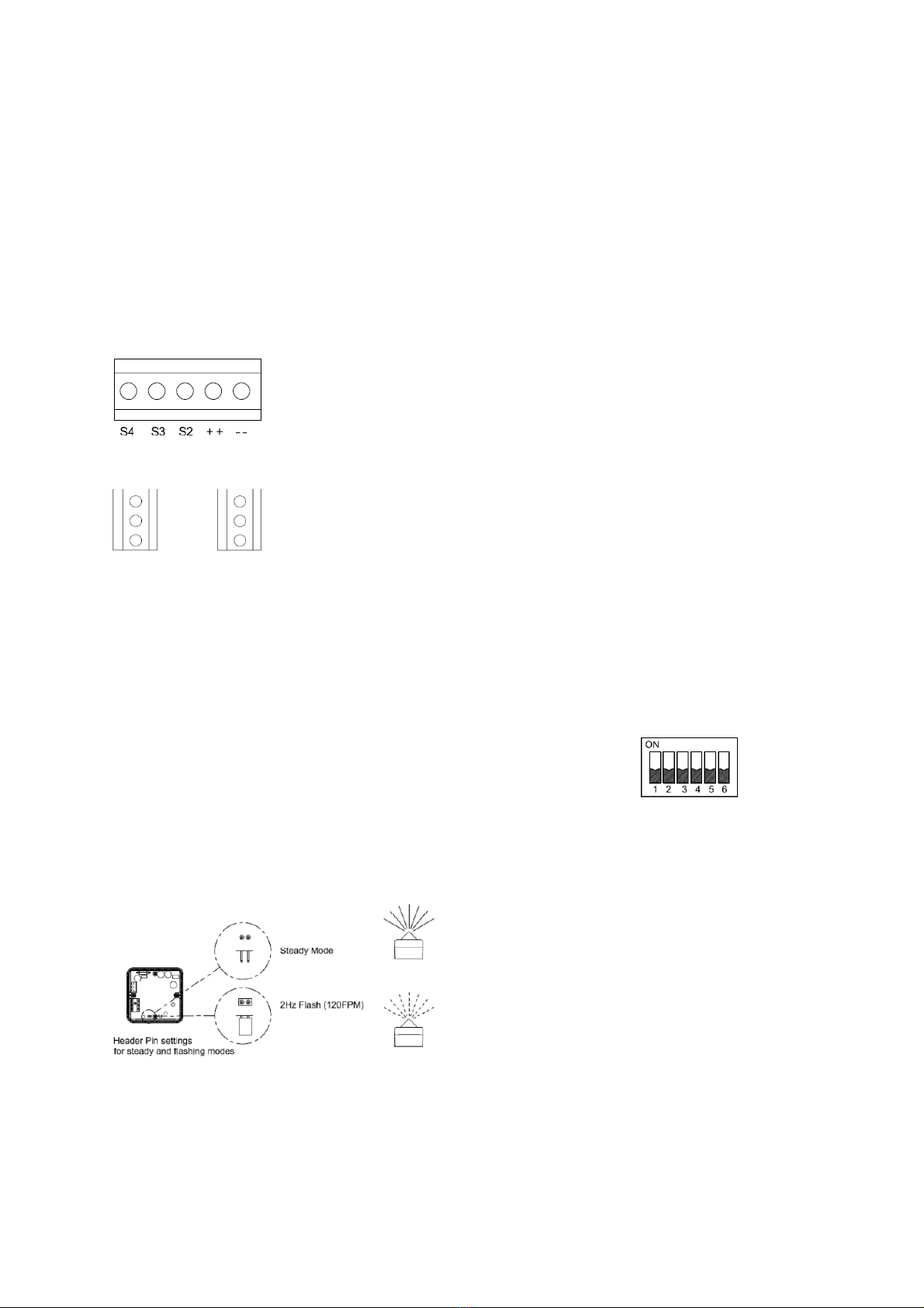
DCTerminals
OnmainPCB.
++ = Positive
--=Negative
ACTerminals
OnSub PCB
L= Live
N =Neutral
E=Earth
TheAL105Nunitswill havethe beacon already
prewiredto the unit so no extrawiring isrequired.
4)BeaconSet-up
The beaconunitmayneedto beconfigured
dependanton the type of flashrequired.
The xenon beacon hasa1Hzflash rate only.
The LED beaconisset as standard tothe2Hz
flash modebutit can beset to a steady on mode
also. To alter the settings,change the position of
theheader pin asshown.
•Removeheader for steadymode.
•Keepheader in standardposition for
2Hzflashingmode
5)UnitSet-up and Recording
The unit will needto be configured to suit theend
user.
Ifrecording eithervia the onboardmicrophoneor
thein-line connectortheunitwill need tobe
supplied with power.
DC unitscanbe poweredwhencompleting
recording and set-up.
Warning!: During set-up AC units must be
temporarilypoweredfromeithera12V battery
or aseparate 10-30VDC isolated powersupply,
connected directlytothe DC terminals on the
main appello PCB. This is because the AC
units power supplyisnotisolated and there
maybeariskofelectric shock.
See section 7) AppelloSetupGuide overleaf for
Set-up instructionsandfunctions.
6)ToneSelectionTable
The Appellounithas45different tones(See
Table 1)thatcan beselected for the firststage
alarm. Thesystemscanthenbeswitched to
sound second, thirdand fourth stagealarmtones.
The tonesare selectedbyoperation ofaDIP
switch S4on themain PCB.
The tonetable (Table1)shows the switch
positionsfor the45 tonesandwhichtonesare
available for the second third andfourth stages.
Example
S4Dip Switch -
ShownSetfor Tone1
(AllswitchesOFF)
To soundstageonesimplyconnectthesupply
voltage(+veand –ve)for DCunitsand(L,N, E)
forAC units,tothesupply input terminalsonthe
correctPCBshown.
L
N
E
S2
S3
S4
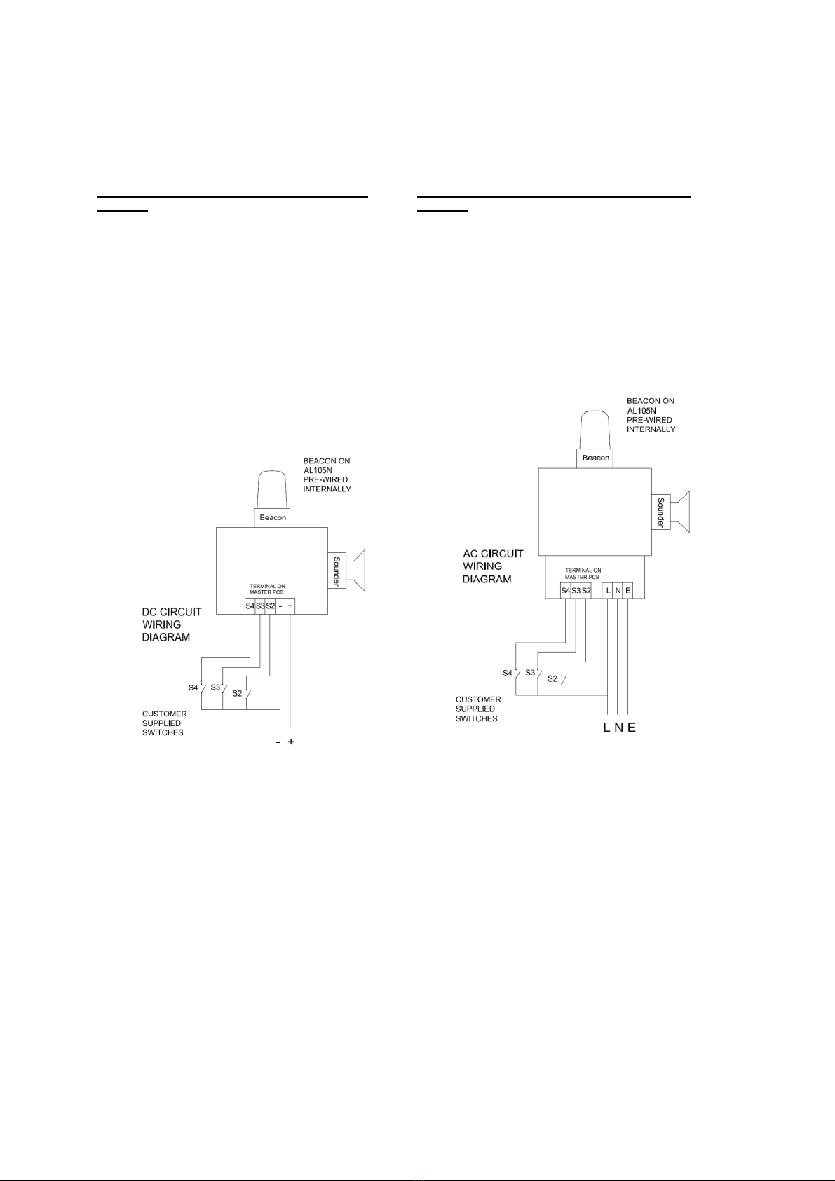
DCUnitsSecond, Thirdand Fourth Stage
Selection
TheAppellounituses–veswitchingto change
thetoneto the second, third and fourthstages.
Warning!:Thenegativesupplymustremain
connected to the-(ve) terminaland alink
madefromthis to the appropriatestage (S2)
terminalotherwise the unit willbedamaged.
Tochange tothesecond, thirdorfourth stage
tone, linkthe -vesupplyline toterminal relevant
stage terminal.Ie. forStage 2linkthe-vesupply
to theS2 terminal,forStage3linkthe-vesupply
to the S3 terminal etc.
ACUnitsSecond, Third andFourth Stage
Selection
The Appello unitusesLiveswitchingto change
thetone tothe second, third andfourthstages.
To change tothe second, third orfourth stage
tone, whilstmaintainingthe acsupplyto theLive
and neutral,alsolinktheLivesupplyline to
terminal relevant stageterminal. i.e. forStage2
linktheLivesupplyto theS2terminal, for Stage3
linkthe Live supplyto the S3 terminal etc.
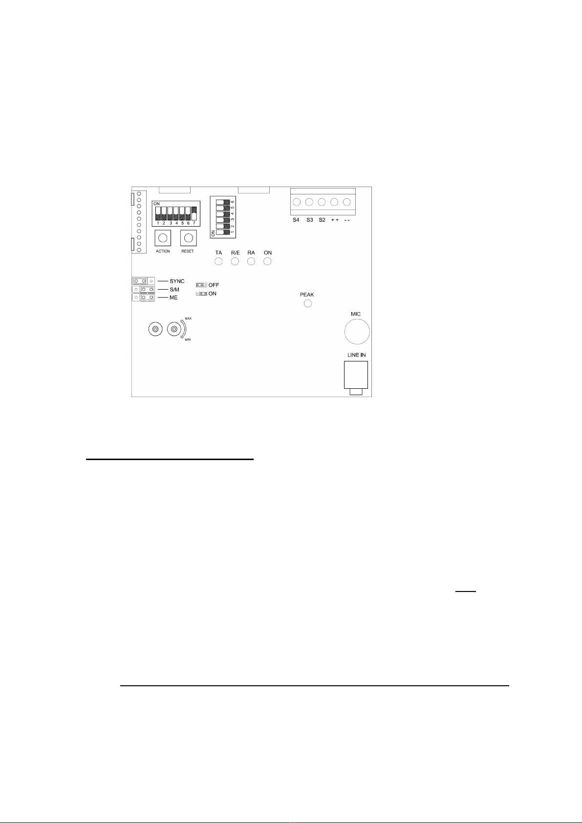
S2-Set-up S4- Tones Power& Alarm StageTerminal
Function L.E.D's
Peaklevel L.E.D
On board microphone
Audio Line-in
Jumper AlarmTone & (Voice) Recorded Content
Volume Controls
7)AppelloSetup Guide
The following guide is designed to get theuser quicklyinterfacing with the Appello unit.
•The Appello unit canbeset-up toeither playan attention seeking toneand then a recorded
messageorjust playthe recorded message.
•The user can:
oRecord on each of the 4stages using either the Line In or Microphone inputs
oSelectthe required alarmtone
oDelete unwanted messages.
•To re-record amessage on a particularstage,the previous messageon that stage must be
deleted first.
•Once theuser has configuredthe unit,it must be put intoit'sPlayback Mode and S2switchesset
to stage 1,asshown in Quick Ref - Playback Mode (Stage 1 illustrated) guidebelow.
•The “Mass Erase”function will erase alltherecorded stages.
•The "MassErase"can also be used toresettheunitifany functionality islost.
Quick ref - Switch ‘S2’ Dip SwitchFunction Settings
Switch
No. OFF Position
Function ON Position Function
1 Record Mode PlaybackMode
2
Stage selectionswitch Switch 2 On & Switch3On = AlarmStage1
Switch 2 Off& Switch3On = AlarmStage2
Switch 2 On & Switch3Off = AlarmStage3
Switch 2 Off& Switch3Off = AlarmStage4
3 Stage selectionswitch
4 Line-In selectedOn board Microphone selected
5 Program – Record &
Erase ModeON Playback–Record& EraseMode OFF
6 Message & Tone
Playback MessageonlyPlayback
7 Single Message or
MassErase ModeOFF Single Messageor MassErase Mode ON
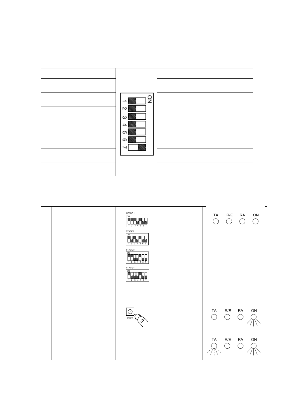
Quick Ref - PlaybackMode(Stage 1 illustrated)
1
ForStage1:
Set Switch ‘S2’positions
1,2,3 & 5 to 'ON'
Alternativelyfor :
ForStage2:
Set Switch ‘S2’positions
1,3 & 5to 'ON’
ForStage3:
Set Switch ‘S2’positions
1,2 & 5to 'ON'
ForStage4:
Set Switch ‘S2’positions
1 & 5to 'ON'
2 Switchonpower or
Press resetbutton
3a Unitwill soundalarm tone
andthen recorded
content repeatedly

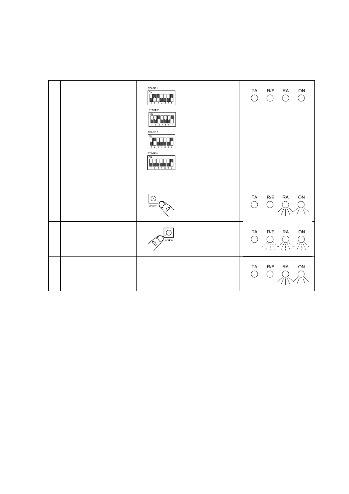
Quick Ref - Recording Mode(Stage 1 illustrated)
1
ForStage1:
Set Switch ‘S2’positions
2,3 & 4to 'ON'
Alternativelyfor :
ForStage2:
Set Switch ‘S2’positions3
&4to 'ON'
ForStage3:
Set Switch ‘S2’positions2
&4to 'ON'
ForStage4:
Set Switch ‘S2’position 4 to
'ON'
To record from Line-in
instead of the on board
microphonefollowabove
step1but set Switch ‘S2’
position 4 toOFF
2 Switchonpower or
Press resetbutton
3a Press action button:
Start recording
3b
Speakinto microphone or
plugline-in.
Itissuggestedthat a 5cm
gapismaintainedto the
microphone.
ThepeakdetectorL.E.D
shouldflashregularlyto
maintaina good recording
level.
However,if itstays on for
mostof the time, the
recordingmaybe distorted.
4 Press action button:
Stop recording
Quick Ref - EraseSinglestageMode(Stage 1 illustrated)
1
ForStage1:
Set Switch ‘S2’positions
2,3 & 7to 'ON'
Alternativelyfor :
ForStage2:
Set Switch ‘S2’positions
3 & 7to 'ON'
ForStage3:
Set Switch ‘S2’positions
2 & 7to 'ON'
ForStage4:
Set Switch ‘S2’position 7
to 'ON'
2 Switchonpower or
Press resetbutton
3a Press action button:
Erase will begin
3b - - - - erase complete
Quick Ref - MassEraseMode (Erases All Stages)
1 Set Switch ‘S2’position
7 to 'ON'
2
Set jumper J4
‘ME’ to ON position
(centreand rightpin
connected)
3 Switchonpower or
Press resetbutton
4a Press action button:
Erase will begin
4b - - - - erase complete
5 ResetJumperJ4
‘ME’ to OFF position

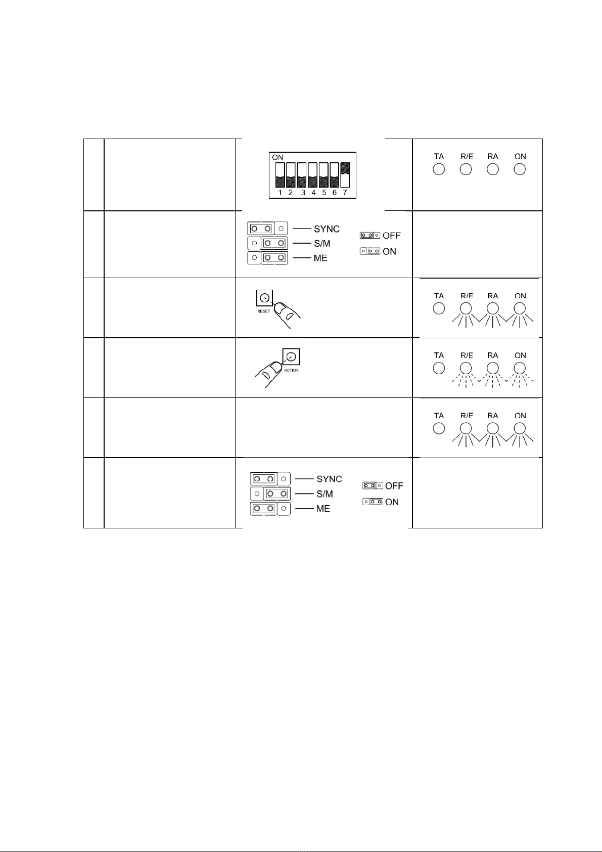
Quick Ref - Synchronising TwoSounders (All stages)
1 ConnectSynch cable to
Master andSlave PCB
2
Set 1off UnitsasMaster
and1off Unit asSlave
Set jumper J6 to Syncon
Set jumper J5 S/M on
Master unit to master
position (on)
Set jumper J5 S/M on
Slaveunit toslave
position (off)
PositionofS2 switch
doesnotaffect synch
operation.
3
Switchonpower onto the
Master unit first
Then switch power onto
the Slaveunit
MasterUnit
Slave Unit
4a Press action button on the
Master Unit:
Synchronisation will begin
MasterUnit
Slave Unit
4b
- - - - Synchronisation
complete
SwitchoffPowerto units
MasterUnit
Slave Unit
5
Reseton bothunits
jumper J6toSyncoff
Set jumper J5 S/M on
both unitstoMaster
position (on)

Table 1:Tone selection table
Stage1
Tone 1
Tone 2
Tone 3
Tone 4
Tone 5
Tone 6
Tone 7
Tone 8
Tone 9
Tone 10
Tone 11
Tone 12
Tone 13
Tone 14
Tone 15
Tone 16
Tone 17
Tone 18
Tone 19
Tone 20
Tone 21
Tone 22
Tone 23
Tone 24
Tone 25
Tone 26
Tone 27
Tone 28
Tone 29
Tone 30
Tone 31
Tone 32
Tone 33
Tone 34
Tone 35
Tone 36
Tone 37
Tone 38
Tone 39
Tone 40
Tone 41
Tone 42
Tone 43
Tone 44
Tone 45
Table 1: Tone selectiontable
Stage1
FrequencyDescription
Tone 1
340 Hz Continuous
Tone 2
800/1000Hz@0.25secAlternating
Tone 3
500/1200Hz@0.3Hz0.5sec SlowWhoop
Tone 4
80
0/1000Hz@1Hz Sweeping
Tone 5
24
00Hz Continuous
Tone 6
2400/2900Hz @7HzSweeping
Tone 7
2400/2900Hz @1HzSweeping
Tone 8
500/1200/500Hz @0.3Hz Sweeping
Tone 9
1200/500Hz@1Hz
Tone 10
2400/2900Hz @2HzAlternating
Tone 11
1000Hz @1HzIntermittent
Tone 12
800/1000Hz@0.875Hz
Tone 13
2400Hz @1HzIntermittent
Tone 14
800Hz 0.25secon,1secoff Intermittent
Tone 15
800Hz Continuous
Tone 16
660Hz 150mSon, 150mSoff Intermittent
Tone 17
544Hz (100mS)/440Hz (400mS)
Tone 18
660Hz 1.8secon,1.8secoffIntermittent
Tone 19
1.4KHz
Tone 20
660Hz Continuous
Tone 21
554Hz/440Hz @1Hz Alternating
Tone 22
544Hz @0.875sec. Intermittent
Tone 23
800Hz @2HzIntermittent
Tone 24
800/1000Hz@50HzSweeping
Tone 25
2400/2900Hz @50Hz Sweeping
Tone 26
Bell
Tone 27
554Hz Continuous
Tone 28
440Hz Continuous
Tone 29
800/1000Hz@7Hz Sweeping
Tone 30
300Hz Continuous
Tone 31
660/1200Hz@1Hz Sweeping
Tone 32
Twotonechime.
Tone 33
745Hz @1HzIntermittent
Tone 34
1000&2000Hz @ 0.5sec
Tone 35
420Hz @0.625secAustralianAlert
Tone 36
500-
1200Hz 3.75sec /0.25sec. AustralianEvac.
Tone 37
1000Hz Continuous
Tone 38
2000Hz Continuous
Tone 39
800Hz 0.25secon,1secoff Intermittent
Tone 40
544Hz (100mS)/440Hz (400mS)
Tone 41
MotorSiren
Tone 42
MotorSiren
Tone 43
1200Hz Continuous
Tone 44
Motor
Tone 45
1KHz1son,1s off Intermittent
Table1:Tone selection table
FrequencyDescription
340Hz Continuous
800/1000Hz@0.25sec Alternating
500/1200Hz@0.3Hz0.5secSlowWhoop
0/1000Hz@1Hz Sweeping
00Hz Continuous
2400/2900Hz @7Hz Sweeping
2400/2900Hz @1Hz Sweeping
500/1200/500Hz@ 0.3Hz Sweeping
1200/500Hz@1Hz
-
2400/2900Hz @2Hz Alternating
1000Hz @1Hz Intermittent
800/1000Hz@0.875Hz
2400Hz @1Hz Intermittent
800Hz 0.25sec on,1sec off Intermittent
800Hz Continuous
660Hz 150mSon,150mSoff Intermittent
544Hz (100mS)/440Hz(400mS)
660Hz 1.8secon, 1.8sec offIntermittent
1.4KHz
-
1.6KHz 1s,1.6KHz
660Hz Continuous
554Hz/440Hz @1Hz Alternating
544Hz @0.875sec. Intermittent
800Hz @2Hz Intermittent
800/1000Hz@50Hz Sweeping
2400/2900Hz @50HzSweeping
554Hz Continuous
440Hz Continuous
800/1000Hz@7Hz Sweeping
300Hz Continuous
660/1200Hz@1Hz Sweeping
Twotonechime.
745Hz @1Hz Intermittent
1000&2000Hz@0.5sec
420Hz @0.625sec AustralianAlert
1200Hz 3.75sec/0.25sec.Australian Evac.
1000Hz Continuous
2000Hz Continuous
800Hz 0.25sec on,1sec off Intermittent
544Hz (100mS)/440Hz(400mS)
MotorSiren
-
slowriseto1200 Hz
MotorSiren
-
slowriseto800Hz
1200Hz Continuous
Motor
Siren -
slowriseto2400 Hz
1KHz 1son, 1soff Intermittent
Table 1: Tone selectiontable
FrequencyDescription
800/1000Hz @ 0.25secAlternating
500/1200Hz @ 0.3Hz 0.5sec SlowWhoop
0/1000Hz@1Hz Sweeping
2400/2900Hz @7Hz Sweeping
2400/2900Hz @1Hz Sweeping
500/1200/500Hz @0.3Hz Sweeping
-
DIN/ PFEERP.T.A.P.
2400/2900Hz @2Hz Alternating
1000Hz @1Hz Intermittent
800/1000Hz @ 0.875Hz
Alternating
2400Hz @1Hz Intermittent
800Hz 0.25secon,1secoff Intermittent
660Hz 150mSon, 150mSoff Intermittent
544Hz (100mS)/440Hz (400mS)
-
NF S32
660Hz 1.8secon, 1.8secoffIntermittent
1.6KHz 1s, 1.6KHz
-
1.4KHz 0.5s
554Hz/440Hz @1HzAlternating
544Hz @0.875sec. Intermittent
800Hz @2HzIntermittent
800/1000Hz @ 50Hz Sweeping
2400/2900Hz @50Hz Sweeping
800/1000Hz @ 7Hz Sweeping
660/1200Hz @ 1Hz Sweeping
745Hz @1HzIntermittent
1000 &2000Hz@ 0.5sec
Alternating
420Hz @0.625sec AustralianAlert
1200Hz 3.75sec /0.25sec. AustralianEvac.
1000Hz Continuous
-
PFEERToxicGas
800Hz 0.25secon,1secoff Intermittent
544Hz (100mS)/440Hz (400mS)
-
NF S32
slowriseto1200Hz
slowriseto800Hz
1200 Hz Continuous
slowriseto2400Hz
1KHz1s on,1soff Intermittent
-
PFEERGen.Alarm
Table1: Toneselection table
800/1000Hz@0.25secAlternating
500/1200Hz@0.3Hz0.5secSlow Whoop
500/1200/500Hz@0.3HzSweeping
DIN / PFEER P.T.A.P.
Alternating
800Hz0.25secon,1 secoff Intermittent
660Hz150mS on, 150mS off Intermittent
NF S 32
-001
660Hz1.8secon, 1.8secoffIntermittent
1.4KHz0.5s
-NFC48-
265
Alternating
-
Singapore
420Hz@0.625 secAustralianAlert
1200Hz3.75sec/0.25sec.AustralianEvac.
PFEER ToxicGas
800Hz0.25secon,1 secoff Intermittent
NF S 32
-001
PFEER Gen.Alarm
Table 1:Tone selection table
265
Singapore
PFEER Gen. Alarm
Switch
1 2
Switch
3 4 5
Stage2
6 (S2)
Tone 2
Tone 17
Tone 2
Tone 6
Tone 3
Tone 7
Tone 10
Tone 2
Tone 15
Tone 7
Tone 2
Tone 4
Tone 15
Tone 4
Tone 2
Tone 18
Tone 2
Tone 2
Tone 2
Tone 2
Tone 2
Tone 2
Tone 6
Tone 29
Tone 29
Tone 2
Tone 26
Tone 2
Tone 7
Tone 2
Tone 26
Tone 26
Tone 2
Tone 38
Tone 36
Tone 35
Tone 9
Tone 34
Tone 23
Tone 31
Tone 2
Tone 2
Tone 2
Tone 2
Tone 38
Stage2
Stage3
(S3)
Tone 5
Tone17
Tone 5
Tone 5
Tone 5
Tone 20
Tone 5
Tone10
Tone 5
Tone 5
Tone15
Tone 2
Tone 5
Tone 5
Tone 5
Tone15
Tone 5
Tone 5
Tone 5
Tone18
Tone 5
Tone 27
Tone 5
Tone 5
Tone 5
Tone 5
Tone 5
Tone 5
Tone29
Tone 5
Tone29
Tone 5
Tone 15
Tone26
Tone 5
Tone 5
Tone 5
Tone 5
Tone26
Tone 5
Tone26
Tone 15
Tone 5
Tone38
Tone 45
Tone36
Tone 5
Tone35
Tone 5
Tone 45
Tone34
Tone 45
Tone23
Tone 17
Tone31
Tone 27
Tone 5
Tone 5
Tone 5
Tone 5
Tone38
Tone 34
Stage4
(S4)
Tone 29
Tone 29
Tone 29
Tone 29
Tone 29
Tone 29
Tone 29
Tone 29
Tone 29
Tone 29
Tone 29
Tone 29
Tone 29
Tone 29
Tone 29
Tone 29
Tone 29
Tone 29
Tone 29
Tone 29
Tone 29
Tone 29
Tone 29
Tone 29
Tone 29
Tone 29
Tone 29
Tone 29
Tone 29
Tone 29
Tone 29
Tone 29
Tone 29
Tone 29
Tone 29
Tone 29
Tone 29
Tone 29
Tone 29
Tone 29
Tone 29
Tone 29
Tone 29
Tone 29
Tone 29
This manual suits for next models
2
Other AE&T Marine Equipment manuals


