Edgetech 8242XS User manual


ii
8242XS Release 0004815_REV_G
The information, figures, and specifications in this manual are proprietary and are issued in strict
confidence on condition that they not be copied, reprinted, or disclosed to a third party, either wholly or
in part, without the prior, written consent of EdgeTech. Any reproduction of EdgeTech supplied software
or file sharing is strictly prohibited.
Copyright © 2011 – 2018 EdgeTech. All rights reserved.

iii
ATTENTION – READ THIS FIRST!
All personnel involved with the installation, operation, or maintenance of the equipment described in this
manual should read and understand the warnings and cautions provided below.
CAUTION!
This equipment contains devices that are extremely sensitive to static
electricity. Therefore, extreme care should be taken when handling them.
Normal handling precautions involve the use of anti-static protection
materials and grounding straps for personnel.
WARNING!
High Voltage may be present in all parts of the system. Therefore, use
caution when the electronics are removed from their containers for
servicing.
Warnings, Cautions, and Notes
Where applicable, warnings, cautions, and notes are provided in this manual as follows:
WARNING!
Identifies a potential hazard that could cause injury or death.
CAUTION!
Identifies a potential hazard that could damage equipment or data.
NOTE: Recommendations or general information that is particular to the
material being presented.

iv
8242XS Release 0004815_REV_G
HARDWARE VARIATIONS AND COMPATIBILITY
The 8242XS Release contains both standard and proprietary hardware. At times, EdgeTech may change
the standard components due to their availability or performance improvements. Although the
component manufacturers—along with their models and styles—may change from unit to unit,
replacement parts will generally be interchangeable.
EdgeTech will make every effort to see that replacement components are interchangeable and use the
same software drivers (if applicable). At times, however, direct replacements may not exist. When this
happens, EdgeTech will provide the necessary drivers with the replacement part, if applicable.
EdgeTech may also change certain hardware per customer requirements. Therefore, portions of this
manual, such as parts lists and test features, are subject to change. These sections should be used for
reference only. When changes are made that affect system operation, they will be explicitly noted. Also,
some options and features may not be active in the customer’s unit at time of delivery. Upgrades will be
made available when these features are implemented.
Contact EDGETECH CUSTOMER SERVICE with any questions relating to compatibility.

v
ABOUT THIS DOCUMENT
We, the employees at EdgeTech, would like to thank you for purchasing the 8242XS Release. At EdgeTech,
it is our policy to provide high-quality, cost-effective products and support services that meet or exceed
your requirements. We also strive to deliver them on-time, and to continuously look for ways to improve
them. We take pride in the products we manufacture, and want you to be entirely satisfied with your
equipment.
Purpose of this Manual
The purpose of this manual is to provide the user with information on the setup and use of EdgeTech’s
8242XS Release. Although this manual encompasses the latest operational features of the 8242XS, some
features may be periodically upgraded. Therefore, the information in this manual is subject to change and
should be used for reference only.
Liability
EdgeTech has made every effort to document the 8242XS Release in this manual accurately and
completely. However, EdgeTech assumes no liability for errors or for any damages that result from the
use of this manual or the equipment it documents. EdgeTech reserves the right to upgrade features of
this equipment, and to make changes to this manual, without notice at any time.
Revision History
REVISION
DESCRIPTION
DATE
APPROVAL
A
Release to Production
01/02/2011
RM
B
Updates
N/A
RM
C
Updates
N/A
RM
D
Corrected to Historical Rev
10/05/2012
RM
E
Change Release Load Spec
10/05/2012
RM
F
Update Format & Pictures
11/10/2014
RM
G
Updates to Content, Drawings,
03/30/18
RM

vi
8242XS Release 0004815_REV_G
WARRANTY STATEMENT
All equipment manufactured by EdgeTech is warranted against defective components and workmanship
for a period of one year after shipment. Warranty repair will be done by EdgeTech free of charge.
Shipping costs are to be borne by the customer. Malfunction due to improper use is not covered in the
warranty, and EdgeTech disclaims any liability for consequential damage resulting from defects in the
performance of the equipment. No product is warranted as being fit for a particular purpose, and there is
no warranty of merchantability. This warranty applies only if:
i. The items are used solely under the operating conditions and in the manner recommended in
Seller's instruction manual, specifications, or other literature.
ii. The items have not been misused or abused in any manner, nor have repairs been attempted
thereon without the approval of EdgeTech Customer Service.
iii. Written notice of the failure within the warranty period is forwarded to Seller and the directions
received for properly identifying items returned under warranty are followed.
iv. The return notice authorizes Seller to examine and disassemble returned products to the extent
Seller deems necessary to ascertain the cause for failure.
The warranties expressed herein are exclusive. There are no other warranties, either expressed or implied,
beyond those set forth herein, and Seller does not assume any other obligation or liability in connection
with the sale or use of said products. Any product or service repaired under this warranty shall be
warranted for the remaining portion of the original warranty period only.
Equipment not manufactured by EdgeTech is supported only to the extent of the original manufacturer's
warranties.

vii
RETURNED MATERIAL AUTHORIZATION
Prior to returning any equipment to EdgeTech, a Returned Material Authorization (RMA) number must be
obtained. The RMA will help identify returned equipment when it arrives at our receiving dock and enables
tracking of the equipment while at our facility. The material should be shipped to EdgeTech, 4 Little Brook
Road, West Wareham, MA 02576. Refer to the RMA number on all documents and correspondences.
All returned materials must be shipped prepaid. Freight collect shipments will not be accepted. EdgeTech
will pay freight charges on materials going back to the customer after they have been evaluated and/or
repaired. If the equipment is the property of EdgeTech, please insure for full value.
All shipments must be accompanied by three copies of your proforma invoice, with the value of the
material, and the reason for return. If the reason is for repair, it must be clearly stated in order to move
through customs quickly and without duties being charged. Whenever possible, please send copies of
original export shipping documents with the consignment. Fax one invoice, packing list, and a copy of the
airway bill to EdgeTech upon shipment to EdgeTech’s Main Office Fax: 1-508-291-2491.
If there is more than one item per consignment, a packing list must accompany the shipment, which can
be combined with the proforma invoice and packing list if the contents of each carton are clearly
numbered and identified on the invoice.
CAUTION!
If your product is a portable topside, never attempt to ship it in its Storm
CaseTM alone. Although rugged, these cases are not intended to be used
as shipping containers, and the delicate internal components could be
damaged if used in this manner.
Note: All shipping charges shall be the responsibility of the customer, and
the return shipment will be sent on the customer’s account.
Foreign and Domestic Shipping Return Instructions
1. The items must be sent prepaid to our door – using a reputable company. Freight collect
shipments will not be accepted. Small items can be shipped prepaid directly to EdgeTech via
FedEx, DHL, UPS, Airborne, etc.
2. For your protection, the items should be fully insured. EdgeTech will not assume any responsibility
for damage to the shipment while in transit inbound or outbound.
3. Items within the warranty period must be sent prepaid to our door – using a reputable company.
EdgeTech will only pay for return shipping charges, if damage was not caused by misuse.

viii
8242XS Release 0004815_REV_G
International Shipping Return Instructions
The following steps only apply to material being returned from outside the Continental United States, and
must be followed carefully to prevent delays and additional costs:
1. The waybill and all shipment documentation associated with the shipment must clearly state that
the Country of Origin/Manufacturer is USA.
2. The waybill and all associated shipment documents must state the following to eliminate
taxes levied: United States goods returned to manufacturer for repair purposes only.
3. The waybill and all documents associated with the shipment must state the following for
description (HS Tariff Code eliminates duty charges): Geophysical Scientific Instrumentation; Side
Scan System, Beacons; HS Tariff Code: 9015.80.80.80
4. If using a freight forwarder, ensure they understand that the goods are duty & tax free United
States goods returned to manufacturer for repair only. Additionally, please instruct the freight
forwarder that the shipment is FREE DOMICILE and must be delivered to our door.
5. Please send all shipping documents in advance of the shipment by email to
service@edgetech.com. Providing EdgeTech with the shipping documents will enable us to
follow up with the carrier on our end.
Also include EdgeTech’s broker information below on the commercial invoice:
Attn: Brenda Richards | Terri DiOrio
TransGroup BOS INTL, 140 Eastern Ave, Chelsea MA 02150
Office: 617-889-5089 TF: 877-839-3353 Fax: 617-889-5189
brendar.bos@transgroup.com | teresad.bos@transgroup.com
NOTE: For International Shipments, If the value of the equipment is over
$1000, the following Shipper's oath must be sent with the invoice. This
oath can be typed on the invoice or on a separate letterhead:
"I, ______________________________, declare that the articles herein specified are the growth,
produce, or manufacture of the United States; that they were exported from the
United States from the port of _____________________, on or about _______________; that they
are returned without having been advanced in value or improved in condition by any
process of manufacture or any other means; and that no drawback, or allowance has
been paid or admitted hereof."
Signed ______________________________

ix
CUSTOMER SERVICE
Customer service personnel at EdgeTech are always eager to hear from users of our products. Your
feedback is welcome, and is a valuable source of information which we use to continually improve these
products. Therefore, we encourage you to contact EdgeTech Customer Service to offer any suggestions
or to request technical support:
NOTE: Please have your system Serial Number available when contacting
Customer Service.
E-mail: service@edgetech.com
Mail: 4 Little Brook Road
West Wareham, MA 02576
Telephone: (508) 291-0057
Facsimile: (508) 291-2491
24-Hour Emergency
Technical Support Line: (508) 942-8043
For more information please go to www.EdgeTech.com.

x
8242XS Release 0004815_REV_G
COMPANY BACKGROUND
EdgeTech (formerly EG&G Marine Instruments) traces its history in underwater data acquisition and
processing back to 1966. EdgeTech has designed, developed, and manufactured products, instruments,
and systems—for the acquisition of underwater data, including marine, estuarine, and coastal
applications—for over 50 years.
The company has responded to the needs of the scientific, Naval, and offshore communities by providing
equipment—such as sub-bottom profilers, side scan sonar, acoustic releases, USBL positioning systems,
and bathymetric systems—that have become standards in the industry.
EdgeTech has also consistently anticipated and responded to future needs through an active research and
development program. Current efforts are focused on the application of cutting-edge CHIRP and acoustic
technology.

xi
TABLE OF CONTENTS
ATTENTION – READ THIS FIRST! .........................................................................................................iii
Warnings, Cautions, and Notes................................................................................................................ iii
HARDWARE VARIATIONS AND COMPATIBILITY..................................................................................iv
ABOUT THIS DOCUMENT....................................................................................................................v
Purpose of this Manual............................................................................................................................. v
Liability...................................................................................................................................................... v
Revision History ........................................................................................................................................ v
WARRANTY STATEMENT ...................................................................................................................vi
RETURNED MATERIAL AUTHORIZATION ...........................................................................................vii
Foreign and Domestic Shipping Return Instructions ............................................................................... vii
International Shipping Return Instructions ............................................................................................ viii
CUSTOMER SERVICE..........................................................................................................................ix
COMPANY BACKGROUND ..................................................................................................................x
TABLE OF CONTENTS.........................................................................................................................xi
LIST OF FIGURES.............................................................................................................................. xiv
LIST OF TABLES ............................................................................................................................... xvi
1.0 OVERVIEW ................................................................................................................................1-1
Basic Functionality ........................................................................................................................1-1
2.0 SPECIFICATIONS ........................................................................................................................2-1
Mechanical & Physical Specifications ...........................................................................................2-1
Printed Circuit Board (PCB)...........................................................................................................2-1
Acoustic Specifications..................................................................................................................2-2
BACS Command Structure..........................................................................................2-2
BACS Command Coding .............................................................................................2-3
Standard Command Functions...................................................................................2-3
Environmental Specifications .......................................................................................................2-3
Battery Types ................................................................................................................................2-3
Mechanical Drawings....................................................................................................................2-3
3.0 SETUP AND INSTALLATION.........................................................................................................3-1
Acoustic.........................................................................................................................................3-1

xii
8242XS Release 0004815_REV_G
Mechanical....................................................................................................................................3-1
Status Reply ..................................................................................................................................3-1
4.0 OPERATING INSTRUCTIONS .......................................................................................................4-1
Tools.......................................................................................................................................................4-1
Turning the Unit On ......................................................................................................................4-1
Removing the Purge Port Plug ...................................................................................4-1
Removing the Lifting Support ....................................................................................4-3
Removing the Transducer End ...................................................................................4-5
Applying Power ..........................................................................................................4-6
Closing the Transducer End........................................................................................4-7
Attaching the Lifting Support .....................................................................................4-8
Replace the Purge Port Plug.....................................................................................4-12
Leak Detection and Condensation Prevention ...........................................................................4-13
Arming the Instrument ...............................................................................................................4-14
Release Function.........................................................................................................................4-18
Release Latch Inspection (following high load in-air releases): ...............................4-19
ON/OFF Option ...........................................................................................................................4-19
On/Off Instructions ..................................................................................................4-20
4.5.1.1 On Instructions.........................................................................................................4-21
4.5.1.2 Off Instructions ........................................................................................................4-22
Air Acoustic Testing.....................................................................................................................4-23
Setup ........................................................................................................................4-23
Tests .........................................................................................................................4-23
Post Deployment ........................................................................................................................4-24
5.0 MAINTENANCE..........................................................................................................................5-1
Housing and Release Preparation and Care .................................................................................5-1
To Open the 8242XS .....................................................................................................................5-2
Tools...................................................................................................................................................5-2
8242XS Disassembly...................................................................................................5-2
Remove the Clevis End Cap........................................................................................5-4
8242XS Assembly ..........................................................................................................................5-7
Clevis End Cap Assembly............................................................................................5-7
xiii
Battery Replacement ....................................................................................................................5-9
Battery Replacement Procedure..............................................................................5-10
Battery Replacement Considerations ......................................................................5-12
5.4.2.1 Battery Replacement ...............................................................................................5-13
O-Ring Considerations ................................................................................................................5-14
Additional O-Rings....................................................................................................5-14
O-Ring Service Disassembly .....................................................................................5-14
General Cleaning and Inspection ................................................................................................5-16
Inspection Particulars...............................................................................................5-16
General Inspection and Replacement Schedule ......................................................5-17
Field Service Kit ........................................................................................................5-17
Callout Assembly Drawings.........................................................................................................5-17
0002737 BOM .............................................................................................................................5-19
0002650 BOM .............................................................................................................................5-21
0002780 BOM ..........................................................................................................5-25
A.0 REMOTE RELEASE..................................................................................................................... A-1
A.1 Mechanical Drawings................................................................................................................... A-1
B.0 TANDEM RELEASE OPTION ....................................................................................................... B-1
B.1 Parts List........................................................................................................................................B-1
B.2 Mechanical Drawings....................................................................................................................B-1

xiv
8242XS Release 0004815_REV_G
LIST OF FIGURES
Figure 1-1: An 8242XS Release in the Arctic Sea ....................................................................................... 1-1
Figure 2-1: PCB Connectors .......................................................................................................................2-1
Figure 2-2: ICD 8272-XS Short – 0010816 ..................................................................................................2-4
Figure 2-3: ICD 8242XS Long –0011329 ................................................................................................... 2-5
Figure 4-1: The Purge Port Plug .................................................................................................................4-1
Figure 4-2: Remove the Purge Port Plug Retainer .....................................................................................4-2
Figure 4-3: Removing the Purge Port Plug.................................................................................................4-2
Figure 4-4: Removing the (3) Top Nut from the (3) Titanium Bolts...........................................................4-3
Figure 4-5: Using a Wrench to Pry the Cage Apart ....................................................................................4-4
Figure 4-6: Tapping the Cage Free with a Mallet.......................................................................................4-4
Figure 4-7: Removing the Transducer End Cap..........................................................................................4-5
Figure 4-8: The Removed Transducer End Cap..........................................................................................4-5
Figure 4-9: Battery Connection Location and One Method for Plugging in the Board..............................4-6
Figure 4-10: The Proper Orientation of the Battery Pin Connector and JP5 ............................................. 4-6
Figure 4-11: Apply Pressure to the Base of the Transducer End to Fully Seat it into the Housing............4-7
Figure 4-12: Cage Assembly for Transducer End Cap ................................................................................4-8
Figure 4-13: Attach One Part of the Lifting Support .................................................................................. 4-8
Figure 4-14: Applying the Second Part of the Lifting Support, Including the ½” Spreader Rods............... 4-9
Figure 4-15: Use the Mallet to Ensure the Lifting Support is Securely Attached ....................................4-10
Figure 4-16: Replace the Two Titanium bolts ..........................................................................................4-10
Figure 4-17: Using the Wrench on the top bolt, at the bottom, tighten the first nut.............................4-11
Figure 4-18: Top End Cap Completed Assembly ......................................................................................4-11
Figure 4-19: Replace the Purge Port Plug ................................................................................................4-12
Figure 4-20: The Replaced Purge Port Plug Retainer...............................................................................4-12
Figure 4-21: Clevis Rotation Drawing....................................................................................................... 4-14
Figure 4-22: The Armed 8242XS ..............................................................................................................4-15
Figure 4-23: The Release Link Captured by the Release Hook.................................................................4-16
Figure 4-24: Capture the End of The Hook onto the Latch Recess .......................................................... 4-16
Figure 4-25: Rotating the Shaft Using the Arming Wrench .....................................................................4-17
Figure 4-26: The Armed T-Shaft............................................................................................................... 4-18
Figure 4-27: The Two Possible On/Off Actuator Plug Positions...............................................................4-19

xv
Figure 4-28: On/Off Actuator Plug on the Clevis End ..............................................................................4-20
Figure 4-29: The ON and OFF Positions of the On/Off Actuator Plug......................................................4-20
Figure 4-30: Loosen the Retainer and Move It Out of the Way...............................................................4-21
Figure 4-31: Push in the On/Off Actuator................................................................................................4-21
Figure 4-32: Return Retainer and Tighten ...............................................................................................4-21
Figure 4-33: Pull the On/Off Actuator Out...............................................................................................4-22
Figure 5-1: The Plugged in Battery and Transducers Cables......................................................................5-2
Figure 5-2: The Unplugged Battery and Transducer Cables ......................................................................5-3
Figure 5-3: Removing the (2) Top Nut from the (2) Titanium Bolts...........................................................5-4
Figure 5-4: Using a Wrench to Pry the Clevis End Cap Apart..................................................................... 5-5
Figure 5-5: Tapping the other end of the clamp with a soft Mallet...........................................................5-5
Figure 5-6: The Electronics Assembly Completely Removed from the Housing........................................5-6
Figure 5-7: O-Rings in Clevis End Cap.........................................................................................................5-7
Figure 5-8: Cross Section of the Face Seal, Gland, and Back-up O-Rings................................................... 5-8
Figure 5-9: Clamping Hardware .................................................................................................................5-9
Figure 5-10: The Plugged in Battery Cable and Transducer Cable...........................................................5-11
Figure 5-11: The Battery Pack is on the Underside of the Electronics Chassis........................................5-12
Figure 5-12: Close-up view of the (4) Bracket Screws and (2) Retainer Brackets....................................5-12
Figure 5-13: The Transducer End O-Rings................................................................................................5-15
Figure 5-14: The Release End O-Rings .....................................................................................................5-15
Figure 5-15: The Purge Port Plug O-Rings................................................................................................5-15
Figure 5-16: Cross Section of the Face Seal, Gland, and Back-up O-Rings............................................... 5-16
Figure 5-17: 8242XS MART Main Sub Assembly – 0002737 ....................................................................5-18
Figure 5-18: 8242XS Release Sub Electronics Release Assembly –0002650..........................................5-20
Figure 5-19: 8242XS Acoustic Release Transducer Assembly – 0003226 ................................................5-22
Figure 5-20: 8242XS Release Mechanism Sub Assembly – Page 1 of 2 – 002780 ................................... 5-23
Figure 5-21: 8242XS Release Mechanism Sub Assembly – Page 2 of 2 – 002780 ..................................5-24
Figure A-1: 8242XS Remote Release – 0018268 ........................................................................................A-2
Figure B-1: 8242XS Tandem Kit Drawing – 0006657 .................................................................................B-2
Figure B-2: 8242XS Tandem Short – 0017034 ...........................................................................................B-3
Figure B-3: 8242XS Tandem Long –0018532............................................................................................B-4

xvi
8242XS Release 0004815_REV_G
LIST OF TABLES
Table 2-1: Mechanical & Physical Specifications .......................................................................................2-1
Table 2-2: Acoustic Specifications.............................................................................................................. 2-2
Table 2-3: BACS Command Structure Specifications .................................................................................2-2
Table 2-4: Allowed BACS Tone Pair Breakdown ........................................................................................2-3
Table 2-5: Standard Command Functions..................................................................................................2-3
Table 2-6: Environmental Specifications—Temperature...........................................................................2-3
Table 2-7: Battery Type Specifications.......................................................................................................2-3
Table 3-1: Status Reply Meanings.............................................................................................................. 3-2
Table 5-1: General Inspection and Replacement Schedule .....................................................................5-17
Table 5-2: Field Kit – 0003102..................................................................................................................5-17
Table 5-3: 0000002737 BOM ...................................................................................................................5-19
Table 5-4: 0002650 BOM .........................................................................................................................5-21
Table 5-5: 0002780 BOM .........................................................................................................................5-26
Table B-1: 8242XS Tandem Parts List – 0006657.......................................................................................B-1

1-1
1.0 OVERVIEW
This manual describes the 8242XS, a field-proven, reliable, and versatile mooring instrument, functioning
as both an Acoustic Release and Transponder. The 8242XS can also be used for specialized applications,
such as the opening/closing of underwater valves and in Emergency Recovery Systems. The 8242XS has
been designed for use as an instrument location and recovery system on oceanographic moorings and
platforms. Additionally, the precision, high-output power transponder feature makes this instrument ideal
for use in Long Baseline (LBL) Positioning and Navigation Systems. Constructed entirely of a Nickel-
Aluminum-Bronze alloy, the 8242XS is rugged and durable, even in the harshest marine environments.
The 8242XS uses a version of the EdgeTech’s field-proven, Binary Acoustic Command System (BACS) code
structure and is compatible with the 8011M and PACS EdgeTech Deck Units, shown below. The BACS
coding structure provides 12,000 possible command codes. The release has an enable/disable command
for controlling the transponder function as a standard feature. When disabled, the transponder will not
reply when interrogated. The RELEASE command causes the 8242XS to manually disconnect from its
mooring. The RELEASE command can be sent and will cause a release whether the system is enabled or
disabled. The ENABLE and DISABLE function only controls the transponder section.
Figure 1-1: An 8242XS Release in the Arctic Sea
Basic Functionality
The transponder function can be turned ON or OFF with the ENABLE and DISABLE commands, respectively.
When disabled the transponder will not reply when interrogated, which ensures the Unit will not interfere
with nearby instruments and that no battery energy will be wasted replying to spurious noise sources
during the deployment. The ENABLE and DISABLE commands has no effect on the RELEASE command.

2-1
2.0 SPECIFICATIONS
Mechanical & Physical Specifications
WARNING!
The 8242XS is not intended for overhead lifting. Exercise extreme caution
to prevent serious personal injury.
Mechanical specifications for the 8242XS Release are as follows:
SPECIFICATIONS
VALUE
Release mechanism
Spring-driven, rotary type with advantage hook
Recommended max static load rating (working)
5,500 kg (12,000 lbs) central axis loading
Depth rating (working)
6,000 meters (19,700 ft)
Length
94.6 cm (38.00 in) (standard unit)
Housing O.D.
13 cm (5.12 in)
Housing I.D.
10 cm (4.0 in)
Weight in air
36 kg (79 lbs) (standard unit)
Weight in water
28 kg (62 lbs) (standard unit)
Exposed materials
Acetal (washers, etc.)
NiAlBz (housing, end caps, and mechanism)
Buna –N (O-Rings)
Titanium
Table 2-1: Mechanical & Physical Specifications
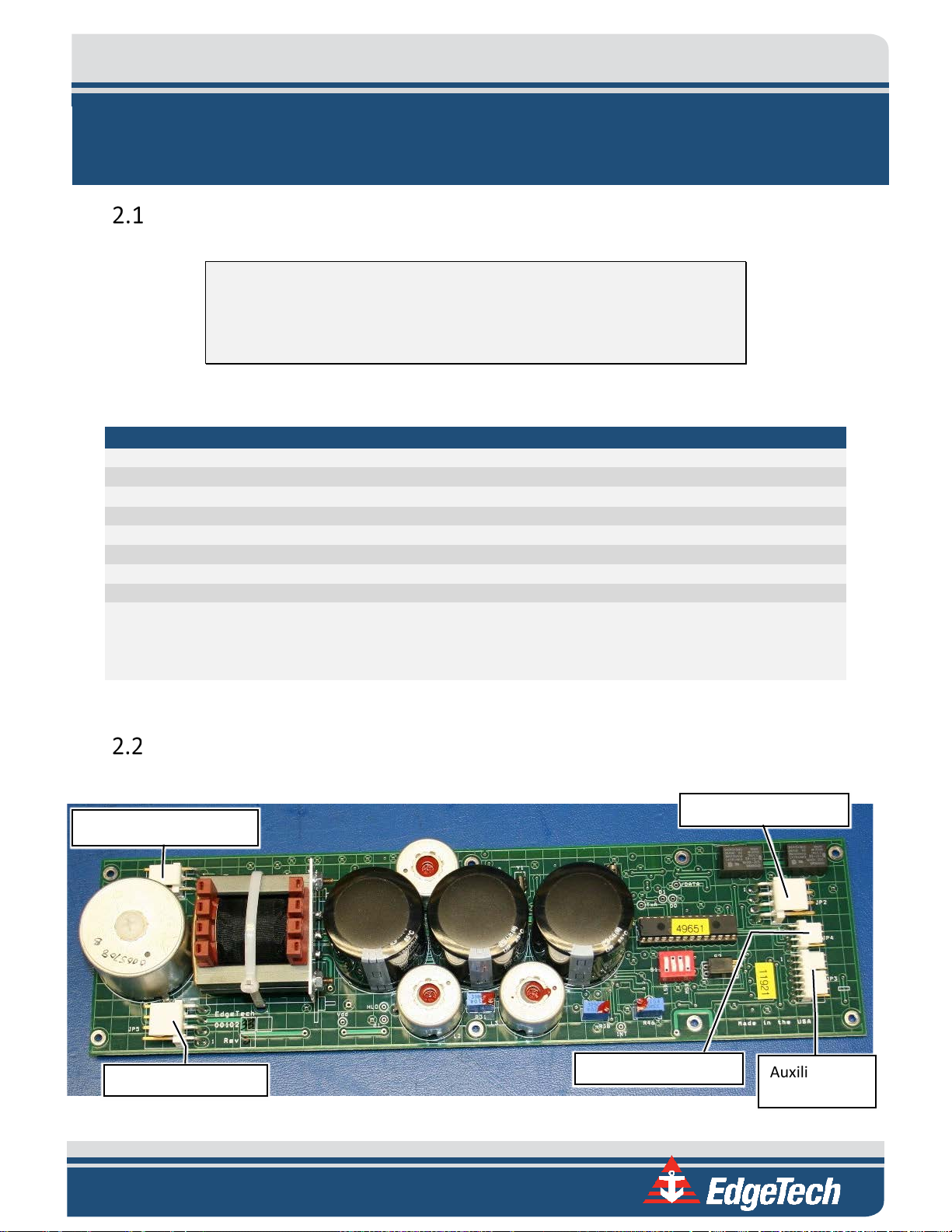
Printed Circuit Board (PCB)
The PCB connectors on the 8242XS board are shown below:
Figure 2-1: PCB Connectors
Transducer Connector
Battery Connector
Auxiliary I/O
Connector
Motor Connection
System Sense Lines

SECTION 2: SPECIFICATIONS 2-2
Acoustic Specifications
The acoustic specifications for the 8242XS unit are described in the following sub-sections.
SPECIFICATIONS
VALUE
Transmit source level
192 dB re 1 µPascal-meter
Command codes
BACS commands
Transponder sensitivity
-80 dB re 1 µPascal
Transponder SNR
> or = 44 dB re root Hz for jitter < +/- 0.5 milliseconds (3 σT).
Jitter =+/- 0.1 milliseconds for noise-free field
Interrogate frequency
11 kHz (standard unit)
Post filter bandwidth
330 Hz
Minimum interrogate pulse width
5 milliseconds
Reply frequency
Default 12 kHz
Transmit/Reply source level
192 dB re 1 µPascal-meter
Reply pulse width
10 milliseconds (standard unit)
Turnaround time delay
12.5 milliseconds (standard unit)
Lockout time
1.0 seconds
Receiver sensitivity
-100 dB re 1 µPascal-meter
Receiver SNR
> or = 36 dB re root Hz
Receiver type
Hard-limited (2000 Hz / 330 Hz bandwidths)
Table 2-2: Acoustic Specifications
BACS Command Structure
The BACS’ command structure consists of two 8-bit words separated by a 5-sec interval. Each word is
comprised of 8 bits from a 16-bit command. The 16-bit command is a 15 bit, 11 block cyclic code with an
overall parity bit appended to the end to form a 16-bit code with a minimum Hamming distance of 4 bits.
Two transitions are required within each word, and no repetitions of words are allowed in a command.
SPECIFICATION
VALUE
Coding
General to 8000 series – Binary FSK
Allowed tone pairs
Six (see TABLE 2-4) for full breakdown of pairs
Structure
Two successive 8 bit words with a 5 sec. interval between them.
Each word comprised of 8 bits from a 16 bit command. The 16 bit command is a 15,
11 block cyclic code with an overall parity bit appended to the end to form a 16, 11
code with a minimum Hamming distance of 4 bits.
Additionally, two transitions are required within each word, and no repetitions of
words are allowed in a command.
Pulse width
22 milliseconds
Period
250 milliseconds
Total command time
9 seconds
Total lockout time
14 seconds re beginning
Total command
capacity per tone pair
2,000 or 12,000 commands for six tone pairs
Standard functions
Release, Disable Transponder, Enable Transponder
Table 2-3: BACS Command Structure Specifications
Table of contents
Other Edgetech Marine Equipment manuals

Edgetech
Edgetech 3100 User manual

Edgetech
Edgetech 3400 User manual

Edgetech
Edgetech STARMUX IV User manual
Edgetech
Edgetech 4380 MULTIBEACON User manual

Edgetech
Edgetech STARMUX IV User manual

Edgetech
Edgetech 3400 User manual

Edgetech
Edgetech Model 3100P Sub-bottom Sonar System User manual

Edgetech
Edgetech 8011M User manual

Edgetech
Edgetech Port Pop-Up User manual

Edgetech
Edgetech 2050-DSS User manual


