Edgetech 4200-FS User manual

USER’S HARDWARE MANUAL
Revision: 1.2 / May, 2005
Email: [email protected]
Web: http://www.edgetech.com
4 Little brook Rd.
West Wareham, MA. 02576
Tel: (508) 291-0057
Fax: (508) 291-2492
1141 Holland Drive, Suite 1
Boca Raton, FL 33487
Tel: (561) 995-7767
Fax: (561) 995-7761
4
42
20
00
0-
-F
FS
S
High Definition, Multi-Pulse, Dual
Frequency Side Scan System


i
4
42
20
00
0-
-F
FS
S
S
Si
id
de
e
S
Sc
ca
an
n
S
So
on
na
ar
r
FORWARD
This manual is intended to provide the user with an understanding of the operation and care of
the 4200-FS side scan towfish. Although this manual covers the latest operational features of the
4200-FS, some features may be periodically upgraded. Also, certain hardware may be changed
per customer requirements. Therefore, portions of this manual such as parts lists, and test
features are subject to change. Such sections should be used for reference only. When changes
are made that affect system operation, they will be explicitly noted. Also, some options and
features may not be active in your unit at time of delivery. Upgrades will be made available
when these features are implemented.
A 4200 System consists of two hardware components plus an installed software sub-component.
The hardware components are the Model 566, or 566P, topside processor with its color video
monitor and the EdgeTech 4200-FS towfish. Information relating to the 4200-FS towfish is
included in this manual. Information relating to the Model 566 and 566P and instructions
pertaining to the installed sonar processor are included in their own individual manuals.
EdgeTech has made every effort to document this product accurately and completely. However,
EdgeTech assumes no liability for errors or for any damages that result from use of this manual
or the equipment it accompanies. EdgeTech reserves the right to upgrade features of this
equipment and to make changes to this manual without notice at any time.
Since clear and concise documentation is inherent for proper operation and understanding of the
equipment, we solicit you to contact us with any questions or comments so that we may enhance
this manual.
EdgeTech
4 Little Brook Road
West Wareham, MA 02576
Tel: (508) 291-0057
Fax: (508) 291-2491

ii
4
42
20
00
0-
-F
FS
S
S
Si
id
de
e
S
Sc
ca
an
n
S
So
on
na
ar
r
WARRANTY STATEMENT
All equipment manufactured by EdgeTech is warranted against defective components and
workmanship for repair at their plant in West Wareham, Massachusetts, free of charge, for a
period of one year. Shipping costs are to be borne by the customer. Malfunction due to improper
use is not covered in this warranty and EdgeTech disclaims any liability for consequential
damage resulting from defects in the performance of the equipment. No product is warranted as
being fit for a particular purpose and there is no warranty of merchantability. This warranty
applies only if:
(i) the items are used solely under the operating conditions and in the
manner recommended in the instruction manual, specifications, or
other literature;
(ii) the items have not been misused or abused in any manner or repairs
attempted thereon;
(iii) written notice of the failure within the warranty period is forwarded
to EdgeTech and the directions received for properly identifying
items returned under warranty are followed;
and (iv) the return notice authorizes EdgeTech to examine and disassemble
returned products to the extent EdgeTech deems necessary to
ascertain the cause for failure.
The warranties expressed herein are exclusive. There are no other warranties, either expressed or
implied, beyond those set forth herein, and EdgeTech does not assume any other obligation or
liability in connection with the sale or use of said products.
Equipment not manufactured by EdgeTech is supported only to the extent of the original
manufacturer's warranty.

iii
4
42
20
00
0-
-F
FS
S
S
Si
id
de
e
S
Sc
ca
an
n
S
So
on
na
ar
r
WARNING
THIS EQUIPMENT CONTAINS STATIC SENSITIVE DEVICES
These devices are extremely sensitive to static electrical charges which may be developed on the
body and clothing. Extreme care should be taken when handling these devices both in and out of
the circuit board. Normal handling precautions involve the use of anti-static protection materials
and grounding straps for personnel.
WARNING
This equipment generates, uses, and can radiate radio frequency energy, and if not installed
properly may cause interference to radio communications. It has not been tested for compliance
to the appropriate FCC or EC rules designed to provide reasonable protection against such
interference when operated in a commercial environment. Operation of this equipment in a
residential area may cause interference, in which case the user, at his own expense, will be
required to take whatever measures may be needed to correct the interference. It is the user's
responsibility to verify that his system complies with the applicable emission limits.

iv
4
42
20
00
0-
-F
FS
S
S
Si
id
de
e
S
Sc
ca
an
n
S
So
on
na
ar
r
HARDWARE VARIATIONS & COMPATIBILITY
The 4200-FS towfish contains both standard PC and proprietary hardware. At times EdgeTech
may change these standard components due to their availability or performance improvements.
Although manufacturers, their models, and styles may change from unit to unit, replacement
components will generally be interchangeable.
EdgeTech will make all effort to see that replacement boards are interchangeable and use the
same software drivers. At times though, there may be instances where direct replacements do not
exist. When this happens, EdgeTech will provide the necessary drivers with the replacement part.

v
4
42
20
00
0-
-F
FS
S
S
Si
id
de
e
S
Sc
ca
an
n
S
So
on
na
ar
r
TABLE OF CONTENTS
1 INTRODUCTION ..................................................................................................................1
1.1 SPECIFICATIONS ....................................................................................................................................2
2 566 TOPSIDE PROCESSOR ..................................................................................................3
3 4200 TELEMETRY...............................................................................................................4
3.1 SPECIFICATIONS ....................................................................................................................................4
4 4200 TOWFISH....................................................................................................................5
5 TOW CABLE........................................................................................................................7
6 DEPLOYMENT.....................................................................................................................7
6.1 OPTION 1(KEVLAR TOW CABLE)...........................................................................................................7
6.1.1 Cable Attachment.............................................................................................................................8
6.1 OPTION 2(STEEL ARMORED TOW CABLE)...........................................................................................10
6.2.1 Cable Attachment...........................................................................................................................10
7 TROUBLESHOOTING &REPAIR .......................................................................................11
7.1 ACCESS/REMOVAL ..............................................................................................................................11
7.1.1 Tools..............................................................................................................................................11
7.1.2 Preliminary.....................................................................................................................................11
7.1.3 Electronics Assembly Removal.....................................................................................................12
7.1.4 Transducer Removal......................................................................................................................14
7.2 TROUBLESHOOTING.............................................................................................................................14
7.2.1 Equipment Required ......................................................................................................................14
7.2.2 General Troubleshooting ...............................................................................................................15
7.2.2.1 Transmission Verification....................................................................................................................15
7.2.2.2 Sonar Processor and Data Link............................................................................................................16
7.2.2.3 Topside Power Unit.............................................................................................................................16
7.2.2.4 Command and Data Link.....................................................................................................................16
7.2.2.5 Data link ..............................................................................................................................................17
7.2.2.6 Towfish................................................................................................................................................17
7.2.2.7 Tow Cables..........................................................................................................................................19
7.3 REPAIR ................................................................................................................................................21
7.3.1 Damaged Tail Fins.........................................................................................................................21
7.3.2 Transducers....................................................................................................................................21
7.3.3 Towfish Rearming .........................................................................................................................21
7.4 TROUBLESHOOTING GUIDE .................................................................................................................22
7.4.1 Non Deployment Tests ..................................................................................................................22
7.4.2 Pre-Deployment Rub Test..............................................................................................................25
7.4.3 Deployment Tests when Operational.............................................................................................26
8 TOW CABLES AND CONNECTIONS ...................................................................................30
8.1 4200 TELEMETRY................................................................................................................................30
8.2 ARMORED TOW CABLE TERMINATION.................................................................................................32
9 4200-FS TOWFISH PARTS LIST .......................................................................................33
10. RETURNED MATERIAL AUTHORIZATION........................................................................34

vi
4
42
20
00
0-
-F
FS
S
S
Si
id
de
e
S
Sc
ca
an
n
S
So
on
na
ar
r
TABLE OF FIGURES
FIGURE 6-1: SAFETY LINK.........................................................................................................7
FIGURE 6-2: SPARE SHEAR PINS................................................................................................8
FIGURE 6-3: TOW ARM -CABLE MOUNTING,LIGHTWEIGHT ...................................................8
FIGURE 6-4: TOW ARM AND FISH CONNECTION .......................................................................9
FIGURE 6-5: ARMORED CABLE ATTACHMENT........................................................................10
FIGURE 7-1: ELECTRONICS ASSEMBLY REMOVAL...............................................................13
FIGURE 7-2: ELECTRONICS ASSEMBLY REMOVAL...............................................................13
FIGURE 7-3: ELECTRONICS ASSEMBLY REMOVAL...............................................................13
FIGURE 7-4: TOWFISH COMPONENT LOCATIONS.................................................................27
FIGURE 7-5: TAIL FIN DIMENSIONS.......................................................................................28
FIGURE 7-6: END CAP TRANSDUCER CONNECTIONS..............................................................29
FIGURE 8-1: TOW CABLE WITH 566 TOPSIDE TERMINATION..................................................30
FIGURE 8-2: TOW CABLE WITH 566P TOPSIDE TERMINATION ...............................................31
FIGURE 8-3: ARMORED TOW CABLE TERMINATION..............................................................32
APPENDIX
Appendix A: Magnetometer Option - Document #: A958614

Document: 990-0000046-1000 Page 1
4
42
20
00
0-
-F
FS
S
S
Si
id
de
e
S
Sc
ca
an
n
S
So
on
na
ar
r
1 INTRODUCTION
The 4200-FS Side Scan Sonar combines EdgeTech’s Full Spectrum Chirp and Multi-Pulse
technologies to provide a unique dual mode of operation system.
The surveyor may run the 4200-FS system in either of the following software selectable
modes:
•High Definition Mode (HDM): Conventional simultaneous dual frequency mode of
operation using extra long arrays for superior resolution.
•High Speed Mode (HSM): Dual pulse operation for speed up to 10 knots, while
meeting NOAA and IHO requirements for ‘hits on target’.
When operating at the High Speed Mode (HSM) the surveyor can select either of the
operational frequencies, namely 410 kHz for up to 200 meter per side coverage or 120 kHz
for up to 500 meter per side coverage.
The 4200-FS uses a variant of EdgeTech’s deep water proven StarMux® Digital Telemetry
System to link the topside to the towfish using a single coaxial cable up to 6000m long.
The 4200-FS system comprises the following major components:
•4200 Towfish
•Option 1: 4200-FS Processor (19" rack mount PC, - Model 566 processor)
•Option 2: 4200-FS Portable Processor (Waterproof carry case – Model 566P
processor)
•100 feet (30 m) Test Tow cable
•Tow cable (as per order)

Document: 990-0000046-1000 Page 2
4
42
20
00
0-
-F
FS
S
S
Si
id
de
e
S
Sc
ca
an
n
S
So
on
na
ar
r
1.1 SPECIFICATIONS
Frequency 120 / 410 kHz dual
Modulation Full Spectrum chirp frequency modulated pulse with amplitude
and phase weighting
Operating Range (max) 120 kHz 500 meters p/side; 410 kHz 200 meters p/side
Towing Speed (max safe) 12 knots
Towing Speed*4.8 knots in HDM, 9.6 knots in HSM
Output Energy (Power x pulse
length) 120 kHz 4 joules, 410 kHz 2 joules
Pulse Length 120 kHz up to 20 ms, 410 kHz up to 10 ms
Resolution Across Track 120 kHz 8 cm, 410 kHz 2 cm
Resolution Along Track 120 kHz: 2,5m @ 200 meters range, 410 kHz: 0,5m @ 100
meters range (HDM mode)
Horizontal Beam Width (HDM) 120 kHz - 0.64°, 410 kHz – 0.3°
Horizontal Beam Width (HSM) 120 kHz – 1.26°, 410 kHz – 0.4°
Digital Link 4 MBits/sec (typical), 4 channels of side scan data + sensor data
Vertical Beam Width 50°
Operating Depth (meters) 1000
Operating Temperature 0°C to 45°C
Optional Sensor Port (Mag) (1) Serial – RS 232C, 9600 Baud, Bi-directional
Heading/Pitch/Roll
Heading Accuracy: < 1.5° RMS
Heading Resolution: 0.1°
Roll, Pitch Angle Accuracy: ± 0.4°
Roll, Pitch Angle Repeatability: 0.2°
Roll, Pitch Angle Resolution: 0.1°
Options Pressure, Temperature, Magnetometer, USBL Acoustic Tracking
System, Acoustic Responder, and Custom Sensors
Diameter 11.4 cm (4.5 inches)
Length 125.6 cm (49.5 inches)
Towfish Material Stainless Steel, 316
Weight in Air/Saltwater 48 / 32 kg (105 / 70 pounds)
Tow cable Length 6,000 meters
Tow cable Type Co-axial
*3 hits on a 1 m target

Document: 990-0000046-1000 Page 3
4
42
20
00
0-
-F
FS
S
S
Si
id
de
e
S
Sc
ca
an
n
S
So
on
na
ar
r
2566 TOPSIDE PROCESSOR
The 566 processor is based on a 19" rack mount ruggedized PC, running Microsoft Windows
2000. Another choice is the 566P, portable topside housed in a rugged, waterproof case. The
user control and display interface is provided by EdgeTech’s Discover 4200-FS acquisition
software. This software package is optimized for real time data acquisition and logging using
the 4200-FS sonar. See the separate Discover 4200-FS Software User Manual, Document #:
990-0000047-1000.

Document: 990-0000046-1000 Page 4
4
42
20
00
0-
-F
FS
S
S
Si
id
de
e
S
Sc
ca
an
n
S
So
on
na
ar
r
34200 TELEMETRY
3.1 SPECIFICATIONS
Link
oTrigger TTL, for USBL or Fish external trigger
oTow cable co-axial
oTow cable length up to 6000m
Power
o566 Processor 115/230V AC, 50/60Hz Auto, @ 240watts
o566P Processor 115/230V AC, 50/60Hz Auto, or 24 VDC @ 200watts

Document: 990-0000046-1000 Page 5
4
42
20
00
0-
-F
FS
S
S
Si
id
de
e
S
Sc
ca
an
n
S
So
on
na
ar
r
44200 TOWFISH
The 4200 towfish is a hydro-dynamically stable towed body, which contains the transducers
and electronics necessary to generate and receive the side scan sonar signals, and
communicate with the topside unit. It is a compact stainless steel cylinder equipped with
stabilizing fins and lead nose weight for hydrodynamic balance. One person can handle it, but
it is recommended that 2 persons team up to carry the towfish.
Identical but separate, port and starboard transducers are mounted along the side of the
towfish. The whole length of the towfish is a watertight pressure vessel, housing the
electronics. The front and rear end caps are secured to the housing, and waterproofed using
double bore O ring seals. A guide pin is provided to ensure proper alignment.
The electronics chassis is connected to the rear end cap through a Delrin insulating plate.
The towfish was designed to only require a single tool for maintenance. A 4mm Allen key is
used to secure the arrays, the tail cone and accessing the electronics.
All connections to the arrays are terminated at the rear (aft) end cap.
The end caps are retained in the pressure housing by using nylon line in a shared end cap/tube
retention groove, minimizing the need for fine securing screws in the external assembly.

Document: 990-0000046-1000 Page 6
4
42
20
00
0-
-F
FS
S
S
Si
id
de
e
S
Sc
ca
an
n
S
So
on
na
ar
r
A rigid tow arm is mounted on the top of the towfish just ahead of the power and telemetry
connector. The tow arm provides a housing for the splice for the soft tow cable. The arm is
also configured with EdgeTech’s Saf-T-Link mechanical attachment to prevent towfish loss
due to snagging on the seafloor or moorings lines.
Note: The towfish assembly is made of high quality stainless steel 316L material, therefore
requires no cathodic protection.
The external hardware for the fish is all metric.

Document: 990-0000046-1000 Page 7
4
42
20
00
0-
-F
FS
S
S
Si
id
de
e
S
Sc
ca
an
n
S
So
on
na
ar
r
5TOW CABLE
The tow cable serves a dual purpose. It is the strength member used for towing and the
electrical conduit between the surface and sub-sea electronics. A single coax cable is
required. Most standard marine coax cables are adequate; the cable quality dictates maximum
cable length. Both lightweight Kevlar and armored tow cables are available depending on
survey speed and operating depth.
6DEPLOYMENT
The 4200-FS towfish may be deployed in two possible configurations depending on the users
tow and handling requirements.
Option 1: Standard, using a Kevlar tow cable for shallow surveys at speeds less than 8 knots.
Option 2: High Speed (8-10 knots) or deep surveys using armored tow cable.
6.1 OPTION 1(KEVLAR TOW CABLE)
A custom Edgetech tow arm with a Saf-T-Link feature is used.
The tow arm is built using two components, which are held together using a sacrificial shear
pin.
FIGURE 6-1: SAFETY LINK
Shear Pin

Document: 990-0000046-1000 Page 8
4
42
20
00
0-
-F
FS
S
S
Si
id
de
e
S
Sc
ca
an
n
S
So
on
na
ar
r
FIGURE 6-2: SPARE SHEAR PINS
The system is supplied with spare shear pins and retaining cotter pins.
Specifications:
Shear Pin: 8 mm (5/16") Delrin rod.
Shear Force: 6.2 to 6.4 kN (1400-1500 lbf)
6.1.1 CABLE ATTACHMENT
The tow arm and tow cable attachments are shown below.
FIGURE 6-3: TOW ARM - CABLE MOUNTING, LIGHTWEIGHT
The safety release catch cable should be attached ahead and below the tow point. This keeps
the catch cable clear of the tow cable entry.
SafeT release catch
cable
Shear Pin
Document: 990-0000046-1000 Page 9
4
42
20
00
0-
-F
FS
S
S
Si
id
de
e
S
Sc
ca
an
n
S
So
on
na
ar
r
12
3 4
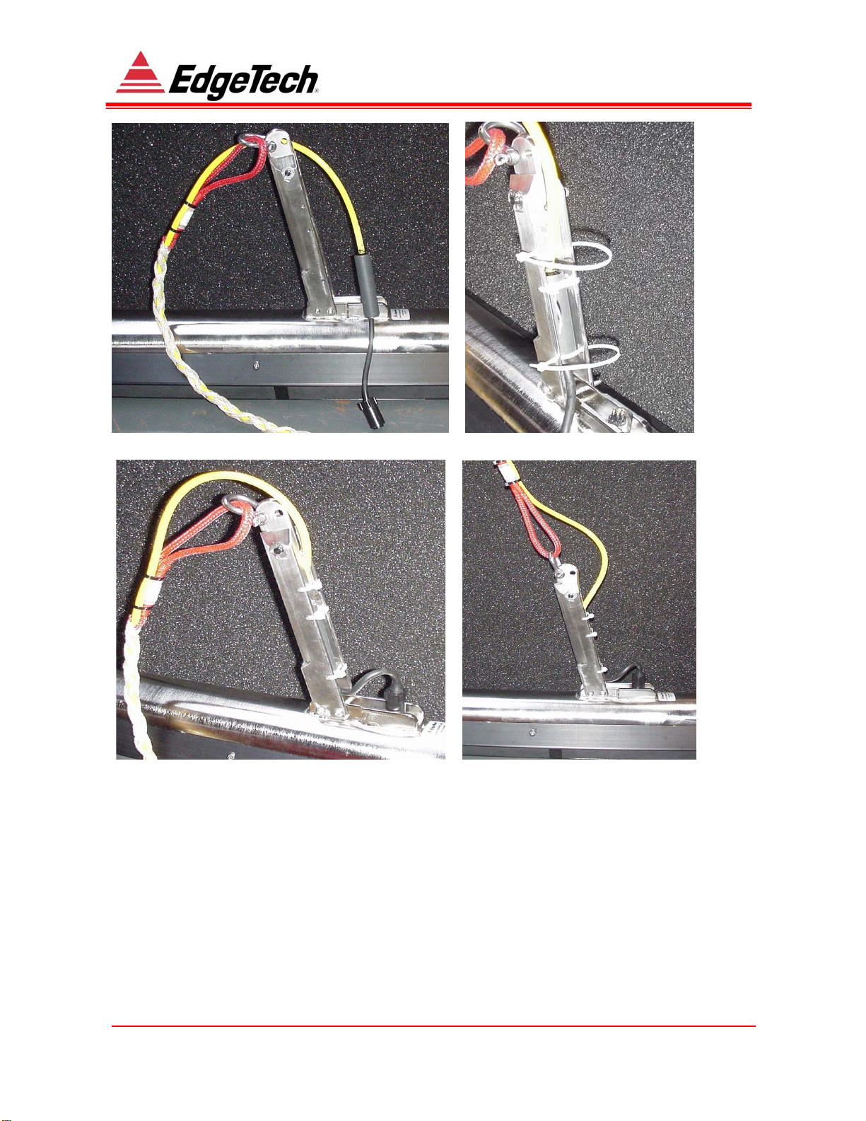
FIGURE 6-4: TOW ARM AND FISH CONNECTION
The Kevlar tow cable is terminated in a customized splice, which incorporates the 6 pin
female mating connector. This splice/connector combination is mated to the towfish (3 & 4),
and the splice is stored in the tow-arm cavity (2, 3 & 4). The cable is retained in the tow arm
using tie wraps (2 & 3)
Note: The maximum recommended tow speed using the supplied Edgetech coaxial
Kevlar cable is 8 knots.
For speeds in excess of 8 knots up to 12 knots we recommend the use of steel armored
cable, See Section 6.1.

Document: 990-0000046-1000 Page 10
4
42
20
00
0-
-F
FS
S
S
Si
id
de
e
S
Sc
ca
an
n
S
So
on
na
ar
r
6.1 OPTION 2(STEEL ARMORED TOW CABLE)
This option is used with the standard Edgetech tow-arm, as in Section 6.1
Higher speeds and depths maybe achieved using an armored tow cable.
6.2.1 CABLE ATTACHMENT
Tow cable attachment arrangements as follows.
FIGURE 6-5: ARMORED CABLE ATTACHMENT
The armored cable termination should be in accordance with the drawing in Section 8.

Document: 990-0000046-1000 Page 11
4
42
20
00
0-
-F
FS
S
S
Si
id
de
e
S
Sc
ca
an
n
S
So
on
na
ar
r
7TROUBLESHOOTING & REPAIR
This section provides information on isolating problems to the major component or subassembly
level. Once the problem area is isolated, the defective item should be replaced and returned to
EdgeTech for disposition. It is recommended that a complete set of spare boards and replaceable
subassemblies be kept onboard or at a readily accessible service center or depot facility.
The circuit boards contain static-sensitive devices. These devices are extremely sensitive to
static electrical charges that may develop on the body and clothing. Extreme care should be
taken when handling these components. Use anti-static protection materials and personnel
grounding straps during handling.
It is recommended that all attempts be made to see if a problem is external to the towfish
before opening it. Only open the towfish body as a last resort when it has been established
that the problem is internal to the towfish.
7.1 ACCESS/REMOVAL
Follow the procedures below to gain access to the internal components. Reverse the order to
reassemble. Note: Except for the transducers, all external hardware is mounted to the towfish
body with 4mm socket hex bolts.
Warning
Potentially Lethal Voltages Are Present in the Instrument
when it is powered from the topside or any other power unit.
7.1.1 TOOLS
Tools for access and service include:
•Phillips-head screw driver #2 (1)
•Flat-blade screw driver 1/8
•Socket driver 8mm (1)
•Allen key 4mm (1)
•Needle-nose pliers (1)
•Silicone grease (1)
•O-ring 2-154 N1470-70 (1)
Note: (1)These items are included in spares kit
7.1.2 PRELIMINARY
Prior to servicing the towfish, disconnect the mechanical and electrical connections to the tow
cable. Protect all disconnected underwater connectors. Ensure that they are kept clean and

Document: 990-0000046-1000 Page 12
4
42
20
00
0-
-F
FS
S
S
Si
id
de
e
S
Sc
ca
an
n
S
So
on
na
ar
r
lightly coated with silicone grease. Do not pack female connectors with grease unless the system
is to be put in long term storage.
7.1.3 ELECTRONICS ASSEMBLY REMOVAL
The electronics assembly is accessed from the aft section of the towfish body. This should be
done only in a clean, dry location. Proceed as follows to remove the electronics section.
1. Towfish electronics chassis is removed from the tail. There is no reason to remove the
nose section.
2. Remove tail fins (4mm Allen key) Fig 7-1
3. Remove the 4 bolts holding the plastic tail cone to the towfish (4mm Allen key) and
withdraw the tail cone from the end cap.
4. Attach handle (spares kit) to the end cap at the tail-cone bolt holes using two of the
removed bolts. Bolts do not have to be tight. See Figure 7-2
5. Carefully disconnect the four transducer connections on the end cap. Tag their ends as
to their placement.
6. Remove the screw securing a small metal block ( retention washer) located on the
topmost position near the rear end cap, see Figure 7-3
7. Remove the retention washer from the recess
8. Pull out the colored nylon retaining line with a pair of needle-nose pliers.
Note: If there is no exposed retaining line or the retaining line is cut and all the pieces
do not come out, pass a spare retaining line into the opposite end to expose and force
out any remaining pieces.
9. Pull on the handle and slide out the electronics to about 13 cm (5 inches) maximum.
Note: If there is a vacuum build up within the electronics housing that hinders removal,
remove the pressure relief port located between the 2 top connectors on the end cap to
relieve the pressure.
10. Disconnect the two inline connections for the power & telemetry cables near the end
cap.
11. Pull out the remaining electronics.
Table of contents
Other Edgetech Marine Equipment manuals

Edgetech
Edgetech 3300 User manual

Edgetech
Edgetech 3100 User manual

Edgetech
Edgetech 3400 User manual

Edgetech
Edgetech STARMUX IV User manual

Edgetech
Edgetech 2300 User manual

Edgetech
Edgetech 8242XS User manual

Edgetech
Edgetech 3200-XS User manual

Edgetech
Edgetech 3400 User manual

Edgetech
Edgetech 2050-DSS User manual
Edgetech
Edgetech 4380 MULTIBEACON User manual

Edgetech
Edgetech STARMUX IV User manual

Edgetech
Edgetech 3200-XS User manual

Edgetech
Edgetech 701 DIGITAL LINK User manual

Edgetech
Edgetech 8011M User manual

Edgetech
Edgetech 6205S2 User manual

Edgetech
Edgetech 4125I User manual

Edgetech
Edgetech Model 3100P Sub-bottom Sonar System User manual

Edgetech
Edgetech Port Pop-Up User manual


