AE&T APPELLO A121APPX User manual
A121APPX,AL121APPX & MV121APPELLO
Alarm Toneand Voice AnnunciationSounder
1) Introduction
TheAppellotone andspeechannunciation
sounderhas threedifferentstyles inAC and DC.
·A121APPX&MV121 Sounder
·AL121APPXSounder-BeaconCombination
Sounder-BeaconCombination unitsare
availableaseitherahigh outputLED or
Xenon strobe.
TheseSounderunitsshareacommonsetof
functions:-
·4stages,eachstagecanrecordup to30
secondsofCD qualityaudio.
·Facilitytorecordviaanonboardmicrophone
or aline ininput.
·Therecorded messagecanbe played back
proceededeitherwithorwithoutthechoice
ofoneoffortyfive tones.
TheBeaconfunctionsareeither:-
·Xenon Strobe-1Hzflash rate
·LED-EitherSteadyor2Hzblink rate
2) Operating andMarking
All unitshavethefollowing operating
requirementsand limitations.
Unit Type No.Voltage Range Current
Sounderonlyoutputs
A121APPXDC24Vdc14-30Vdc1.51A
&MV121DC
MaxCurrent1.85A @30Vdc
A121APPXAC 115Vac90-260Vac542mA
&MV121AC230Vac90-260Vac 517mA
MaxCurrent668mA@90Vac
AL121APPXcombinedunit- Add selected
sounder&beaconcurrentstocalculatetotal
currentrequired.
Beacononlyoutputs
LEDBeaconDC24Vdc10-30Vdc157mA
MaxCurrent166mA@30Vdc
LEDBeaconAC115Vac90-260Vac60mA
230Vac90-260Vac 35mA
MaxCurrent60mA@90Vac
Xenon Beacon DC12Vdc 10-14Vdc500mA
24Vdc20-28Vdc250mA
Xenon Beacon AC115Vac+/-10%Vac100mA
230Vac+/-10%Vac 50mA
Operating Temp:-20 to+55°C
All unitsIPRating:Type4/4X/ 3R/13,IP66
MV121additionalIPRating:IP67
Marking:
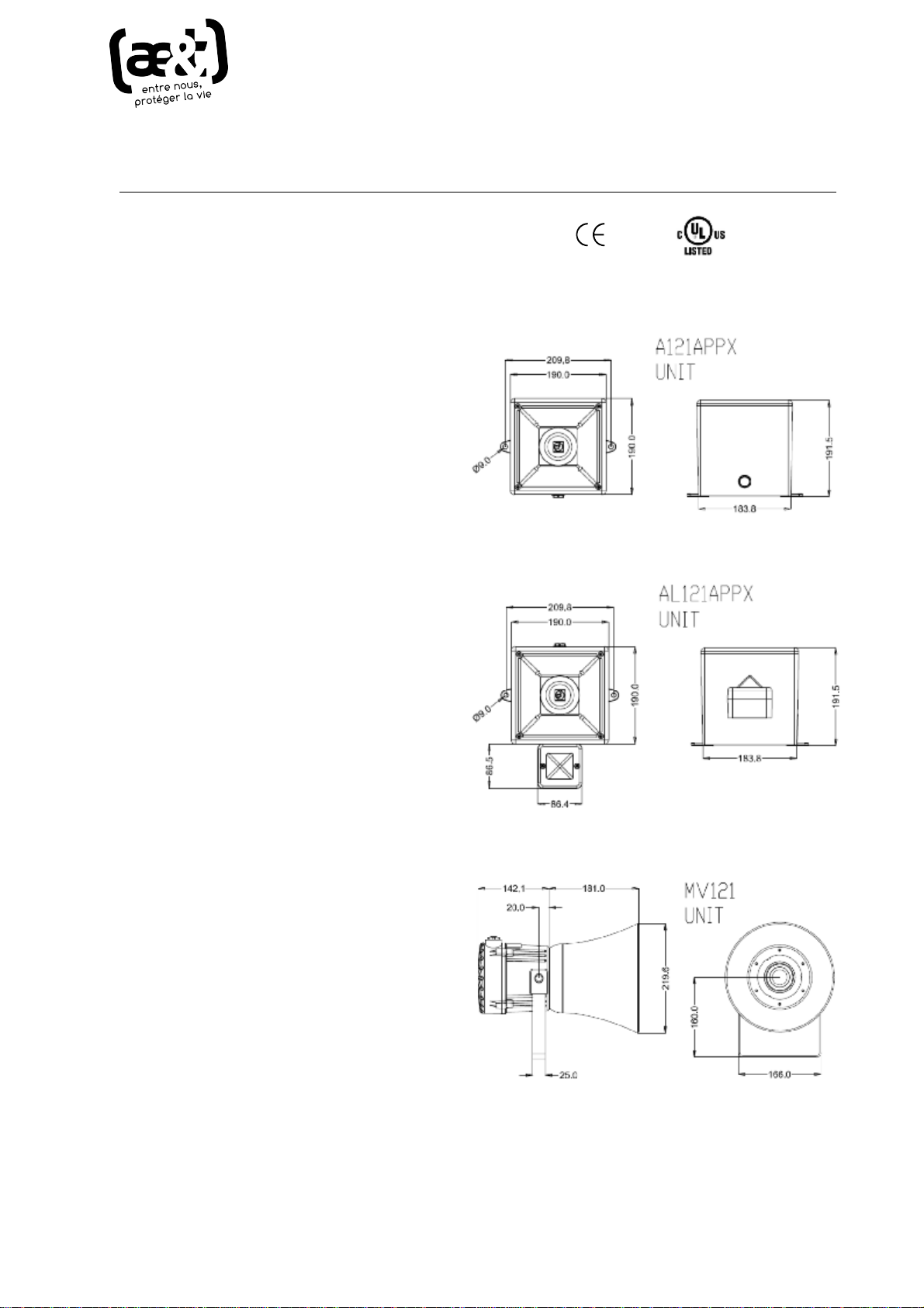
3)Installation&Wiring Requirements
A121APPX
AL121APPX
MV121
INSTRUCTION MANUAL
W>KϭϮϭͲĐŽŵŵĞƌĐŝĂůƌĞĨ
ϭϮϭyͲĨĂĐƚŽƌLJƌĞĨ
ae&t - 4 impasse Joliot Curie - 64110 Jurançon - tél 05 59 06 06 00 - [email protected] - aet.fr
Alwaysde-energizeunit beforeremovingcover.
Theinstallation ofthe unitsmustbein
accordancewithanylocalcodes thatmayapply
andshouldonlybe carried outbyacompetent
trained electricalengineer.
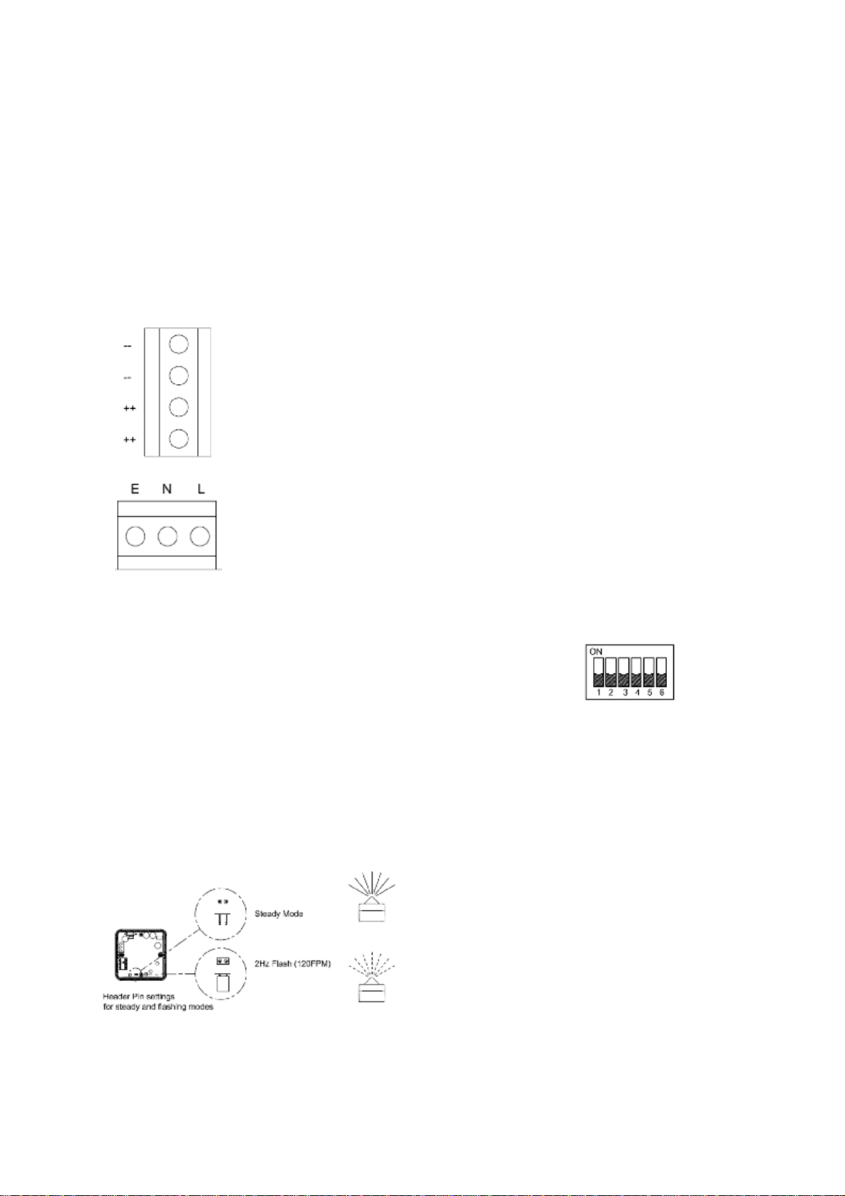
Thepowerterminalson thecontrolunitare
clearlymarked andwillacceptup to1.5mm
2
cable.
DCTerminals
on mainPCB.
++ =Positive
--=Negative
ACTerminals
On SubPCB
L=Live
N=Neutral
E=Earth
TheAL121unitswillhave the beacon already
prewired totheunitso noextrawiringisrequired.
4) BeaconSet-up
Thebeacon unit mayneed tobe configured
dependantonthe type offlashrequired.
Thexenonbeaconhasa1Hzflash rateonly.
TheLEDbeacon isset as standardtothe2Hz
flashmode butit can be settoasteadyon mode
also.To alterthe settings,change theposition of
the headerpinasshown.
·Remove header forsteadymode.
·Keep headerinstandardpositionfor
2Hzflashing mode
5)UnitSet-upandRecording
The unit will need tobeconfigured tosuit the end
user.
Ifrecordingeitherviatheonboardmicrophoneor
the in-line connectortheunit will need tobe
supplied withpower.
DCunitscanbepowered whencompleting
recording and set-up.
Warning!:During set-up onACunitscare
mustbetakennottotouchtheliveterminals.
Thisisbecauseon the ACunitsthereisarisk
ofelectricshock.
See section 7)AppelloSetup Guide overleaffor
Set-up instructionsand functions.
6)ToneSelectionTable
The Appellounit has45differenttones (See
Table1)thatcan beselectedforthe firststage
alarm.The systemscanthen beswitched to
soundsecond,thirdandfourthstage alarmtones.
The tonesareselected byoperationofaDIP
switch S4 onthemainPCB.
The tonetable(Table1)showsthe switch
positions forthe45tonesand whichtonesare
availableforthe secondthirdand fourthstages.
Example
S4DipSwitch-
ShownSetfor Tone 1
(All switches OFF)
Tosound stage onesimplyconnectthesupply
voltage(+veand–ve)forDCunitsand (L,N,E)
forAC units,tothe supplyinputterminalsonthe
correctPCB shown.

DCUnitsSecond,Thirdand FourthStage
Selection
TheAppellounituses–ve switching tochange
the tone tothesecond,thirdand fourthstages.
Warning!:The negativesupplymustremain
connectedtothe-(ve)terminalandalink
made fromthistotheappropriatestage (S2)
terminalotherwise theunit will bedamaged.
Tochange tothesecond,thirdorfourthstage
tone,link the -ve supplyline toterminalrelevant
stageterminal. Ie.forStage 2link the -ve supply
tothe S2 terminal, forStage3link the-ve supply
tothe S3terminal etc.
ACUnitsSecond,Thirdand FourthStage
Selection
The Appellounit usesLive switching tochange
the tone tothesecond,thirdand fourthstages.
Tochangetothe second,thirdorfourthstage
tone,whilstmaintainingthe acsupplytothe Live
and neutral, also link the Livesupplyline to
terminalrelevantstageterminal.i.e.forStage 2
link the Live supplytothe S2 terminal, forStage3
link the Live supplytothe S3 terminaletc.
AL121
BEACON ON
AL121
PRE-WIRED
INTERNALLY
BEACON ON
AL121
PRE-WIRED
INTERNALLY

INSTRUCTION MANUAL
A121APPX,AL121APPX & MV121APPELLO
Alarm Toneand Voice AnnunciationSounder
S4-Tones S2-Set-up ACPower&AlarmStage Terminal
Function L.E.D's
Jumper
DCPower&Alarm
Stage Terminal
Onboard AlarmTone &
microphone(Voice) RecordedContentVolumeControls
AudioLine-incPeaklevel L.E.D
DC A121APPX, MV121&AL121APPXBoard ACA121APPX,MV121&AL121APPXBoard
7)AppelloSetup Guide
The following guide isdesigned toget theuserquicklyinterfacingwiththeAppellounit.
·The Appellounitcanbe set-uptoeither playanattention seekingtoneand thenarecorded
message orjustplaythe recorded message.
·The usercan:
oRecordon eachof the4stages using either the LineInorMicrophone inputs
oSelecttherequiredalarmtone
oDeleteunwantedmessages.
·Tore-recordamessageon aparticularstage,theprevious message onthatstagemust be
deletedfirst.
·Oncethe user hasconfiguredthe unit,itmustbeput intoit'sPlayback ModeandS2 switches set
tostage1,asshowninQuickRef- Playback Mode(Stage1illustrated)guidebelow.
·The “MassErase”functionwillerase all therecorded stages.
·The"Mass Erase"canalsobe usedto reset theunitifany functionality is lost.
Quickref-Switch‘S2’DipSwitch Function Settings
Switch
No.
OFF Position
Function
ONPosition Function
1 RecordMode Playback Mode
2
Stage selection switch Switch 2On&Switch 3On=AlarmStage 1
Switch 2Off&Switch 3On=AlarmStage 2
Switch 2On&Switch 3Off =AlarmStage 3
Switch 2Off&Switch 3Off =AlarmStage 4
3 Stage selection switch
4 Line-InselectedOnboardMicrophoneselected
5 Program–Record&
Erase ModeON Playback –Record&Erase Mode OFF
6 Message&Tone
Playback MessageonlyPlayback
7 SingleMessageor
MassErase ModeOFF SingleMessage orMassEraseMode ON
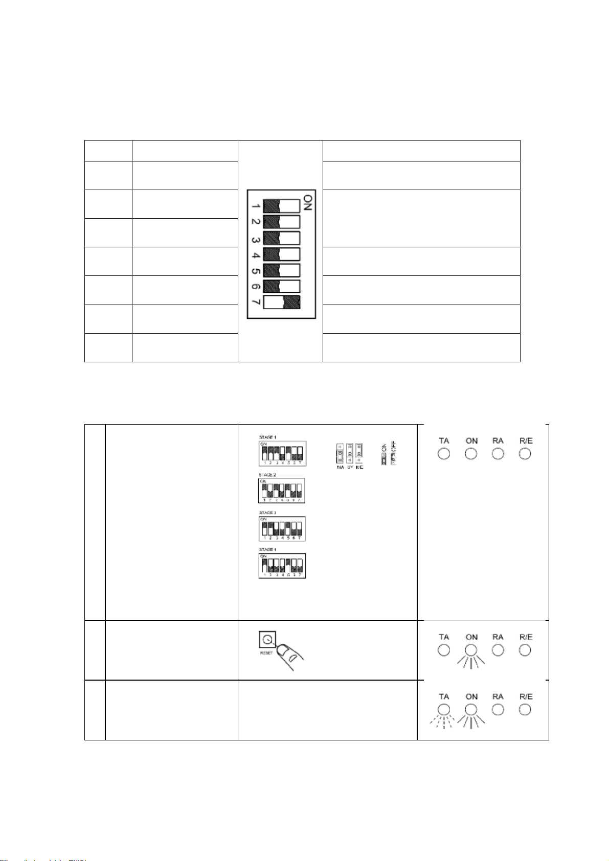
QuickRef- Playback Mode (Stage 1illustrated)
1
ForStage1:
SetSwitch‘S2’positions
1,2,3&5to'ON'
Alternativelyfor :
ForStage2:
SetSwitch‘S2’positions
1,3&5to'ON’
ForStage3:
SetSwitch‘S2’positions
1,2&5to'ON'
ForStage4:
SetSwitch‘S2’positions
1&5to'ON'
2 Switch on poweror
Press resetbutton
3a
Unit will sound alarmtone
andthen recorded
contentrepeatedly

QuickRef- RecordingMode (Stage 1illustrated)
1
ForStage1:
SetSwitch‘S2’positions
2,3&4to'ON'
Alternativelyfor :
ForStage2:
SetSwitch‘S2’positions 3
&4to'ON'
ForStage3:
SetSwitch‘S2’positions 2
&4to'ON'
ForStage4:
SetSwitch‘S2’position 4to
'ON'
TorecordfromLine-in
insteadof theonboard
microphonefollow above
step 1but setSwitch ‘S2’
position 4toOFF
2 Switch on poweror
Press resetbutton
3a Press action button:
Startrecording
3b
Speak intomicrophoneor
plug line-in.
Itissuggestedthata5cm
gapismaintained tothe
microphone.
Thepeakdetector L.E.D
shouldflashregularlyto
maintainagood recording
level.
However, ifit stayson for
mostof the time, the
recordingmaybedistorted.
4 Press action button:
Stop recording

QuickRef- Erase SinglestageMode (Stage1illustrated)
1
ForStage1:
SetSwitch‘S2’positions
2,3&7to'ON'
Alternativelyfor :
ForStage2:
SetSwitch‘S2’positions
3&7to'ON'
ForStage3:
SetSwitch‘S2’positions
2&7to'ON'
ForStage4:
SetSwitch‘S2’position 7
to'ON'
2 Switch on poweror
Press resetbutton
3a Press action button:
Erase willbegin
3b -- -- erase complete


QuickRef- SynchronisingTwoSounders(Allstages)
1 ConnectSynch cableto
Masterand Slave PCB
2
Set1offUnitsasMaster
and1off UnitasSlave
SetjumpertoSYon
SetjumperMA onMaster
unittomasterposition
(on)
SetjumperMA onSlave
unittoslaveposition (off)
Position of S2switch
does not affectsynch
operation.
3
Switch on powerontothe
Masterunitfirst
Then switch poweronto
the Slaveunit
MasterUnit
SlaveUnit
4a
Press action button onthe
MasterUnit:
Synchronisation willbegin
(Duration 13 Minutes)
MasterUnit
SlaveUnit
4b
-- -- Synchronisation
complete
Switch off Powertounits
MasterUnit
SlaveUnit
5
Reseton bothunits
jumperSYtooff
SetjumperMA onboth
unitstoMasterposition
(on)
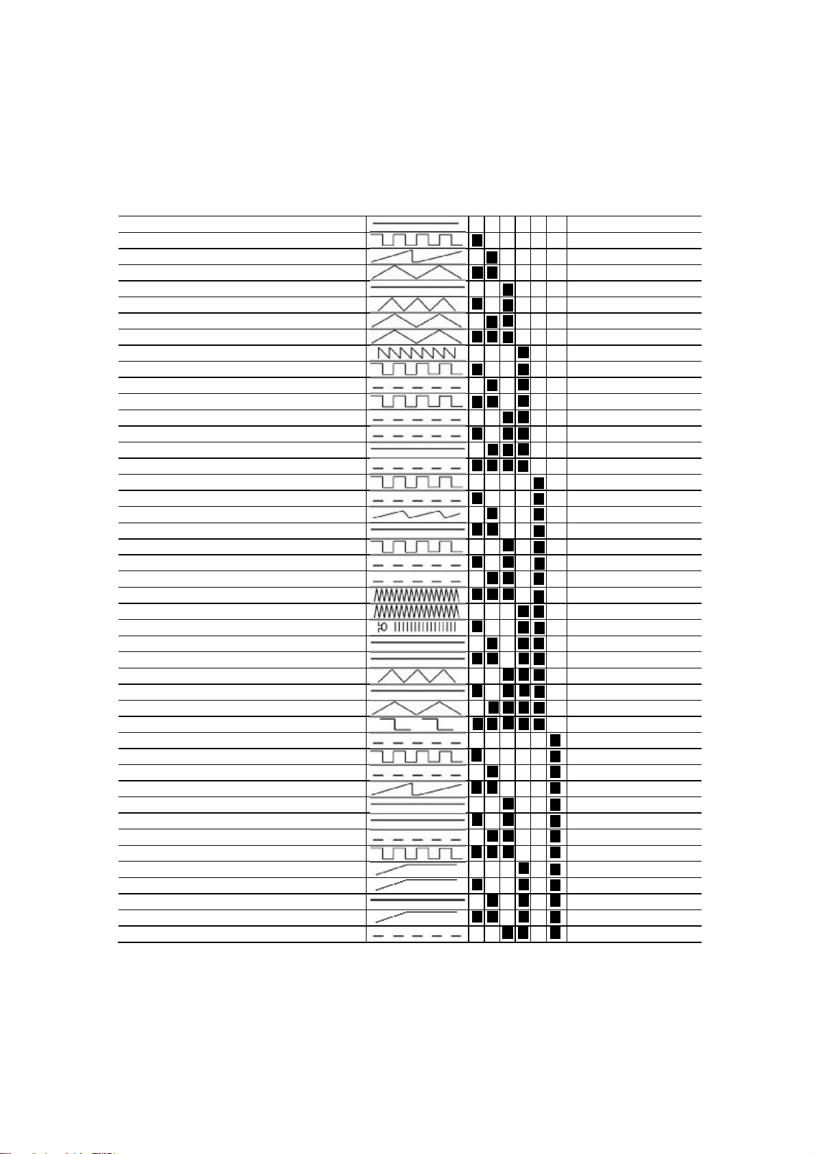
Table1:Toneselectiontable
Switch Stage2 Stage3 Stage4
Stage1Frequency Description 123456 (S2) (S3) (S4)
Tone 1 340HzContinuous
Tone 2 Tone5 Tone 29
Tone 2 800/1000Hz@0.25 secAlternating
Tone 17 Tone5 Tone 29
Tone 3 500/1200Hz@0.3Hz0.5 secSlowWhoop
Tone 2 Tone5 Tone 29
Tone 4 800/1000Hz@1HzSweeping
Tone 6 Tone5 Tone 29
Tone 5 2400HzContinuous
Tone 3 Tone20 Tone 29
Tone 6 2400/2900Hz@7HzSweeping
Tone 7 Tone5 Tone 29
Tone 7 2400/2900Hz@1HzSweeping
Tone 10 Tone5 Tone 29
Tone 8 500/1200/500Hz@0.3HzSweeping
Tone 2 Tone5 Tone 29
Tone 9 1200/500Hz@1Hz-DIN/ PFEERP.T.A.P.
Tone 15 Tone2 Tone 29
Tone 102400/2900Hz@2HzAlternating
Tone 7 Tone5 Tone 29
Tone 111000Hz@1HzIntermittent
Tone 2 Tone5 Tone 29
Tone 12800/1000Hz@0.875HzAlternating
Tone 4 Tone5 Tone 29
Tone 132400Hz@1HzIntermittent
Tone 15 Tone5 Tone 29
Tone 14800Hz0.25secon, 1secoffIntermittent
Tone 4 Tone5 Tone 29
Tone 15800HzContinuous
Tone 2 Tone5 Tone 29
Tone 16660Hz150mSon,150mSoff Intermittent
Tone 18 Tone5 Tone 29
Tone 17544Hz(100mS)/440Hz(400mS)-NFS32-001
Tone 2 Tone27 Tone 29
Tone 18660Hz1.8secon,1.8secoffIntermittent
Tone 2 Tone5 Tone 29
Tone 191.4KHz-1.6KHz1s,1.6KHz-1.4KHz0.5s-NFC48-265
Tone 2 Tone5 Tone 29
Tone 20660HzContinuous
Tone 2 Tone5 Tone 29
Tone 21554Hz/440Hz@1HzAlternating
Tone 2 Tone5 Tone 29
Tone 22544Hz@0.875sec.Intermittent
Tone 2 Tone5 Tone 29
Tone 23800Hz@2HzIntermittent
Tone 6 Tone5 Tone 29
Tone 24800/1000Hz@50HzSweeping
Tone 29 Tone5 Tone 29
Tone 252400/2900Hz@50HzSweeping
Tone 29 Tone5 Tone 29
Tone 26Bell
Tone 2 Tone15 Tone 29
Tone 27554HzContinuous
Tone 26 Tone5 Tone 29
Tone 28440HzContinuous
Tone 2 Tone5 Tone 29
Tone 29800/1000Hz@7HzSweeping
Tone 7 Tone5 Tone 29
Tone 30300HzContinuous
Tone 2 Tone5 Tone 29
Tone 31660/1200Hz@1HzSweeping
Tone 26 Tone5 Tone 29
Tone 32Two tone chime.
Tone 26 Tone15 Tone 29
Tone 33745Hz@1HzIntermittent
Tone 2 Tone5 Tone 29
Tone 341000&2000Hz@0.5secAlternating-Singapore
Tone 38 Tone45 Tone 29
Tone 35420Hz@0.625secAustralianAlert
Tone 36 Tone5 Tone 29
Tone 36500-1200Hz3.75sec/0.25sec.Australian Evac.
Tone 35 Tone5 Tone 29
Tone 371000HzContinuous-PFEERToxicGas
Tone 9 Tone45 Tone 29
Tone 382000HzContinuous
Tone 34 Tone45 Tone 29
Tone 39800Hz0.25secon, 1secoffIntermittent
Tone 23 Tone17 Tone 29
Tone 40544Hz(100mS)/440Hz(400mS)-NFS32-001
Tone 31 Tone27 Tone 29
Tone 41MotorSiren -slowriseto 1200Hz
Tone 2 Tone5 Tone 29
Tone 42MotorSiren -slowriseto 800Hz
Tone 2 Tone5 Tone 29
Tone 431200 HzContinuous
Tone 2 Tone5 Tone 29
Tone 44MotorSiren -slowriseto 2400Hz
Tone 2 Tone5 Tone 29
Tone 451KHz1son, 1soff Intermittent -PFEERGen. Alarm
Tone 38 Tone34 Tone 29
This manual suits for next models
2
Other AE&T Marine Equipment manuals


