Hydrophase Ridesteady User manual

PRODUCTGUIDE


Table of Contents 1
Package Contents.......................................................................................................................................2
Overview .......................................................................................................................................................4
Installation Guide
Electrical Connection Diagram ...............................................................................................5
Throttle Node / RPM Cable Install..........................................................................................6
Display / GPS Receiver Install ..................................................................................................8
Temperature Sensor Install.......................................................................................................9
Power Cable / CPU Install........................................................................................................10
CPU Power / Test ........................................................................................................................11
Operation Guide
Overview.......................................................................................................................................12
Usage Procedure........................................................................................................................13
Main Screen .................................................................................................................................14
Standby Screen...........................................................................................................................16
SETTINGS Menu..........................................................................................................................17
Appendix
Wire Tapping & Troubleshooting..........................................................................................21
Purchase Agreement ................................................................................................................22
Limited Warranty........................................................................................................................23
Ridesteady_Installation_and_Users_Guide_Yamaha_v.1.03
August, 2017

2 Package Contents
Package contents: items may appear slightly different than shown.
Display / keypad
CPU
GPS assembly
STBD Throttle Node
PORT (or SNGL) Throttle Node

Package Contents 3
CPU-to-Node cable
“Throttle” cable
#6 wood
screws
8” zip ties (cable tie)
8” mounted head zip ties (cable tie)
Power cable
[Optional] Air temp sensor [Optional] Water temp sensor
Tap connectors
RPM cable(s)
Node-to-Node cable

4 Overview
Congratulations on your purchase of the Ridesteady speed
control system! Your system was designed specifically for
use on Yamaha jet boats to provide high performance,
easy-to-use operation.
GPS or RPM-based control
The Ridesteady speed control system uses information
from satellite-based “Global Positioning System” (GPS) and
“Global Navigation Satellite System” (GLONASS) to control
the boat speed. The dual, simultaneous use of both GPS
and GLONASS systems allow for unprecedented precision
and control.
RPM-based control allows for super-smooth operation,
useful for slalom skiers or barefooters at higher speeds, or
tubing at any speed. It also maximizes fuel efficiency when
cruising in choppy water.
Ease-of-use
The Ridesteady user interface provides an experience
unmatched in the industry. A high resolution, weather and
splash-proof optical rotary encoder provides incredibly fast
and easy adjustments. 50 custom user-profiles allows you
to dial-in your speed, pull, and control-method preferenc-
es, and saves your day and all-time“Ridestats”.
Engine synchronization
Advanced technology is designed into the Ridesteady
speed control system to allow synchronization of the
engines on twin-engine boats.
Throttle reduction technology
Hardware-based throttle reduction technology electroni-
cally prevents Ridesteady from giving more throttle than
the amount of throttle the driver provides, for a safe oper-
ating environment.
Timed-standby
The industry-first timed-standby keeps the GPS active
while reducing power when the ignition switch is OFF. This
keeps the power consumption low while continuing to
track satellites, allowing for instant restart. It also dis-
plays GPS time, air and water temps, battery voltage, and
elapsed and remaining time.
Ridestats™
“Ridestats”track the user’s current ride-time, day ride-time,
and all-time ride-time. It also displays the percentage of
ride-time compared to all other users for the day, and all-
time. Use this feature to promote ride-time fairness, gas
sharing, training time, or just-for-fun.
GPS-based compass
The GPS-based compass presents your heading in real-
time in an easy-to-read graphical format.
Air and water temperature
The optional air and water sensors display real-time
temperatures. It is possible to mount the sensors without
drilling a single hole using the existing pitot tube pickup
hole (if so equipped).
Engine hour meters with trip
Keep track of your engine hours with ease. The hour
meters feature independent, twin engine capability with
resettable trip meters, handy for maintenance interval
tracking.
Installation process
Detailed step-by-step instructions are included in this
manual to allow the mechanically-inclined boat owner to
install the Ridesteady speed control system successfully.
However, if you are not comfortable with performing pro-
cedures listed in this manual, you should seek the service
of a qualified boat technician.
The instructions are tailored to Yamaha jet boats. However,
there are some (usually minor) variations between models
and years, so there may be some difference between the
instructions and your particular boat. Contact support at
Hydrophase if you have any questions.
Read through this manual in its entirety before beginning
installation. Visit www.hydrophase.com to download this
instruction manual in PDF form with full color pictures.
Engine compatibility
This system was developed for use on Yamaha jet boats
with APS (Accelerator Position Sensor). Check www.hydro-
phase.com for more information.
We’re here for you!
If you have any questions or concerns regarding the instal-
lation or use of your Ridesteady speed control system, just
send us an e-mail or give us a call. We’re not satisfied until
you’re out on the water rippin’ it up!
e-mail: support@hydrophase.com
phone: 512-524-8686
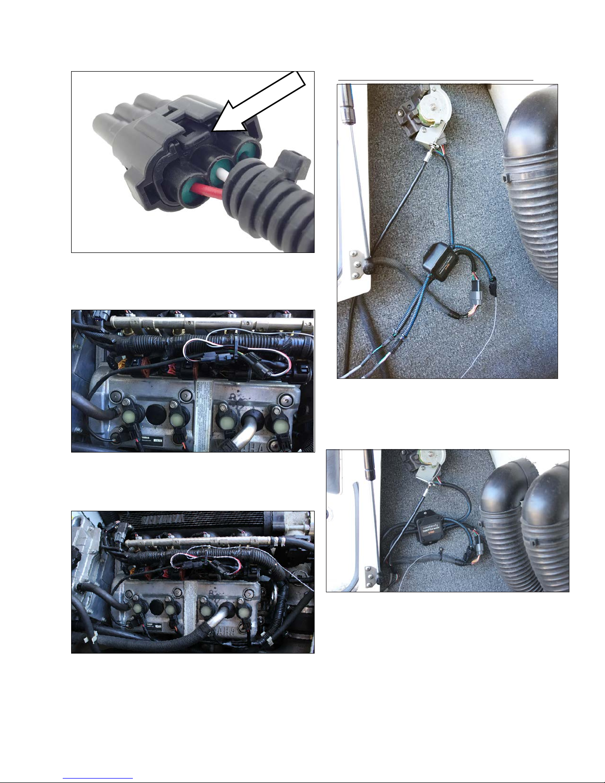
Installation procedures
1) Connect throttle node(s) to APS
2) Connect throttle nodes to CPS with RPM cable
3) Complete connections; mount throttle nodes
4) Mount in-dash display
5) Mount GPS receiver
6) Mount [optional] temperature sensors
7) Connect power cable
8) Mount and connect CPU
9) Power ON test

PORT
or STB
D
P
O
R
T
or S
TBD
BLK - Ground
To: BLK wire
R
E
D
-
Con
s
t
a
nt
12
V
To:
R
E
D wi
re
W
HT
-
swit
che
d 1
2V
To:
YEL
/
RE
D wire
s
GRN - Lights
To: BLU wire
Throttle Node
Power
Throttle
Air Temp
Paddlewheel /
Water Temp
LCD Display
GPS
RPM
PORT or SNGL
engine
STBD
engine
To: Cam
Position
Sensor (CPS)
To: Accelerator
Position Sensor
(APS)
To: Engine Wire
Harness (CPS)
To: Engine Wire
Harness (APS)
Throttle Node
To: Cam
Position
Sensor (CPS)
To: Accelerator
Position Sensor
(APS)
To: Engine Wire
Harness (CPS)
To: Engine Wire
Harness (APS)
Node-to-Node Cable
CP
U
-to-Nod
e
Cable
RPM Cable
RPM Cable
Electrical Connection Diagram 5

CPS
CONNECTOR
A
P
S
LATCH
CPS
6 Throttle Node / RPM Cable Install
2) Connect throttle node(s) to CPS with RPM cable
Step 1 Locate the Cam Position Sensor (CPS) on the engine (which
may be located under a cover). Follow the wire from the sensor to
the connector (typically a little over 12” away). Note that some con-
nectors are black while others are clear or“natural plastic” color.
Step 1 Locate the APS (Accelerator Position Sensor) for an engine.
They are located on the wall near the engine.
Step 3 Connect the corresponding STBD or PORT throttle node to
the APS, ensuring that the connector latch is engaged. Connect the
throttle node to the wiring harness, ensuring that the connector latch
is engaged.
Repeat steps 1-3 on the opposing engine for twin-engine boats.
Step 2 While pushing the wiring harness’s female connector latch
inward (which may be facing the wall), pull back on the connector
housing to disconnect it from the APS sensor (see Figure 5-1). It may
require a little“wiggling” to free.
Follow the steps below to install the throttle node(s). Make sure the
engine batteries are switched off. “Ground” yourself (by touching a
large metal object) before touching the throttle nodes or CPU, and
avoid touching the connector contacts to prevent possible accidental
“static electricity” (ESD) damage.
If your boat is used in salt water / salt environments, apply a thin
coating of electronic-grade di-electric silicone grease (not adhesive/
caulk!) to cover the surfaces of each of the contacts of the con-
nectors to prevent corrosion. Electronic grade di-electric silicone
grease may be obtained at most auto parts stores (such as Permatex
22058/81150/09980 or Permatex Bulb Grease).
WARNING: Route all wires away from engine ignition components,
high power VHF coax, or radios. These components may gener-
ate electrical interference that could interfere with the Ridesteady
system.
Avoid sharp edges, hot surfaces, and moving components when
routing wires.
1) Connect throttle node(s) to APS

LATCH
Throttle Node / RPM Cable Install 7
Step 2 While pulling the inner connector latch outward, gently pull
back on the CPS connector housing to disconnect it from the wiring
harness. It may require a little“wiggling” to free.
Step 3 Make a loop with the RPM cable so that the connectors align
with the CPS / wiring harness connectors. Connect the RPM cable
connectors to both the CPS and wiring harness, ensuring that the
connector latches are engaged. Secure with a “zip”tie.
Step 4 Route the gray RPM cable along the wire harness loom to
avoid electrical interference with ignition parts. Route and connect
to the corresponding throttle node. Secure with “zip”ties.
Repeat steps 1-4 on opposing engine for twin-engine boats.
Step 2 Mount the throttle node near the APS where it won’t get wet.
A 3/32” pilot hole may be drilled for the wood screws, though the
panel wood is often soft enough that a pilot hole is not necessary.
Note that there are status LEDs on the throttle node circuit board
near the entrance of the node-to-node cable (see Power ON test).
These LEDs can be used for troubleshooting, so it is convenient to
have the node-to-node cable pointing towards the front of the boat
so that they can be seen.
Use the “mounted head”zip ties to secure the cables so that they do
not pull on the throttle node connectors.
Repeat step 2 on the opposing engine for twin-engine boats.
Step 1 Route the node-to-node cable (for twin-engine boats) from
the STARBOARD to PORT throttle node, routing away from the en-
gines. Connect to the throttle nodes and secure with “zip”ties.
Route the CPU-to-node cable from the STBD throttle node to under
the helm. Connect to the throttle node and secure with“zip” ties.
3) Complete connections; mount throttle nodes

8 Display / GPS Receiver Install
Step 1 Remove the existing speedometer.
1. Unfasten the helm “meter cover” to access the gauges. The meter
cover screws on some boats are accessible from above the meter
cover, others have nuts accessible from underneath, while others
have screws accessible from the side.
2. Remove the nuts and back clamp / bracket securing the speed-
ometer from behind.
3. Disconnect the pitot tubing and/or electrical connections. Be
sure to fold/plug and clamp off the pitot tubing (a “zip”tie may be
used) to prevent water from leaking out of it. Tape off any removed
electrical connections with electrical tape to prevent accidental short
circuits.
4. Remove the speedometer.
Step 2 Install the in-dash display.
1. Remove the nuts and back clamp from the rear of the Ridesteady
display.
2. Insert the display into the hole in the dash. From behind the
dash, reinstall the back clamp and nuts.
NOTE: On some boat models the hole may need to be enlarged
(such as with a rotary tool and a “sanding drum”) in order for the
Ridesteady display to fit.
Step 1 Mount the GPS receiver
1. Determine a location underneath the windshield and above the
helm where the GPS receiver will be placed.
2. Route the GPS receiver wire under or around the meter cover to
under the helm where the CPU will later be mounted. If the wire is
run under the meter cover, a half-circle cutout may need to be filed
into it to prevent the wire from being pinched (a rotary tool may
help). Be careful not to pull on the connector to prevent it from com-
ing off.
3. Clean any residue from the gelcoat using a 50/50 mix of isopropyl
alcohol and water. Peel the backing off one side of the included VHB
tape and apply to the bottom of the GPS receiver. Peel the backing off
the other side of the VHB tape and push the GPS receiver down onto
the clean surface where the receiver is to be placed. Apply pressure.
For the best performance, mount the GPS receiver where only the
windshield or nothing is between it and the sky.
If mounting under fiberglass is preferred, make sure the top of the
GPS receiver is oriented towards the sky, and as little material is be-
tween it and the sky. For example, it is better to mount the receiver
so that the GPS signal only has to pass through fiberglass, rather than
fiberglass and windshield. Only mount where passengers will not
block the signal. If any “jerkiness” is experienced during use, the GPS
may need to be relocated.
Step 2 Keep meter cover unfastened until after power cable in-
stalled and CPU mounted in the coming steps.
4) Mount in-dash display 5) Mount GPS receiver

EXISTING HOLE
P
I
TO
T
P
IC
K
UP
Temperature Sensor Install 9
Air temperature sensor
The air temperature sensor should be located in a cool area shaded
from the sun. Typically the best location is underneath the helm,
away from any heat-producing devices such as amplifiers. It is recom-
mended to “hang”the temperature sensor from the cable a couple of
inches (with the included zip ties) so that the sensor will be influ-
enced primarily by the air temperature. Route the cable to where the
CPU will be located.
Position the white wire just inside the slot on right, denoted by the
small arrow (in circle above). The small “retention clip” of the contact
should be oriented downwards.
Position the other two wires (which may be black, clear, or bare) into
either of the next two adjacent slots, as shown.
Gently push the contacts all the way into the connector housing.
The small retention clips should be seen through the top rectangle
cutouts on the back of the housing, as shown.
FRONT BACK
6) Mount [optional] temperature sensors
Water temperature sensor
If the speedometer pitot tube is no longer being used (since the
speedometer was removed in prior steps), the tubing may be discon-
nected from the pitot pickup and pulled up into the boat. The water
temperature sensor cable may then be routed through the existing
hole. Apply marine sealant around the hole from inside the boat.
If no existing hole can be used, the water temperature sensor cable
may be passed through with a 3/16”hole (as high up as possible),
using a marine sealant to seal the hole.
The water temperature sensor should be mounted on the transom.
Clean any residue from the gelcoat using a 50/50 mix of isopropyl
alcohol and water. After the surface has dried, peel the VHB backing
off and place at the desired location. Apply pressure. It’s recommend
to wait 24 hours before putting the boat in the water to give the VHB
tape time to cure.
The water temperature sensor cable comes un-installed in the con-
nector housing to allow for a small hole in the transom. After the
cable has been routed through the transom, follow the instructions
to insert the contacts of the connector into the housing. Refer to the
pictures below for more information.
1. Locate the arrow on the top of the connector
2. Position the WHITE wire contact just inside the right-most con-
nector slot, denoted by the arrow. The small “retention clip” should
be oriented downwards.
3. Position the other two wires (which may be black, clear, or bare)
into either of the next two adjacent slots. Again, the “retention clip”
should be oriented downwards.
4. Gently push all the contacts into the connector housing. You
may hear a small “click” as the contact’s retention clips fit into place in
the small rectangular cutouts on the back of the housing. You should
see each retention clip protrude slightly from the rectangular cutouts.

10 Power Cable / CPU Install
Step 1 Find a dry, relatively cool location under the helm (i.e. don’t
mount on top of a stereo amplifier or speaker). The included wood
screws may be used to secure the CPU. A 7/64” pilot hole may be
drilled for screwing into fiberglass. Make sure all cables will reach the
CPU before mounting. Only mount to an “inside wall”.
Step 1 Unfasten the key-switch panel to access the key-switch wir-
ing.
1. Remove the screws securing the key-switch panel.
2. Pull the key-switch panel back to access the key-switch wiring.
Step 2 Connect the power cable to the key-switch wiring using the
included “tap connectors” (see appendix).
1. Connect the power cable’s black wire to either key-switch’s black
wire.
2. Connect the power cable’s red wire to either key-switch’s red wire.
3. Connect the power cable’s two white wires to each key-switch’s
yellow with red stripe wire (on some boats, it will be a solid yellow
wire). It doesn’t matter which white wire attaches to which key-
switch. On single-engine boats, simply tape off the second (unused)
white wire with electrical tape.
4. Connect the power cable’s green wire to navigation lights +12V.
Refer to the following information to find the appropriate wire.
How To Find Navigation Lights +12V Wire
If there was only a blue wire and a black wire going to the old
speedometer, the blue wire may be tapped into. The gray with
blue stripe wire coming from the navigation lights switch may
also be tapped into.
On newer boats with multifunction LCDs built in, or the smaller
version of “Connext” that does not have LIGHTS control , the gray
with blue stripe wire coming from the navigation lights switch
may be tapped into.
On boats with the full-size “Connext” systems (i.e. with LIGHTS
control), there is a gray with blue stripe wire labeled“ANCHOR
LT” in the SPU harness that may be tapped into. A 16 to 20 AWG
wire may be run to the SPU, which is often located under the
rear starboard seat (i.e. behind the driver’s seat). Tap one end
of the wire into the SPU’s ANCHOR LT wire, and the other end to
the Ridesteady LIGHTS wire.
Alternatively, the +12V wire on any light that comes ON when
the navigation lights are turned ON may be tapped.
The green Ridesteady LIGHTS wire automatically dims the dis-
play and is not necessary for any other operations. It may simply
be taped off with electrical tape if desired.
7) Connect power cable
8) Mount and connect CPU
Step 3 Route the connector-end of the power cable to under the
helm where the CPU will be located. Re-fasten key-switch cover.

CPU Power / Test 11
9) Power ON test
1. Switch the engine battery ON.
2. Turn an engine ignition key to the“ON” position (without start-
ing the engine). The blue LED on the CPU should light up and the
display should turn on, showing the Ridesteady logo and then the
main screen.
3. For twin engines, turn the key in the previous step OFF and turn
ON the opposing engine key (without starting). The display should
show the system going into standby, then turning ON again, thereby
demonstrating that both keys turn the Ridesteady system ON.
4. Verify that “ERR” is not shown on the main screen, but rather
“OFF”, “GPS”, or “RPM”. If ERR is shown, follow the guidance in Trouble-
shooting.
5. Start each engine independently for only a few seconds. Verify
that the engine(s) properly responds to the throttle lever(s) and that
the RPM is shown correctly on the Ridesteady display. Note that
the display will only show the“sync master” engine speed, which
can be changed in the SETTINGS. Follow the boat’s Owner’s Manual
procedures on running the engines out of the water, if the boat is not
in the water.
Make sure that bilge water is properly bilged at all times to prevent
any water from splashing up to the throttle nodes.
If the above tests are successful, the speed control is ready for an
on-the-water test run. Follow the procedures in the next section to
perform a trial run in a safe environment before officially using the
speed control full time.
The throttle nodes have status LEDs on the node-to-node cable side.
If everything is OK, a “blinking”green LED will be visible.
Step 2 Connect all cables to the CPU. Note that the power cable and
CPU-to-node (i.e. “Throttle”) cable have the same connector so be
sure to plug into the correct location.
Excess“slack” cabling may be coiled up and secured under or “behind”
the helm (i.e. towards the bow). Make sure that any coiled wire is
not being suspended by the connection to the CPU (i.e. prevent any
coiled wire from pulling down on the connectors). “Mounted head”
zip ties may be used to secure the cabling and provide strain relief as
needed.
Make sure the cables don’t cross over any sharp edges that may cut
into them with the normal vibration of the boat. Tape may be applied
to questionable areas to dull edges.
Step 3 Re-fasten meter cover.

!
12 Operation Guide: Overview
The Ridesteady speed control system was designed from
the ground up to be the easiest-to-use speed control sys-
tem available. However, it is imperative that every driver /
user of the Ridesteady speed control system read, under-
stand, and follow the instructions below to provide for the
safest operating environment possible.
The Ridesteady speed control system uses a “throttle re-
duction”method of manipulating the engine speed. When
properly installed, the system can only reduce throttle from
the amount of throttle provided by the driver. In other
words, the Ridesteady speed control system can only slow
down the boat from the amount of“gas”you give it, and
cannot speed up past that point. So, if at anytime you
would like to slow down or stop, simply pull back on the
driver’s throttle lever(s) as you normally would. The speed
control system will reset the throttle back to its original
position giving you manual throttle control.
The Ridesteady speed control system “remembers” the
state it was in prior to being powered OFF. If the speed
control was engaged when powered OFF, it will be en-
gaged when it is later powered ON. This feature simplifies
the operation of the speed control when the engine is
turned OFF and ON repetitively to allow riders and skiers to
enter / exit the boat. However, the driver must check the
speed control display when powering ON the engine to be
aware of its status.
Always follow the recommended procedures as outlined
by your boat manufacturer. Always run the bilge blowers
for the proper duration before starting the engine or while
travelling at low speeds.
Never operate a boat under the influence of drugs or
alcohol. Never attempt to operate the Ridesteady speed
control under the influence of drugs or alcohol.
Always properly attach the engine shut off cord (lanyard)
to your person. It may be pulled if any unexpected situa-
tions develop that require immediate slow down.
It is recommended to use RPM mode when travelling
under or near bridges, as the GPS signal can be temporarily
blocked, causing jerky operation or loss of fix.
It is not recommended to use any speed control where
fluctuations in speed may cause injury. Speed control
should not be used with “barefoot booms”.
Always keep your hand on the driver throttle lever(s) so
that you may slow down or stop at any time.
Button functions:
ON/OFF button
Toggles between manual-throttle (OFF) and
speed-control active (GPS, PW, or RPM).
SETTINGS button
Momentary press: moves cursor on main screen
Press and hold: enters / exits SETTINGS mode
(speed must be less than 5 MPH / 8 KPH to
enter SETTINGS mode)
Rotary / push knob
Momentary press: “ENTER”; toggles between:
cursor-move mode (cursor blinking)
setting-change mode (cursor solid)
Rotation: cursor-dependent:
in cursor-move mode: changes cursor position
in setting-change mode: changes setting
Display overview
The Ridesteady speed control system uses a 2 button with
rotary / push knob control panel with backlit graphical LCD
display.
WARNING

Operation Guide: Usage Procedure 13
5. Turn off the speed control to return to manual throttle
When it is desired to have “manual throttle” control, disen-
gage the Ridesteady speed control system by pressing the
ON/OFF button so that OFF appears. The throttle will now
behave like a normal manual throttle, without any speed
control. IMPORTANT: Disengaging the speed control will
reset the throttle; only disengage when the driver throttle
lever(s) is in the neutral position.
Traditional “cruise control” procedure
If it is desired to manually engage the speed control, the
speed control can behave similar to a typical automobile
cruise control.
Follow the same procedures as the “automatic speed
control”but accelerate slightly past the desired set speed
first, then press the ON/OFF button to engage the speed
control.
Throttle lever(s) position
It is only necessary to push the throttle lever(s) down
slightly more than is normally necessary to maintain the
desired set speed.
With the Yamaha APS throttle system, pushing the throttle
lever(s) all the way forward to the stops often induce a“sat-
uration” condition. That is, past a certain point, continu-
ing to push the throttle lever(s) forward will produce no
change in engine speed, but will continue to increase the
electronic throttle signal that the engine computer (ECU)
reads from the APS. This “extra throttle signal” can cause
a bigger overshoot on bring up, as Ridesteady has more
throttle that it must reduce in order to hit the set speed. If
you would prefer to push the throttle lever(s) to the stops,
try increasing the “overshoot” user setting to bring the
speed down faster if you experience bigger overshoot.
If the speed control slows down too much during the initial
acceleration, refer to the SETTINGS Menu page for informa-
tion on how to reduce the “overshoot” setting.
Engine synchronization [twin-engine boats]
When twin-engine synchronization is enabled in the SET-
TINGS, push both throttle levers forward approximately the
same amount. When the speed control takes over, it will
adjust the synchronization slave engine to the master en-
gine. However, it can only adjust approximately +/- 10% of
the throttle, so if the throttle levers are significantly apart,
the speed control may lose the ability to synchronize.
Simply adjusting the throttle levers back to approximately
even will rectify this situation.
The following procedures assume the engine is started and
that the rider / skier is ready to be towed behind the boat.
Automatic speed control procedure
1. Select user and adjust desired set speed
Move the cursor to highlight the user (if“CURSOR HOME:
USER is set, the cursor will already be highlighting the user
if below 5 MPH / 8 KPH). Rotate the knob to change the
user. This will load the set speed, control mode, response,
active speed and overshoot preferences for the selected
user. If it is desired to change the set speed, the cursor may
be moved to highlight the set speed and adjusted accord-
ingly. The set speed may also be adjusted while the speed
control is actively regulating the speed. If “SET SPD SAVE:
YES”is set, the adjusted set speed will be saved to the user.
2. Engage the speed control
Press the ON / OFF button to engage the speed control
system. The control mode will be displayed. If the control
mode is already displayed, the speed control system is
already engaged (the speed control system will remember
its status even after it is powered OFF). Warning: When
the speed control is engaged, the driver should be aware
that it will begin operating once a certain speed has been
reached.
3. Accelerate past the set speed to activate speed control
The Ridesteady speed control system uses a “throttle
reduction” method of manipulating the engine speed. The
driver must push down the throttle lever(s) slightly more
than is normally necessary to maintain the desired set
speed. Prior to reaching the set speed, the speed control
will begin controlling the throttle to avoid “overshooting”
the set speed by too much (this may be detected as a brief
reduction in speed). It will then regulate the throttle to
maintain the set speed. The rotary knob can be used to
adjust the set speed during operation. If the “MORE GAS”
screen appears, simply push the throttle lever(s) down
more to speed up a bit.
4. Pull back on throttle to slow down / reset throttle
When the rider / skier falls, or when you would like to
slow down or stop for any reason, simply pull back on the
throttle lever(s) as you normally would. The speed control
will attempt to maintain the speed until it falls below a cer-
tain threshold (determined by the set speed and other fac-
tors) and will then reset the throttle. The “THROTTLE RST”
screen will appear on the display, counting down until the
throttle is back to the original position. The current user’s
Ridestats will be displayed simultaneously. If the SETTINGS
button is pressed, it will extend the throttle reset screen by
5 seconds for each press (max: 10s). The speed control will
remain engaged and ready to “take over” again when the
driver begins to accelerate towards the set speed again.

GPS Status Indicator:
• # bars: signal precision estimation
• top #: number of satellites tracking
“+” indicates 10 or more satellites
• bottom “D”: differential-GPS lock
Speed Display Source:
• GPS
• can be set independent of
speed-control source
Set Speed:
• adjustable from 8 MPH to 50 MPH
(13 KPH to 80 KPH) in
0.1 MPH / KPH increments
• settable before or “on the fly”
• cursor always switches to set speed
above 5 MPH / 8 KPH
Engine Speed:
• shows speed of single engine, or
“sync master” engine on twin-engine
applications
Control Mode:
• GPS, RPM, or OFF
User:
• 50 user presets
• 10-character name
• set speed
• control mode
• response preference
• active speed
• overshoot preference
• day ridetime
• all ridetime
• “cursor home” can be set here so user is
easily switched below 5 MPH / 8 KPH
GPS Time:
• GPS-synchonized time
Ridestats:™
• top #: user’s run (current) ride-time
• bottom #: user’s total day ride-time
Temperatures:
• top #: air temperature
• bottom #: water temperature
• degrees C or F
GPS Compass:
• GPS-calculated heading
ON / OFF button :
• manual throttle or speed control active Settings button:
• momentary press: moves cursor
• press and hold: enters / exits SETTINGS
mode
Rotary / push knob:
• high resolution, weatherproof,
splashproof optical encoder
• moves cursor or changes settings
• easy-to-use
14 Operation Guide: Main Screen Overview

Operation Guide: Main Screen 15
User: Shows the active user. The
50 user profiles contain:
• 10-character name
• set speed
• control mode
• response
• active speed
• overshoot
• day ride-time (accessed in “Ridestats”)
• all ride-time (accessed in “Ridestats”)
If SETTINGS are set to“CURSOR HOME: USER”, the cursor
will automatically move from the set speed to the user be-
low 5 MPH / 8 KPH so that the user is easily changed with a
rotation of the knob. Otherwise, the cursor may be moved
to this area and the user changed.
The default user names are GUEST.01 through GUEST.50.
There are also “system users”, SYS.RPM, SYS.GPS. These us-
ers can be accessed by rotating the knob counterclockwise
to the first user (GUEST.01 by default), waiting a second,
then continuing to rotate the knob counterclockwise. This
creates a“digital stop” which makes it easy to access the
first user without inadvertently going into the system us-
ers. The “system users”are provided to allow usage of the
speed control without using a saved user.
GPS Time: GPS-synchronized time. The
timezone and daylight savings time can be changed in
SETTINGS.
Ridestats:™ The top number shows the user’s
current ride-time. The bottom number shows the user’s to-
tal ride-time for the day. The ride-time starts when the set
speed has been reached. The day ride-time will automati-
cally be reset at midnight.
Temperatures: The top number shows the
air temperature while the bottom number shows the water
(lake) temperature. The water temperature is received
through either the paddlewheel or the water temperature
sensor. If using the water temperature sensor, the paddle-
wheel must be turned OFF in SETTINGS to load the proper
calibration curve.
GPS Compass: GPS-calculated head-
ing shows your“course-over-ground”in graphical form.
The compass works at about 5 MPH and above, and may
be erratic at speeds less than that. The compass should not
be used for life-critical navigation.
Main Screen - referenced from the previous page
GPS Status Indicator: Provides a quick status of the
GPS signal.
The bars indicate an estimation of the quality of the signal.
This estimation is based on many variables including the
signal strength and geometry of the GPS satellites “visible”
to the GPS receiver. 2 to 3 bars will typically give an excel-
lent speed signal and thus an excellent pull.
The top number, denoted as “+” sign here, indicates how
many satellites are being used to calculate the speed. The
“+” sign indicates 10 or more satellites.
The bottom“D” will appear when the system is using
differential-GPS (known as “WAAS” or Wide Area Augmen-
tation System in North America) to improve GPS accuracy.
Differential-GPS may not be available in all areas, and is not
necessary for speed control operation.
Control Mode: [OFF, GPS, RPM]
Shows whether the speed control is active and which
speed source is input into the speed control. If OFF is not
shown, the speed control is engaged and will regulate the
set speed based on the selected control mode. If ERR is
shown, follow the guidance in Troubleshooting.
The ON/OFF button toggles the control mode between
OFF and GPS or RPM. The control mode is determined by
the current user. If the cursor is moved to this area, the
control mode may be changed directly, which will cause
the user to change to a“system user” [SYS.RPM, SYS.GPS].
System users can be thought of as“temporary” users when
you don’t want to use a saved user.
Speed with Speed Display
Shows the current speed based on the selected“speed
display source”.
Set Speed with Speed Units:
Shows the set speed along with the speed units [MPH /
KPH]. If the cursor is moved to this area, the set speed may
be changed directly. If SETTINGS are set to “SET SPD SAVE:
YES”, the changed set speed will be saved to the user pro-
file. If SETTINGS are set to “SET SPD SAVE: NO”, the changed
set speed will not be saved to the user profile.
Engine Speed: Shows the en-
gine speed in revolutions per minute (RPM). With twin-en-
gine applications, the“sync mstr” setting determines which
engine’s speed will be shown. Note that needle-based
tachometers often have some inaccuracies, so it may not
match perfectly with the RPM speed Ridesteady reports.

GPS Status Indicator:
• continues to track satellites
• # bars: signal precision estimation
• top #: number of satellites tracking
“+” indicates 10 or more satellites
• bottom “D”: differential-GPS lock
Standby Time:
• top: elapsed time
• bottom: time remaining until
automatic power kill
GPS Time:
• GPS-synchonized time
• Large font for easy boat-wide viewing
Temperatures:
• top #: air temperature
• bottom #: water temperature
Battery Voltage:
• Monitor battery voltage
ON / OFF button :
• instantly kill power
Settings button:
• extend standby time
by 5 minutes per press
16 Operation Guide: Standby Screen
Standby Screen - When the ignition SWITCH is turned
OFF, the system will enter standby-mode and the“standby
screen” will appear (as shown above).
Standby-mode allows the GPS to remain active while run-
ning in a lower power mode. This allows for continuous
satellite tracking for instant restart and useful informa-
tion display such as the time (in large font), air and water
temperatures, battery voltage, and elapsed-time and
countdown-time, all in a lower power environment.
Standby-mode is useful in-between sessions to keep the
GPS active and while “floating”, to keep track of the time,
temperature, and battery voltage. It can also be used
when trailering to the boat ramp--this way the GPS will be
actively tracking satellites by the time the boat is in the
water.
Pressing the power button in standby mode will instantly
“kill” the power to the system. Killing power to the system
under 1 minute from engine power OFF may cause the
engine computer to turn ON the check engine light. If this
occurs, simply wait a few minutes for the check engine
light to turn OFF before restarting the engine. Pressing the
settings button will extend the countdown timer 5 minutes
each press, up-to 250 minutes.
The “PWR OFF DELAY” setting may be set from 1 to 250
minutes.
When storing the boat, make sure the blue power LED is
OFF.

Operation Guide: SETTINGS Menu 17
Enters / Exits
MENU
Press & hold
2 seconds when
speed < 5 MPH
/ 8 KPH
settings
ridestats
user: 1
name: guest.01
# rides 7 174
time 18m 14.5h
ratio 34.7%
63.1%
user set
user: 1
name: guest.01
control mode: GPS
set speed: 20.0 MPH
response: 50
active spd: 1 mph
overshoot: 50%
system set
lcd contrast: 0
lcd blkt: 100%
lcd bklt lts on: 25%
beep volume: 50%
cursor home: set spd
set spd save: NO
timezone: -06 utc
daylt savings: no
pwr off delay: 30 min
speed units: mph
pw enabled: no
pw speed cal: 0.0 mph
temp units: deg f
air temp cal: 0.0F
lake temp cal: 0.0F
engine cyl: yam
in gps mode, show: GPS
in rpm mode, show: gps
in pw mode, show: pw
active beep: yes
NAV SAT: GPS+GLONASS
eng num: twin
eng sync: on
sync mstr: port
system info
engine hours
note status
battery
software
factory reset
user: 1
name: guest.01
reset stat above? No
reset user above? no
reset all stats? no
reset all users? no
reset system? no
reset everything? no
DAY
ALL
SETTINGS menu
Follow the guide below to customize the Ridesteady
speed control system to your preference. Often the
default settings provide the best result and require no
adjustments.
Older Ridesteady software versions may not contain all
the features listed here.
Use the rotary / push knob to navigate the SETTINGS
menu. Each menu will start in either cursor-move
mode (cursor blinking) or setting-change mode (cursor
solid) for the fastest settings changes. Push the knob
to change from cursor-move mode to setting-change
mode and back.
Each menu has a “back arrow”icon in the top left
corner. Moving the cursor to highlight this arrow and
pushing the knob will send the SETTINGS menu back a
level.
The menu may be exited at any time by pressing and
holding the SETTINGS button.
ridestats Ridestats™ shows the ride statistics of
a particular user. The number of rides for the day and
all-time, the total time for the day and all-time, and ratio
of time versus all other users for the day and all-time are
displayed. Use the knob to scroll through the users.
user set User Set allows the name, control mode, set
speed, response, active speed, and overshoot settings to
be customized for each user. Use the knob to scroll to the
user number you would like to customize. Then highlight
the parameter you would like to change.
It is recommended to change the “system users” (users -1,
-2, -3) first to a setting that works well for you and your
boat. This will become the default setting for all other
users with the same control mode. Note that neither the
name nor control mode may be changed for the system
users.
After changing a user setting and returning to the main
screen, it may be necessary to change to a different user
and back to refresh the user parameters.
name: guest.01 Use the knob to change
each letter of the user name. Rotating the knob changes
the character. Pushing the knob advances the cursor one
position. Pressing the MENU key backs up the cursor one
position. Rotating the knob completely counterclockwise
inserts a “space” character. The name will be right-justified
on the main screen, so it is not necessary to insert spaces
on the left.

1818 Operation Guide: SETTINGS Menu
control mode: GPS Use the knob to
change the control mode. If the paddlewheel is not en-
abled in System Set, the PW option will not be available.
GPS-mode provides an excellent, precise pull for wakes-
ports from wakeboarding to wakesurfing.
PW-mode (paddlewheel-mode) provides speed-over-water
accuracy for those riding on moving bodies-of-water such
as rivers. Note: This mode has not been tested and there-
fore should not be used on Yamaha boats.
RPM-mode (engine RPM-mode) delivers a super-smooth
which can be used for slalom skiers, tubers, or fuel-efficient
cruising.
set speed: 20.0 MPH Adjust the set
speed in 0.1 MPH/KPH increments to your preference.
If RPM-mode is selected as the control mode, the set speed
will be in terms of engine RPM.
response: 50 Adjust the "response" setting
to your preference. Response ranges from 1 to 99.
As “response” is increased, the Ridesteady speed control
becomes more aggressive in how it maintains the set
speed. For unladen boats (without many people or much
ballast), or for boats with smaller engines, lower numbers
deliver a smoother ride. For heavily laden boats, higher
numbers will keep a more precise set speed.
active spd: 1 mph Active Spd sets the
speed below the set speed in which the speed control be-
gins regulating the speed of the boat. 1 MPH and 0.5 MPH
are fixed while NOMINAL and 1/2 NOM (half of nominal)
are internal formula-based. Not applicable for RPM-mode.
For jet boats, the 1 MPH and 0.5 MPH are often best. If the
boat is fast to accelerate to the set speed (i.e. unladen),
NOMINAL or 1/2 NOM may produce less overshoot.
overshoot: 50% Adjust the “overshoot”
setting to your preference. Response ranges from 0% (OFF)
to 200% (twice the nominal overshoot speed-reduction).
The “overshoot” parameter helps determine how much
the boat slows down as it first approaches the set speed.
In addition to the overshoot parameter, the amount that
the boat slows down is based on other variables, including
how fast the boat is accelerating towards the set speed and
the “response” parameter.
For beginner-riders that require a slower, less aggressive
throttle start, a lower overshoot number is recommended.
For more experienced riders with a quicker throttle start, or
when push the throttle lever(s) all the way to the stops, a
higher number is recommended.
system set System Set contains the system settings.
lcd contrast: 0 Adjust the LCD display
contrast to your preference. Range -9 to +9.
lcd blkt: 100% Adjust the LCD backlight
to your preference. This backlight setting is for when the
ignition switch is ON but the LIGHTS are OFF. Ranges from
0% (OFF) to 100% (fully ON).
lcd bklt lts on: 25% Adjust the LCD
backlight to your preference. This backlight setting is for
when the LIGHTS are ON. Lower numbers will keep from
blinding you with a bright backlight at night. Ranges from
0% (OFF) to 100% (fully ON).
beep volume: 50% Adjust the volume of
the beeper. Note that the beeper may change pitch as the
volume is increased or decreased--this is normal. IMPOR-
TANT: Reducing the volume to low levels (such as below
10%) may prevent beeping at all. 0% will turn OFF the
beeper completely. Warning beeps will not be heard!
cursor home: set spd Cursor Home
changes where the cursor will go on the main screen when
the boat slows down to <5 MPH / 8 KPH. It may be set to
either “set speed” or “user”.
After the set speed has been dialed-in on each user, it is
recommended to set cursor home to “user”. This will allow
a mere turn of the knob to change users when the boat
slows down, making user changes super fast and conve-
nient.
set spd save: no Set Spd Save deter-
mines whether the set speed will be saved to the current
user when changed on the main screen. If set to "NO",
the changed set speed will only be saved until the user is
changed. This allows the set speed to be changed tem-
porarily without disturbing the user profile. If set to“YES”,
the changed set speed will be updated to the current user
profile.
timezone: -06 utc Adjust the Timezone
to your offset from UTC. This affects both the clock and
when a “new day” is defined, thereby resetting the Rides-
tats for the day.
daylt savings: no Adjust whether your
timezone is in “Daylight Savings Time”or not. This affects
both the clock and when a “new day” is defined, thereby
Table of contents
Popular Marine Equipment manuals by other brands

Scanstrut
Scanstrut Scanpod DECK POD installation instructions

Balmar
Balmar Max Charge MC-612 Installation and operator's manual

Simrad
Simrad MX610 Operator and installation manual

Raymarine
Raymarine SmartPilot Series operating guide

Teknim
Teknim TFS-1191 installation manual

CDI
CDI 113-6367K 1 Installation and troubleshooting guide