AEB SPIDER User manual

REV. 310510-0195310010
ISTRUZIONI DI MONTAGGIO
ASSEMBLY INSTRUCTIONS
ISTRUCCIONES DE MONTAJE
Variatore riprogrammabile per sensori eetto Hall
Universal Timing Advance processor for Hall eect signals
Variador universal para señales efecto Hall
TIMING ADVANCE PROCESSOR
“SPIDER”

INDICE
ITALIANO
Avvertenze...............................................................................................................................3
Contenuto Della Confezione.............................................................................................3
Aggiornamento Firmware Con Kit Aeb011/Aeb011usb .........................................4
Aggiornamento Firmware Con Kit Aeb011n ..............................................................5
Installazione Sensore Pms Ad Eetto Hall E 1 Sensore Di Fase Hall....................6
Programmazione...................................................................................................................7
Lista Autovetture ..................................................................................................................7
Emergenza............................................................................................................................10
Garanzia................................................................................................................................. 10
Dati Tecnici............................................................................................................................11
Contratto Di Licenza D’uso ............................................................................................. 32

3
ITALIANO
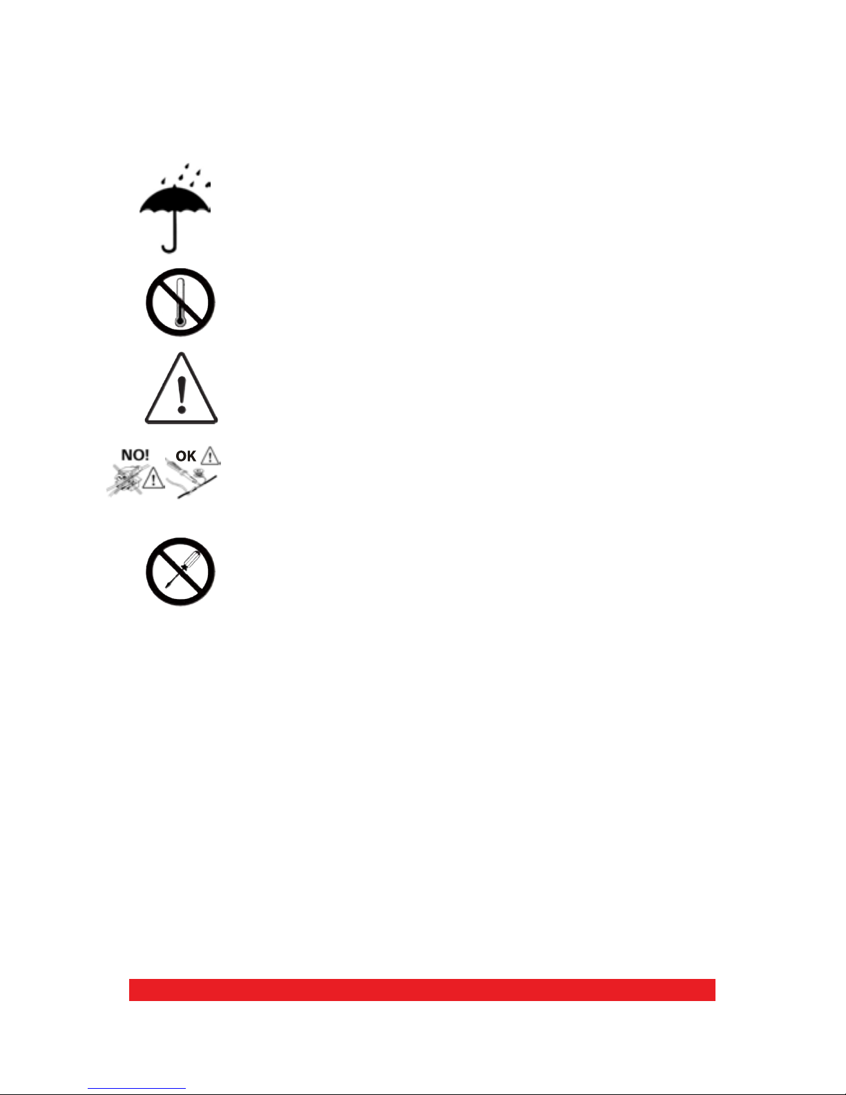
AVVERTENZE
CONTENUTO DELLA CONFEZIONE
OK
- Installare in posizione verticale lontano da possibili inltrazioni
d'acqua.
- Installare lontano da eccessive fonti di calore (es. collettori di
scarico).
- Installare lontano dalla bobina d'accensione e passare il
cablaggio lontano dai cavi dell'alta tensione.
- Realizzare delle buone connessioni elettriche evitando l'uso dei
“rubacorrente”. Si tenga presente che la migliore connessione è la
saldatura debitamente isolata.
-Nonaprirepernessunmotivola scatoladelVariatore, soprattutto
con il motore in moto o il quadro inserito.
L'A.E.B. declina ogni responsabilità per danni a cose e persone
derivati dalla manomissione del propio dispositivo da parte
di personale non autorizzato.
All’interno della confezione è presente:
1) N°1 Istruzione di montaggio
2) N°1 Centralina
3) N°1 Cablaggio di collegamento
4) N°1 Connettore emergenza
5) N°1 Sacchetto accessori
6) N°1 Etichetta attenzione

4
1 2
ON
OBD Emulators & T.A.P.
Programming Software
Italiano
English
Français
Polski
Português
Español
CHIAVE
HARDWARE
CHIAVE
USB
COLLEGARE ALLA
PORTA PARALLELA
(LPT1) O USB DEL
COMPUTER
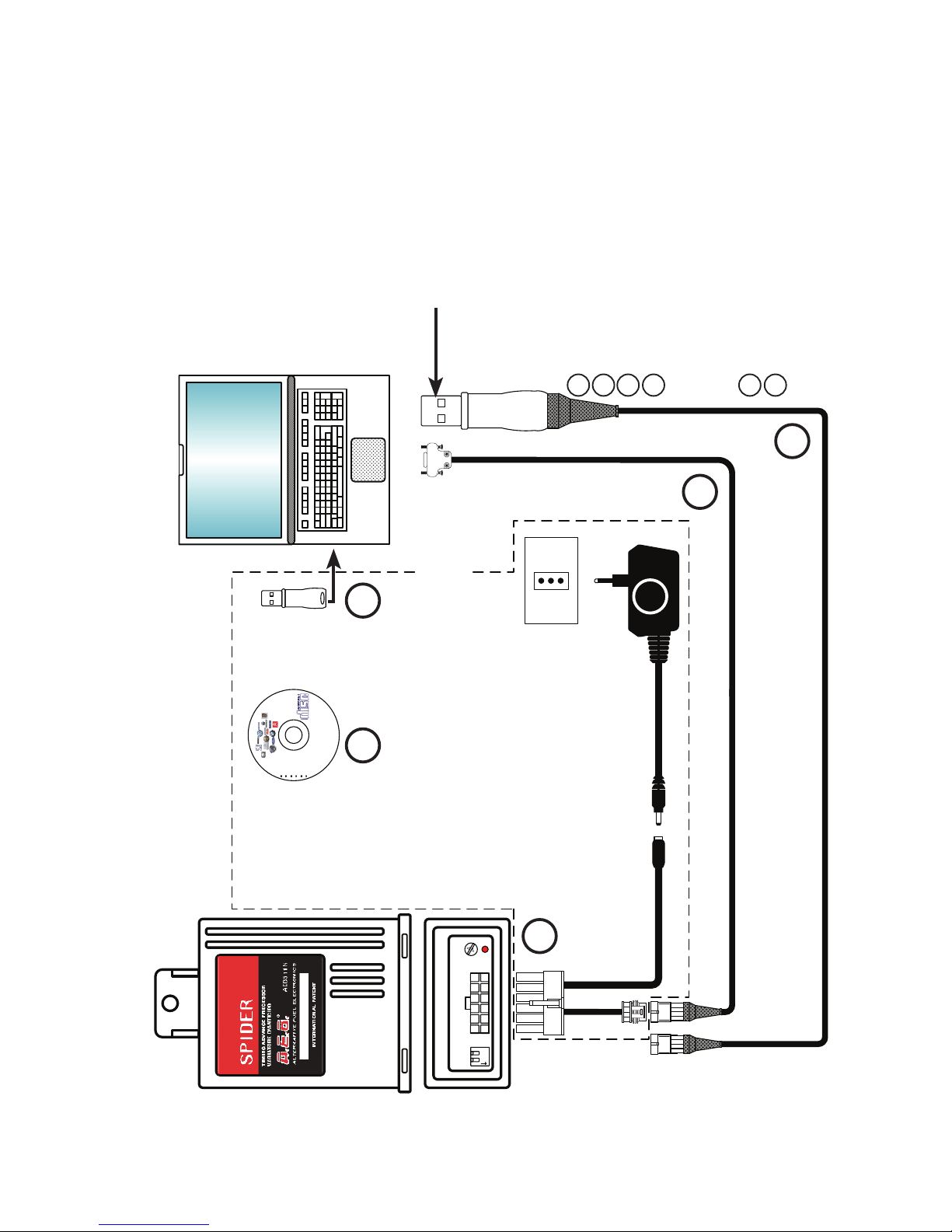
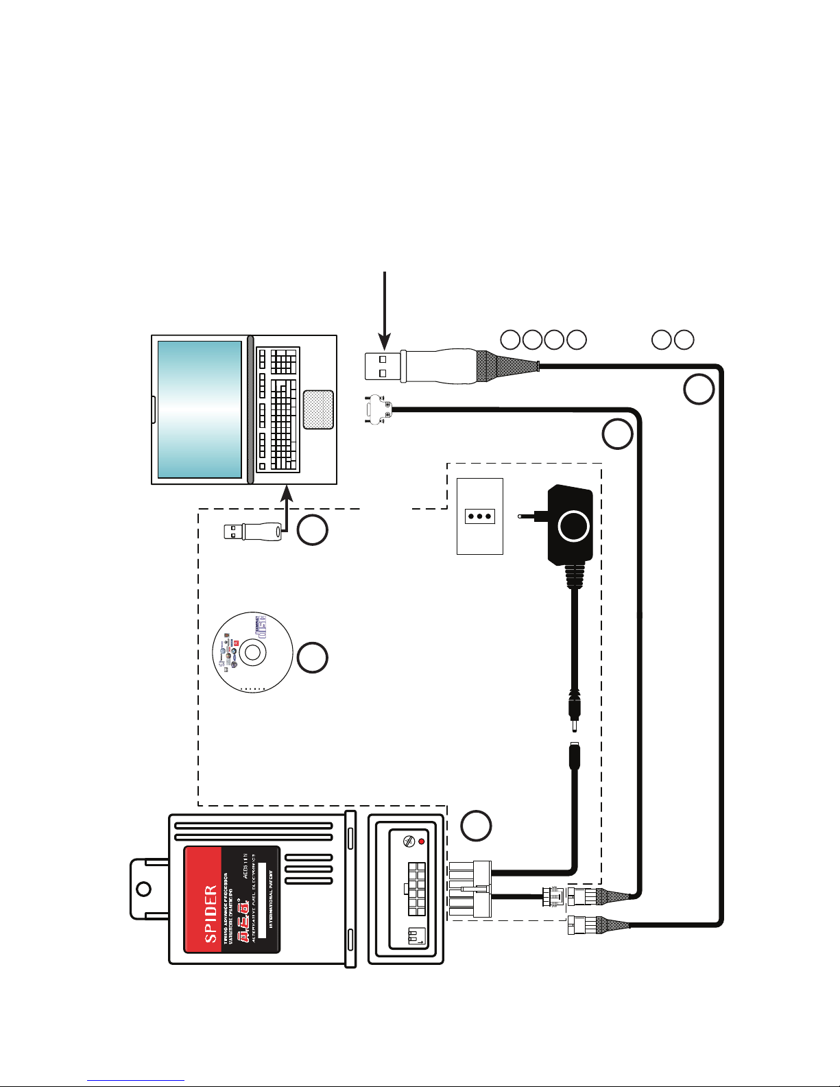
COMPOSIZIONE KIT AEB011
CAVO DI CONNESSIONE AL PC
ALIMENTATORE DI RETE
INTERFACCIA SERIALE
CHIAVE PARALLELA
CD INSTALLAZIONE SOFTWARE
COMPOSIZIONE KIT AEB011 USB
CAVO DI CONNESSIONE AL PC
ALIMENTATORE DI RETE
INTERFACCIA SERIALE
CHIAVE USB
CD INSTALLAZIONE SOFTWARE
COMPUTER CLIENTE
CON INSTALLATO APPOSITO
SOFTWARE PER
PROGRAMMAZIONE
VARIATORI ED EMULATORI OBD
(VERSIONE 3.3 O SUPERIORE)
COLLEGARE ALLA PRESA
SERIALE DEL COMPUTER
PRESA
220 V A.C.
INTERFACCIA
SERIALE
ALIMENTATORE
1
2
3
54
6
AGGIORNAMENTO FIRMWARE CON KIT AEB011/AEB011USB
N.B: Nel caso in cui il PC sia sprovvisto di porta seriale, è disponibile l’adapter
seriale/usb codice AEB020 US-SE
I
T
A
L
I
A
N
O
1
1
2
2
3
3
4
5
6
6
4
5
1 2
ON
12 3 4
OBD Emulators & T.A.P.
Programming Software
Italiano
English
Français
Polski
Português
Español
COLLEGARE ALLA
PORTA USB DEL
COMPUTER
COMPUTER CLIENTE
CON INSTALLATO APPOSITO
SOFTWARE PER
PROGRAMMAZIONE
VARIATORI ED EMULATORI OBD
(VERSIONE 3.3 O SUPERIORE)
PRESA
220 V A.C.
ALIMENTATORE
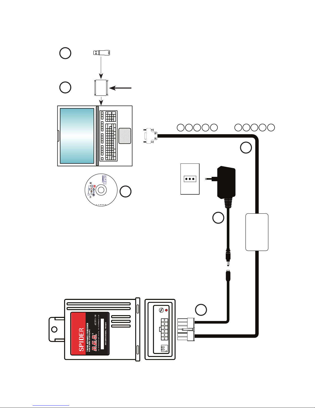
AGGIORNAMENTO FIRMWARE CON KIT AEB011N
1
2
5
6
CHIAVE
USB
CD INSTALLAZIONE
SOFTWARE
3 4
COLLEGARE ALLA PRESA
SERIALE DEL COMPUTER
N.B: Per la connessione del variatore al PC, non sono necessari entrambi i cavi (N°5 e N°6) in gura, ma solamente
uno dei due.
I
T
A
L
I
A
N
O
COMPOSIZIONE KIT AEB011N
CAVO DI CONNESSIONE AL PC
ALIMENTATORE DI RETE
CD INSTALLAZIONE SOFTWARE
CHIAVE USB
INTERFACCE
(NON COMPRESE NEL KIT)
INTERFACCIA SERIALE (AEB001NG)
INTERFACCIA USB (AEB001N USB)
1
2
3
4
5
6

6
AL CONNETTORE
DEL SENSORE DI PUNTO MORTO
SUPERIORE
(EFFETTO HALL)
VERDE *
ROSA
(INGRESSO SEGNALE)
ROSA-NERO
(USCITA SEGNALE)
VERDE-NERO *
POTENZIOMETRO
FARFALLA
* SE NON COLLEGATO ISOLARE FILO
SEGNALE
ROSSO
BLU-GIALLO
BLUNERO
MASSA
POSIZIONE GAS
DEL COMMUTATORE
+12 VOLT
SOTTOCHIAVE
FILO SEGNALE
CONNETTORE
DEL SENSORE
ALBERO A CAM
(EFFETTO HALL)
DA COLLEGARE SOLO
SU ALCUNE VETTURE
OPTIONAL
I
T
A
L
I
A
N
O
INSTALLAZIONE SENSORE PMS AD EFFETTO HALL E 1 SENSORE DI
FASE HALL

6
7
ITALIANO
PROGRAMMAZIONE
Il Variatore SPIDER è riprogrammabile, quindi un solo modello di Variatore si
potrà adattare a diversi modelli di vetture, aggiornando semplicemente il sof-
tware al suo interno, tramite un qualsiasi kit di programmazione:
AEB011 (con chiave hardware)•
AEB011USB (con chiave usb)•
AEB011 N.•
Si tenga presente che, in fase di collaudo, il Variatore è programmato con il
software 511N, quindi vericare sempre se questo è adatto alla vettura su cui
dovrà essere installato.
Il Variatore SPIDER Codice AEB511N, sostituisce il precedente modello MOUSE
in tutte le sue versioni.
Gli schemi elettrici d’installazione di ogni singola vettura invece, saranno di-
sponibili nel programma AEB On-Line; per chi ne fosse sprovvisto si dovrà ri-
volgere al suo rivenditore di ducia o al nostro servizio di assistenza tecnica.
L'elenco delle vetture su cui è possibile instal-
lare il variatore e la relativa programmazione è
disponibile sul sito internet AEB (www.aeb.it)
nella sezione prodotti/variatori/AEB511N.
LISTA AUTOVETTURE

8
ITALIANO
12
ON
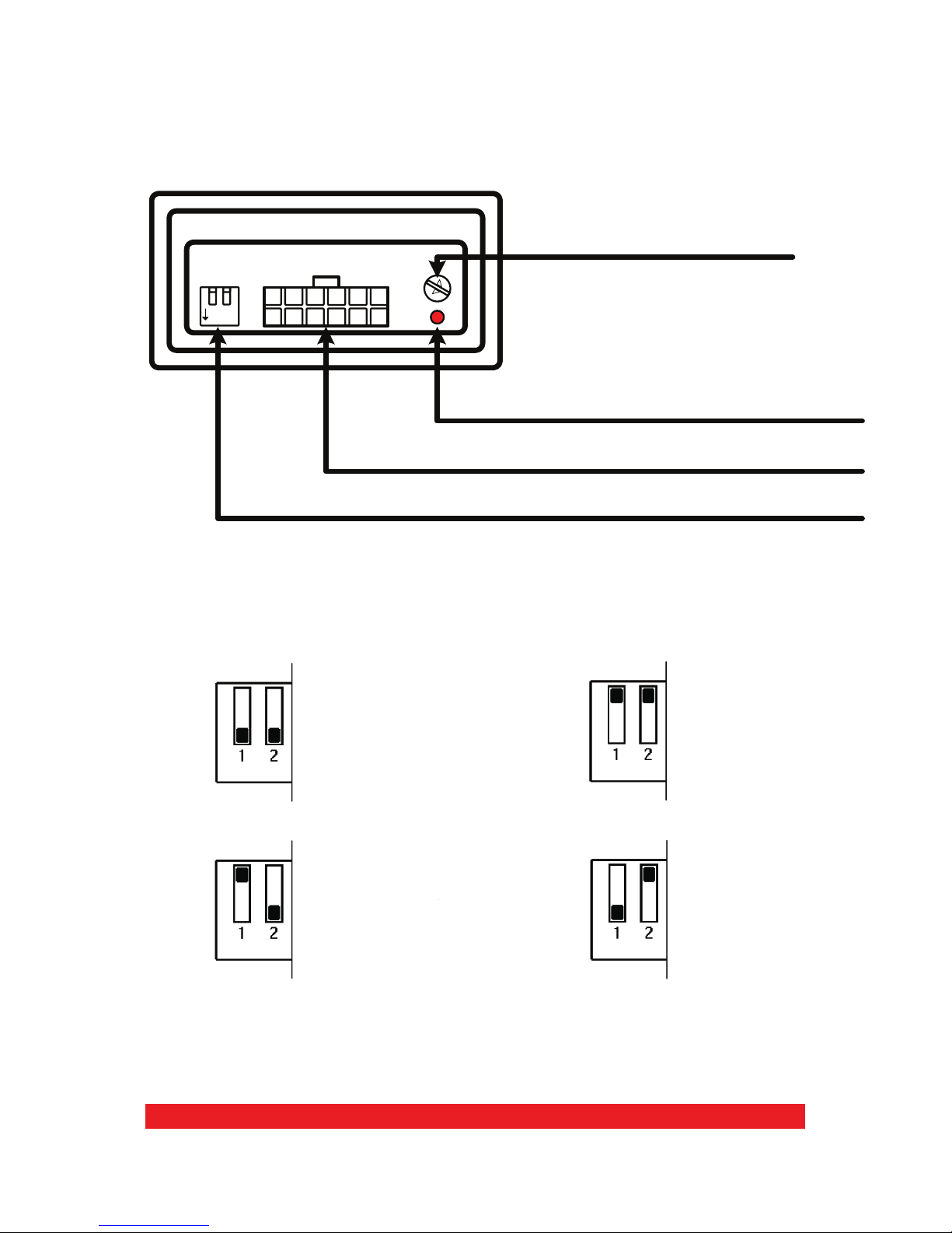
PROGRAMMAZIONE
REGOLAZIONE DELL’ ANTICIPO
Parte inferiore del variatore
MICROINTERRUTTORI PER LA PROGRAMMAZIONE
CONNETTORE PER IL COLLEGAMENTO E RIPROGRAMMAZIONE
LED ACCESO = ANTICIPO INSERITO
REGISTRO INTERVENTO ANTICIPO
PROGRAMMAZIONE GRADI DI ANTICIPO
15° di anticipo
9° di anticipo
12° di anticipo
6° di anticipo
9
ITALIANO
TARATURA INSERIMENTO ANTICIPO
Il segnale del potenziometro farfalla non è sempre uguale pertanto è prevista
una taratura del punto d’intervento.
La regolazione si eettua durante il funzionamento a GAS agendo sul registro
intervento anticipo nel seguente modo:
1) Vericare che il registro sia ruotato tutto in senso orario.
2) Con la vettura al minimo iniziare a ruotare il registro in senso antiorario n-
chè non si spegne il led ROSSO (anticipo disinserito).
3) Così regolato, accelerando, il led ROSSO sul Variatore si riaccende per poi
spegnersi quando si rilascia l’acceleratore.
PROGRAMMAZIONE
REGISTRO INTERVENTO ANTICIPO
LED ACCESO = ANTICIPO INSERITO
Come e quando disinserire l’anticipo in decelerazione e al minimo
Su alcune vetture è conveniente togliere l’anticipo in decelerazione e al mini-
mo, per evitare saltellii o funzionamenti irregolari.
D’altra parte l’anticipo serve immediatamente in fase di accelerazione, per mi-
gliorare prestazioni, consumi e ridurre al minimo il pericolo di ritorni di am-
ma. Con il Variatore SPIDER l’anticipo si può inserire o disinserire automatica-
mente collegando il lo BLU-GIALLO del Variatore al potenziometro farfalla.
NOTA: tralasciare l’operazione taratura inserimento anticipo nel caso non si
colleghi il lo BLU-GIALLO.

10
ITALIANO
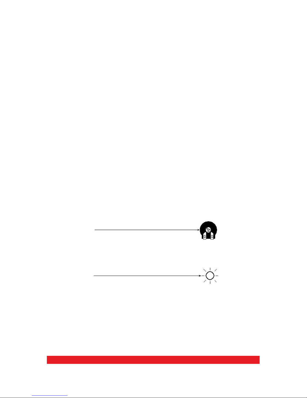
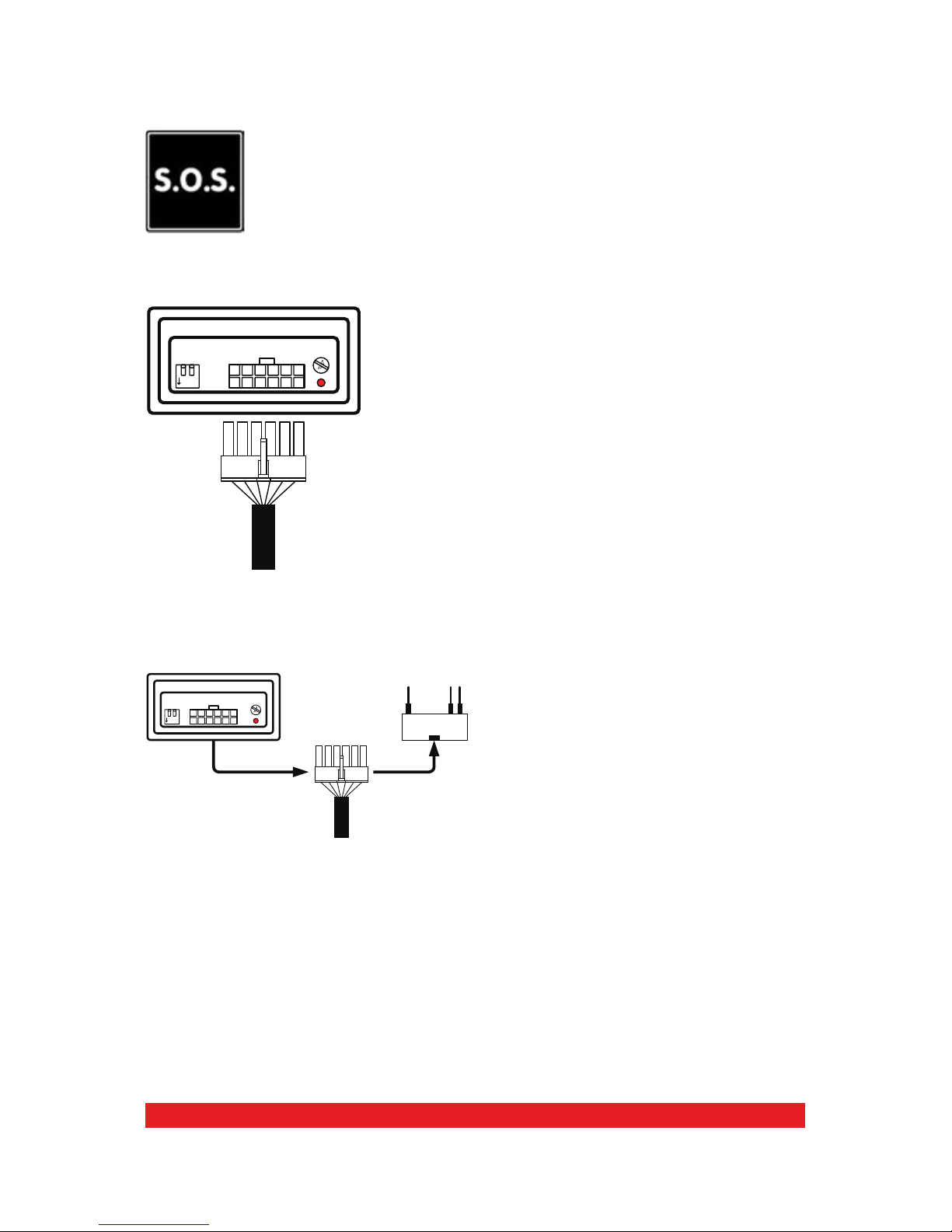
EMERGENZA
Avvisare il cliente che in caso di avaria il Variatore è dotato di con-
nettore di emergenza che lo esclude e ripristina il collegamento
originale.
PER ESCLUDERLO OPERARE COME SEGUE
FUNZIONAMENTO NORMALE
La spina del cablaggio è inserita nel
connettore del Variatore.
FUNZIONE EMERGENZA
Togliere il cablaggio dal connettore del
variatore ed inserirlo nel connettore di
EMERGENZA come da schema.
12
ON
12
ON
Il certicato di garanzia del prodotto è dispo-
nibile sul sito internet AEB (www.aeb.it) nella
sezione prodotti/variatori/AEB511N.
GARANZIA

11
ITALIANO
DATI TECNICI
Tensione di alimentazione 10 ÷ 14 Vcc
Regolazione anticipo 6°-9°-12°-15°
Ingombri scatola variatore
Altezza 105 mm
Profondità 35 mm
larghezza 80 mm
Ø foro di ssaggio 6 mm
Anticipo disinseribile in decelerazione tramite segnale T.P.S.
Programmazione di diversi tipi di ruota fonica in modo da poter
essere adattato a numerosi modelli di vetture.

12
ENGLISH
INDEX
ENGLISH
Warnings................................................................................................................................ 13
Contents Of The Package ................................................................................................ 13
Firmware Update With Aeb011/Aeb011usb Kit ...................................................... 14
Firmware Update With Aeb011n Kit............................................................................ 15
Installation Of Hall Eect Pms Sensor And 1 Hall Phase Sensors...................... 16
Programming.......................................................................................................................17
Cars List .................................................................................................................................17
Emergency............................................................................................................................20
Warranty ................................................................................................................................ 20
Technical Data .....................................................................................................................21
User Licence Agreement.................................................................................................. 33
13
ENGLISH
WARNINGS
CONTENTS OF THE PACKAGE
- Install vertically away from possible water leaks.
- Install away from excessive heat sources (e.g. exhaust mani-
folds).
- Install away from the ignition coils and route the wiring harness
away from high voltage wires.
- Make good electrical connections without using cable clamps.
Remember that the best connection is a duly insulated soldering.
- Do not open the timing advance processor casing for any rea-
son whatsoever, especially when the engine is running or the
panel is switched on.
A.E.B. shall not be held liable for damage to things or peo-
ple caused by unauthorised personnel tampering with the
device.
The package contains:
1) No.1 Assembly instruction manual
2) No.1 Control unit
3) No.1 Connection wiring harness
4) No.1 Emergency connector
5) No.1 Bag of accessories
6) No.1 Warning label
OK
14
1 2
ON
OBD Emulators & T.A.P.
Programming Software
Italiano
English
Français
Polski
Português
Español
HARDWARE
KEY USB KEY
CONNECT
TO THE COMPUTER
PARALLEL PORT (LPT1)
OR USB PORT.
COMPOSITION OF THE AEB011 KIT
PC CONNECTION CABLE
MAINS POWER SUPPLY
SERIAL INTERFACE
PARALLEL KEY
SOFTWARE INSTALLATION CD
COMPOSITION OF THE AEB011 USB KIT
PC CONNECTION CABLE
MAINS POWER SUPPLY
SERIAL INTERFACE
USB KEY
SOFTWARE INSTALLATION CD
CLIENT COMPUTER WITH
SPECIFIC SOFTWARE INSTALLED
FOR PROGRAMMING TIMING
ADVANCE PROCESSORS AND
OBD EMULATORS
(VERSION 3.3 OR LATER).
CONNECT TO THE
COMPUTER SERIAL PORT
220 V.A.C.
POWER
OUTLET.
SERIAL
INTERFACE
POWER SUPPLY
1
2
3
54
6
FIRMWARE UPDATE WITH AEB011/AEB011USB KIT
NOTE: If the PC does not have a serial port, a serial/USB adapter is available
(code AEB020 US-SE).
E
N
G
L
I
S
H
1
1
2
2
3
3
4
5
6
6
14
15
1 2
ON
12 3 4
OBD Emulators & T.A.P.
Programming Software
Italiano
English
Français
Polski
Português
Español
CONNECT TO THE
COMPUTER USB
PORT
CCLIENT COMPUTER
WITH SPECIFIC SOFTWARE
INSTALLED FOR
PROGRAMMING TIMING
ADVANCE PROCESSORS AND
OBD EMULATORS
(VERSION 3.3 OR LATER).
220 V.A.C.
POWER
OUTLET
POWER SUPPLY
FIRMWARE UPDATE WITH AEB011N KIT
1
2
5
6
USB KEY
SOFTWARE
INSTALLATION CD
3 4
CONNECT TO THE
COMPUTER SERIAL PORT
NOTE: To connect the timing advance processor to the PC, it is not necessary to use both the cables (NO.5 and NO.6)
illustrated in the gure, just one is enough.
E
N
G
L
I
S
H
COMPOSITION OF THE
AEB011N KIT
PC CONNECTION CABLE
MAINS POWER SUPPLY
SOFTWARE INSTALLATION CD
USB KEY
INTERFACES
(NOT INCLUDED IN THE KIT)
SERIAL INTERFACE (AEB001NG)
USB INTERFACE (AEB001N USB)
1
2
3
4
5
6

16
INSTALLATION OF HALL EFFECT PMS SENSOR AND 1 HALL
PHASE SENSORS
E
N
G
L
I
S
H
TO THE TOP DEAD CENTRE SENSOR
CONNECTOR
(HALL EFFECT)
GREEN *
BROWN
PINK
(SIGNAL INPUT)
PINK-BLACK
(SIGNAL OUTPUT)
GREEN-BLACK *
THROTTLE
POTENTIOMETER
* ISOLATE IF NOT CONNECTED
REVOLUTION
SIGNAL OUTPUT
FOR FEEDBACK
OR INJECTION
SIGNAL
WIRE
RED
BLUE-YELLOW
BLUEBLACK
GROUND
SWITCH SET ON GAS
+12 VOLT
SUBKEY
CAM SHAFT SENSOR
CONNECTOR SIGNAL
WIRE
(HALL EFFECT)
ONLY TO BE
CONNECTED ON
SOME VEHICLES
OPTIONAL

16
17
ENGLISH
PROGRAMMING
The SPIDER timing advance processor is reprogrammable; therefore, just one
timing advance processor model can be adapted to various vehicle models by
simply updating the Firmware using any programming kit.
AEB011 (with hardware key)•
AEB011USB (with USB key)•
AEB011 N•
Bear in mind that during the test phase, the timing advance processor is pro-
grammed with the 511N software, therefore always ensure that this is suitable
for the vehicle on which it has to be installed.
The SPIDER Timing Advance Processor Code AEB511N, replaces the previous
model MOUSE in all its versions.
The installation wiring diagrams of each vehicle will be available in the A.E.B.
On-Line program; if you do not have the A.E.B. On-Line program, please con-
sult your dealer or our technical assistance service.
The list of cars on which you can t the timing
advance processor and the relevant software
is available on the website AEB (www.aeb.
it) in the products section/timing advance
processors/AEB511N
CARS LIST
18
ENGLISH
12
ON
PROGRAMMING
TIMING ADVANCE ADJUSTMENT
Lower part of the timing advance processor
PROGRAMMING MICROSWITCHES
CONNECTION AND REPROGRAMMING CONNECTOR
LED ON = TIMING ADVANCE ENABLED
TIMING ADVANCE TRIP REGISTER
TIMING ADVANCE DEGREES PROGRAMMING
15° advance
9° advance
12° advance
6° advance

19
ENGLISH
TIMING ADVANCE ENABLING CALIBRATION PROCEDURE
The throttle potentiometer signal is not always the same; therefore, the trip
point needs to be calibrated.
Adjustment is carried out during GAS function by acting on the timing ad-
vance trip register as follows:
1) Ensure the register is turned completely clockwise.
2) While the vehicle is idling, turn the register anticlockwise until the RED LED
switches o (timing advance disabled).
3) With this adjustment, during acceleration, the RED LED on the timing advance
processor lights up and then switches o when the accelerator is released.
PROGRAMMING
How and when to disable the timing advance during deceleration and
when idling
On some vehicles it is convenient to disable the timing advance during decel-
eration and when idling to avoid jumps or irregular function.
On the other hand, the timing advance is required immediately during ac-
celeration to improve performance, consumption and to minimise the risk of
backring.With the SPIDER timing advance processor, the timing advance can
be enabled or disabled automatically connecting the BLUE-YELLOW wire on
the timing advance processor to the throttle potentiometer.
NOTE: do not carry out the timing advance enabling calibration procedure if
the BLUE-YELLOW wire is not connected.
TIMING ADVANCE TRIP REGISTER
LED ON = TIMING ADVANCE ENABLED
20
ENGLISH
EMERGENCY
Warn the customer that in case of a malfunction, the timing ad-
vance processor is equipped with an emergency connector that
cuts it o and restores the original connection.
TO CUT OFF, PROCEED AS FOLLOWS
NORMAL FUNCTION
The wiring harness outlet is inserted
in the timing advance processor con-
nector.
EMERGENCY FUNCTION
Remove the wiring harness from the
timing advance connector and insert
it in the EMERGENCY connector as
indicated in the diagram.
12
ON
12
ON
The warranty certicate is available on the
website AEB (www.aeb.it) in the products sec-
tion/timing advance processors/AEB511N
WARRANTY
This manual suits for next models
1
Table of contents
Languages:
Other AEB Automobile Accessories manuals


