AEB 2010 User manual
AEB Alternative Fuel Electronics
via dell’industria 20 42025 - Cavriago - Italy
ph. +39 0522 494401 - fax. +39 0522 494410
technical assistance
ph. +39 0522 494414 - fax. +39 0522 494410
a division of
INJECTION CONTROL UNIT
10 CYLINDER
QUICK-START INSTALLATION

Isaeb2010-1 Rev. 061010-1 3-23
Il presente documento non può essere riprodotto né portato a conoscenza di terzi senza autorizzazione della ditta Aeb S.p.A.
This document may not be reproduced or made known to any third party without permission of the company Aeb S.p.A.
Isaeb2010-1 Rev. 061010-1 4-23
Il presente documento non può essere riprodotto né portato a conoscenza di terzi senza autorizzazione della ditta Aeb S.p.A.
This document may not be reproduced or made known to any third party without permission of the company Aeb S.p.A.
Italiano
Avvertenze generali 5
Schema posizionamento MAP 6
Schema di montaggio per 10 cilindri 7
Schema di collegamento dei li stacca iniettori 9
Funzionamento del commutatore 10
English
General information 11
MAP positioning diagram 12
10 cylinders wiring diagram 13
Cut injectorn wiring diagram 15
Change-over switch operation 16
Español
Advertencias generales 17
Esquema de posicionamiento MAP 18
Esquema de montaje para 10 cilindros 19
Esquema de conexión de los hilos da interrupción injectores 21
Funcionamiento del conmutador 22
INDICE/INDEX/INDICE
Isaeb2010-1 Rev. 061010-1
5-23
Il presente documento non può essere riprodotto né portato a conoscenza di terzi senza autorizzazione della ditta Aeb S.p.A.
This document may not be reproduced or made known to any third party without permission of the company Aeb S.p.A.
Isaeb2010-1 Rev. 061010-1
6-23
Il presente documento non può essere riprodotto né portato a conoscenza di terzi senza autorizzazione della ditta Aeb S.p.A.
This document may not be reproduced or made known to any third party without permission of the company Aeb S.p.A.
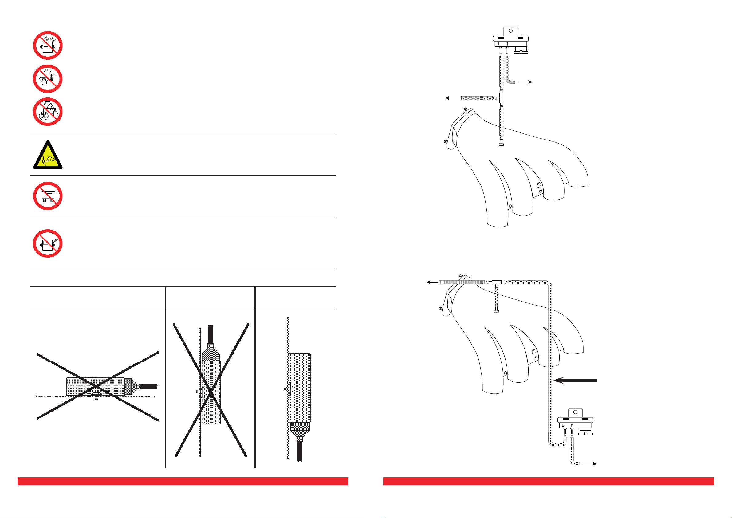
AVVERTENZE GENERALI ITALIANO
- LONTANO da possibili.
- LONTANO da(esempio collettori di scarico).
- LONTANO dai .
Fare delle buone connessioni elettriche evitando l’uso dei “RUBACORRENTE”.
Si tenga presente che la migliore connessione elettrica è la saldatura
debitamente isolata.
Avvisare il cliente che in caso di rottura del fusibile dell’impianto a GAS, il Si-
stema ripristina i collegamenti dei dispostivi a cui è collegato. Si sconsiglia
vivamente di sostituire il fusibile con un’altro di amperaggio maggiore, cio’ puo’
provocare danni irreparabili.
Non aprire per nessun motivo la scatola della Centralina soprattutto con il motore in
moto o il quadro inserito, onde evitare danni irreparabili.
Aeb declina ogni responsabilità per danni a cose e persone derivati dalla ma-
nomissione del proprio dispositivo da parte di personale non autorizzato con la
conseguente perdita di GARANZIA.
INSTALLAZIONE
INSTALLAZIONE
ERRATA
INSTALLAZIONE
ERRATA
NO
IL SENSORE
da riduttore
Sensore di pressioe
PressureV
PressureV
OK
Sensore di pressione
da riduttore
SENSORE IN ALTO
olle
tt
o
ri
di
a
spi
ra
zi
on
e
olle
tt
o
ri
di
a
spi
ra
zi
on
e
SCHEMA DI POSIZIONAMENTO MAP ITALIANO
7-23
8-23
PREDISPOSIZIONE
SONDA LAMBDA
BANCATA 1
SENSORI STANDARD A.E.B.
SENSORI STANDARD A.E.B.
TIPO 1050
SENSORI STANDARD
0÷90 OHM
MASSA
BIANCO
VERDE
MASSA
BIANCO
VERDE ISOLARE
MASSA
BIANCO
VERDE
BIANCO
VERDE
RIFERIMENTO
GIRI MOTORE
COMMUTATORE
VIOLA
GRIGIO PREDISPOSIZIONE
SONDA LAMBDA
BANCATA 2
VIOLA-NERO
GRIGIO-NERO
GIALLO-NERO
GIALLO
NERO
ANELLO ROSSO
CABLAGGIO STACCA
INIETTORI
CABLAGGIO STACCA
INIETTORI
CONNETTORE
NERO
VERDE
VERDE-NERO
ROSSO
ROSSO-NERO
BLU
GIALLO
GIALLO-NERO
BLU-NERO
ROSA
ROSA-NERO
BIANCO-ROSSO
VERDE
VERDE-NERO
ROSSO
ROSSO-NERO
BLU
GIALLO
GIALLO-NERO
BLU-NERO
ROSA
ROSA-NERO
BIANCO-ROSSO
NON COLLEGARE
NON COLLEGARE
MASSA
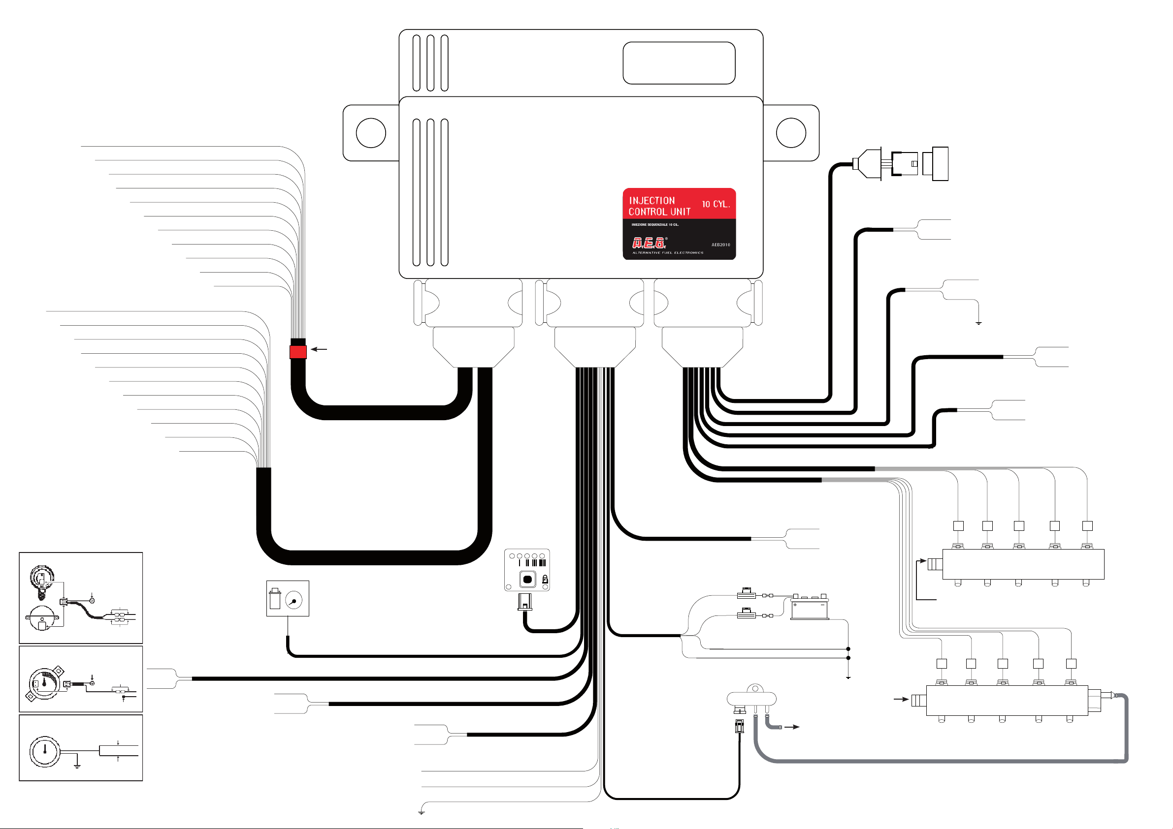
ATTENZIONE
SCHEMA DI MONTAGGIO 10 CILINDRI ITALIANO
MARRONE
G
R
RPM
....
AD
E
G
I
L
DCB A
E
F
G F
H
L I
MASSA
NERO
NERO
VERDE
VERDE-NERO
ARANCIO
NERO
AL SENSORE
TEMPERATURA
RIDUTTORE
ARANCIO-NERO
NERO
AL SENSORE
TEMPERATURA
GAS
BLU
NERO
INGRESSO GAS
PRESA PER
INTERFACCIA SERIALE
MISURATORE
DI PRESSIONE
AEB 025
AL COLLETTORE
D’ASPIRAZIONE
FUSIBILE (MAX 10A)
BLU-BIANCO
NERO
MULTIVALVOLA
O
ELETTROVALVOLE POSTERIORI
ELETTROVALVOLA
RIDUTTORE ED EVENTUALI
UTILIZZI GAS
R
O
S
S
O
-
N
E
R
O
R
OS
S
O-NERO
INGRESSO GAS
MASSA
CONNETTORE
NERO
CONNETTORE
GRIGIO
NON
COLLEGARE
Isaeb2010-1 Rev. 061010-1 9-23
Il presente documento non può essere riprodotto né portato a conoscenza di terzi senza autorizzazione della ditta Aeb S.p.A.
This document may not be reproduced or made known to any third party without permission of the company Aeb S.p.A.
Isaeb2010-1 Rev. 061010-1
10-23
Il presente documento non può essere riprodotto né portato a conoscenza di terzi senza autorizzazione della ditta Aeb S.p.A.
This document may not be reproduced or made known to any third party without permission of the company Aeb S.p.A.
Descrizione del funzionamento
Il commutatore che viene fornito nel kit dispone di un pulsante, 7 led luminosi e un cicalino in-
terno.
Serve per selezionare il tipo di alimentazione, Benzina o Gas; premendolo si passerà da un tipo di
carburante all’altro.
la centralina è predisposta per l’avviamento a Benzina
ed il passaggio automatico a GAS.
funzionamento a GAS.
Indicatore di livello carburante; led ROSSO riserva, mentre i 4 led VERDI forniscono l’indica-
zione del livello carburante (1/4, 2/4, 3/4, 4/4). L’indicatore è acceso solo quando è selezionata la
modalità gas.
funzionamento a BENZINA.
la centralina è predisposta per l’avviamento a Benzina
ed il passaggio automatico a GAS.
Quando il commutatore è in riserva e la pressione del gas scende al di sotto di un valore prestabilito,
la centralina commuta automaticamente a benzina. Questo viene fatto per evitare che il motore possa
girare con una carburazione troppo magra danneggiando così il catalizzatore. Prima di ripassare la
vettura a Gas effettuare il rifornimento. viene
segnalato dal commutatore con l’accensione del led GIALLO funzionamento a Benzina, l’accensione
alternata del LED ROSSO indicatore e dei 4 LED VERDI e con l’avviso acustico del cicalino interno. Per
riportare il commutatore al funzionamento normale è necessario premere una volta il PULSANTE,
rimarrà acceso il LED GIALLO per indicare che la vettura sta funzionando a Benzina ed il cicalino
smette di suonare.
Nel caso che la vettura sia impossibilitata ad avviarsi a benzina (es. problemi alla pompa benzina
ecc.), è possibile avviarla direttamente a GAS, per fare questo effettuare le seguenti operazioni:
• inserire il quadro e premere il pulsante per portare il commutatore in funzionamento a Gas;
• disinserire il quadro;
• inserire il quadro e tenere premuto il pulsante (circa 5 secondi) no a quando il LED VERDE smette
di lampeggiare;
• a questo punto effettuare l’avviamento del motore senza spegnere il quadro, la vettura partirà
direttamente a GAS;
• ogni volta che si spegnerà la vettura sarà necessario ripetere l’operazione per poterla riavviare in
EMERGENZA.
ATTENZIONE!
4 LED VERDI
LIVELLO
CARBURANTE
LED GIALLO
FUNZIONAMENTO
A BENZINA
LED ROSSO
RISERVA
PULSANTE
LED VERDE
FUNZIONAMENTO
A GAS
SEGNALAZIONE
DIAGNOSI
FUNZIONAMENTO DEL COMMUTATORE ITALIANO
INIETTORI BENZINA
COLLETTORI
D’ASPIRAZIONE
INIETTORI GAS
CONNETTORE
DEL CABLAGGIO
STACCA INIETTORI
INIETTORI GAS
BLU-NERO
BLU
ROSSO-NERO
ROSSO
VERDE-NERO
VERDE
GIALLO-NERO
GIALLO
CONNETTORE
DEL CABLAGGIO
STACCA INIETTORI
BLU-NERO
BLU
ROSSO-NERO
ROSSO
VERDE-NERO
VERDE
GIALLO-NERO
GIALLO
BIANCO-ROSSO
+12 VOLT
SOTTO CHIAVE
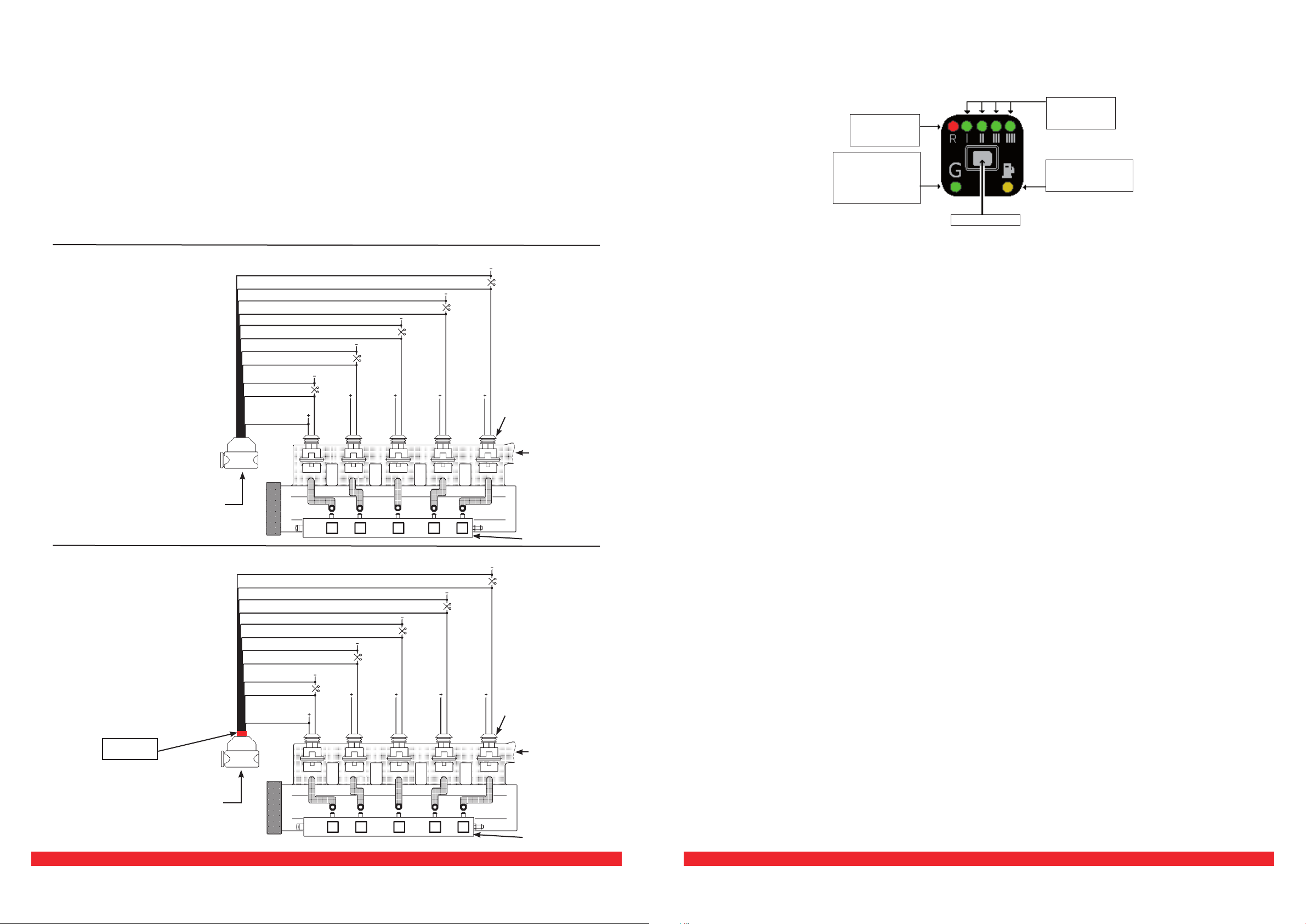
ATTENZIONE!
Rispettare la sequenza dei
collegamenti, i li e
devono
essere in corrispondenza
dell’iniettore gas marcato A,
gli altri di seguito come in
gura.
INIETTORI.
Schema di collegamento cablaggio stacca iniettori con anello rosso
Schema di collegamento cablaggio stacca iniettori senza anello rosso
ROSA-NERO
ROSA
ATTENZIONE!
Rispettare la sequenza dei
collegamenti, i li e
devono
essere in corrispondenza
dell’iniettore gas marcato F,
gli altri di seguito come in
gura.
INIETTORI.
COLLETTORI
D’ASPIRAZIONE
INIETTORI BENZINA
ROSA-NERO
ROSA
BIANCO-ROSSO
+12 VOLT
SOTTO CHIAVE
A
DE
F
G
I
L
BANDELLA
ROSSA
SCHEMA DI COLEGAMENTO DEI FILI STACCA INIETTORI ITALIANO
- da collegarsi all’iniettore gas in corrispondenza dell’iniettore benzina staccato con
li BLU E BLU-NERO dello stacca iniettori.
- da collegarsi all’iniettore gas in corrispondenza dell’iniettore benzina staccato con
li ROSSO E ROSSO-NERO dello stacca iniettori.
- da collegarsi all’iniettore gas in corrispondenza dell’iniettore benzina staccato con
li VERDE E VERDE-NERO dello stacca iniettori.
- da collegarsi all’iniettore gas in corrispondenza dell’iniettore benzina staccato con
li GIALLO E GIALLO-NERO dello stacca iniettori.
- da collegarsi all’iniettore gas in corrispondenza dell’iniettore benzina staccato con
li ROSA E ROSA-NERO dello stacca iniettori.
Tagliare i li negativi degli iniettori benzina, seguendo l’ordine riportato in gura.
È molto importante il verso di collegamento, i li rigati NERI vanno verso la centralina d’iniezione benzina, gli
altri verso gli iniettori.
Il lo va collegato a uno qualsiasi dei positivi iniettori.
L’iniettore GAS espreso tra parentesi, va riferito allo stacca-iniettori con la bandella rossa
Isaeb2010-1 Rev. 061010-1 11-23
Il presente documento non può essere riprodotto né portato a conoscenza di terzi senza autorizzazione della ditta Aeb S.p.A.
This document may not be reproduced or made known to any third party without permission of the company Aeb S.p.A.
Isaeb2010-1 Rev. 061010-1
12-23
Il presente documento non può essere riprodotto né portato a conoscenza di terzi senza autorizzazione della ditta Aeb S.p.A.
This document may not be reproduced or made known to any third party without permission of the company Aeb S.p.A.
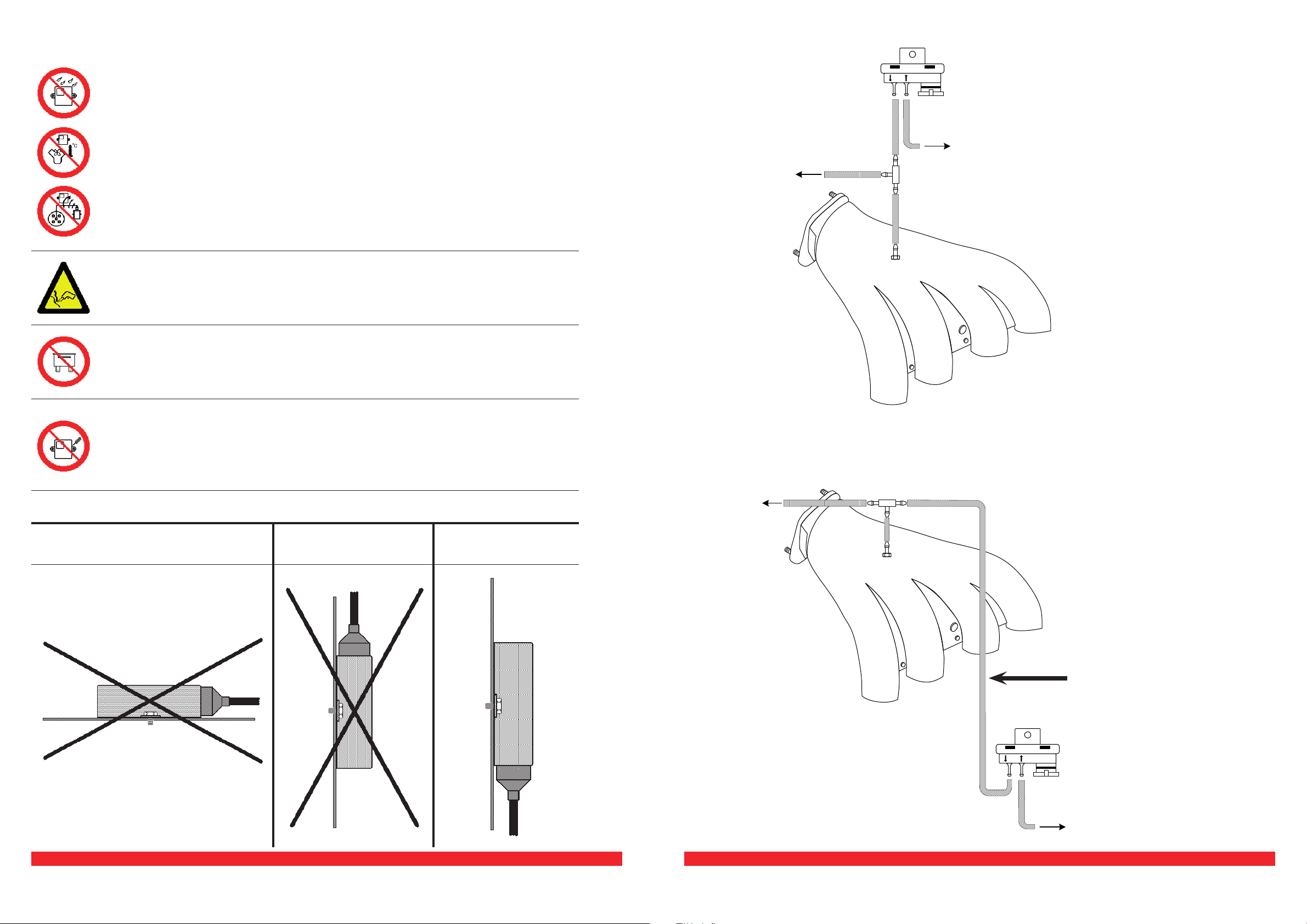
NO
Regulator
compensation
PressureV
PressureV
OK
Regulator
compensation
I
n
ta
k
e
ma
nif
o
ld
I
n
ta
k
e
ma
nif
o
ld
MAP POSITIONING DIAGRAM ENGLISH
- FAR from any
- FAR from(such as exhaust manifolds).
- FAR from
Create efcient electrical connections without using any “POWER TAPS”.
Advise the customer that if the GAS system fuse burns, the connections of the
devices to which it is connected will be restored. It is strongly recommended
not to replace the fuse with another one with a higher amperage rating since
it may cause irreparable damage.
Do not open the Control Unit box for any reason, especially when the engine is running
or the key is in the ignition, to avoid irreparable damage.
Aeb will not be held responsible for damage to property or injuries to persons
if unauthorised personnel tamper with its devices; such tampering will also
INSTALLATION
INSTALLATION
INSTALLATION
GENERAL INFORMATION ENGLISH
13-23
14-23
BANK 1 OXYGEN
SENSOR FITTING
A.E.B. STANDARD SENSORS
A.E.B. STANDARD SENSORS
TYPE 1050
0÷90 OHM STANDARD
SENSORS
GROUND
WHITE
GREEN
GROUND
WHITE
GREEN DO NOT CONNECT
GROUND
WHITW
GREEN
WHITE
GREEN
ENGINE RPM
REFERENCE
CHANGE OVER
SWITCH
VIOLET
GREY BANK 2 OXYGEN
SENSOR FITTING
VIOLET-BLACK
GREY-BLACK
YELLOW-BLACK
YELLOW
BLACK
RED RING
CUT INJECTORS
WIRING
CUT INJECTORS
WIRING
BLACK
CONNECTOR
GREEN
GREEN-BLACK
RED
RED-BLACK
BLUE
YELLOW
YELLOW-BLACK
BLUE-BLACK
ROSE
ROSE-BLACK
WHITE-RED
GREEN
GREEN-BLACK
RED
RED-BLACK
BLUE
YELLOW
YELLOW-BLACK
BLUE-BLACK
ROSE
ROSE-BLACK
WHITE-RED
DO NOT CONNECT
DO NOT CONNECT
GROUND
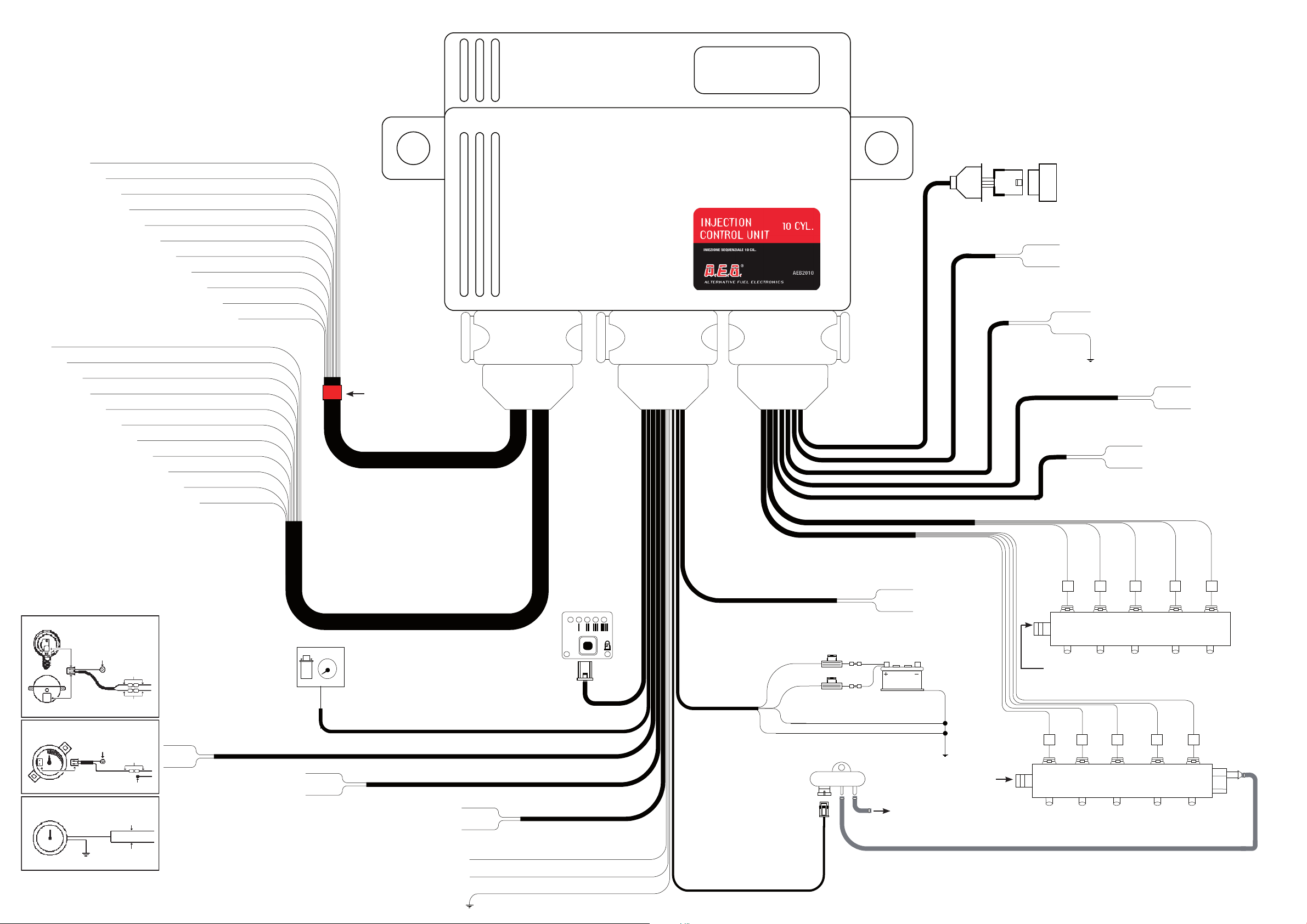
10 CYLINDERS WIRING DIAGRAM ENGLISH
BROWN
G
R
RPM
....
AD
E
G
I
L
DCB A
E
F
G F
H
L I
GROUND
BLACK
BLACK
GREEN
GREEN-BLACK
ORANGE
BLACK
TO THE
CONVERTER
TEMPERATURE
SENSOR
ORANGE-BLACK
BLACK
TO THE GAS
TEMPERATURE
SENSOR
BLUE
BLACK
GAS INLET
SERIAL INTERFACE
SOCKET
PRESSURE
GAUGE
AEB 025
TO THE SUCTION
MANIFOLD
FUSE (MAX 10A)
BLUE-WHITE
BLACK
MULTIVALVE CONVERTER
OR
POSTERIOR GAS SOLENOIDS
PRESSURE REGULATOR SOLENOID
VALVE AND GAS PORTS
R
E
D
-
B
L
A
C
K
R
ED
-
B
LACK
GAS INLET
GROUND
GREY
CONNECTOR
DO NOT
CONNECT
BLACK
CONNECTOR
Isaeb2010-1 Rev. 061010-1 15-23
Il presente documento non può essere riprodotto né portato a conoscenza di terzi senza autorizzazione della ditta Aeb S.p.A.
This document may not be reproduced or made known to any third party without permission of the company Aeb S.p.A.
Isaeb2010-1 Rev. 061010-1
16-23
Il presente documento non può essere riprodotto né portato a conoscenza di terzi senza autorizzazione della ditta Aeb S.p.A.
This document may not be reproduced or made known to any third party without permission of the company Aeb S.p.A.
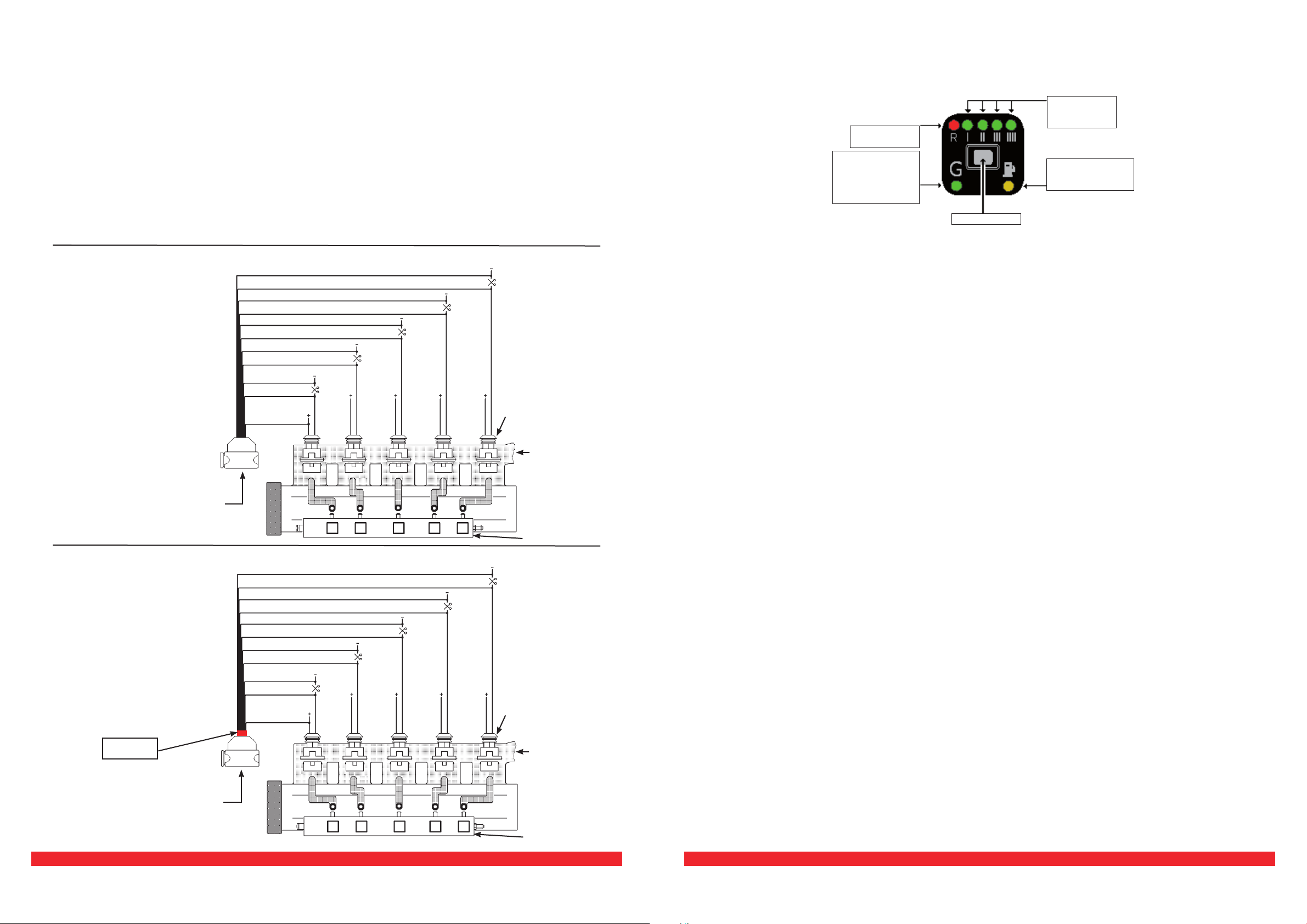
Follow the sequence of con-
nections. The and
wires must be
positioned at the gas injector
marked A. The others must
be connected as indicated in
the gure.
PETROL INJECTORS
SUCTION
MANIFOLDS
GAS INJECTORS
CUT INJECTOR
WIRING
CONNECTOR
GAS INJECTORS
BLUE-BLACK
BLUE
RED-BLACK
RED
GREEN-BLACK
GREEN
YELLOW-BLACK
YELLOW
CUT INJECTOR
WIRING
CONNECTOR
BLUE-BLACK
BLUE
RED-BLACK
RED
GREEN-BLACK
GREEN
YELLOW-BLACK
YELLOW
WHITE-RED
+12 VOLT WITH
IGNITION KEY
ROSE-BLACK
ROSE
SUCTION
MANIFOLDS
PETROL INJECTORS
ROSE-BLACK
ROSE
WHITE-RED
+12 VOLT WITH
IGNITION KEY
A
DE
F
G
I
L
RED RING
Follow the sequence of con-
nections. The and
wires must be
positioned at the gas injector
marked F. The others must
be connected as indicated in
the gure.
CUT INJECTOR WIRING DESCRIPTION ENGLISH
- to connect to the gas injector at the interrupted petrol injector with the cut injector
BLUE AND BLUE-BLACK wires.
- to connect to the gas injector at the interrupted petrol injector with the cut injector
RED AND RED-BLACK wires.
- to connect to the gas injector at the interrupted petrol injector with the cut injector
GREEN AND GREEN-BLACK wires.
- to connect to the gas injector at the interrupted petrol injector with the cut injector
YELLOW AND YELLOW-BLACK wires.
- to connect to the gas injector at the interrupted petrol injector with the cut injector
ROSE AND ROSE-BLACK wires.
To install this type of wiring, cut the negative wires of the petrol injectors in the order indicated in the gure.
The connection direction is very important. The wires should be installed toward the petrol
injection control unit and the others toward the injectors.
The wire should be connected to any of the injector positives.
The injector gas expressed in brackets, should be reported to the cut-injectors with the red strip
Operating description
The changeover switch supplied with the kit has one button, 7 LEDs and an internal buzzer.
This is used to select either the petrol or the gas fuel supply. Press the button one time to switch to
gas and press it again to return to petrol.
the control unit is prepared to start with petrol and switch automatically to GAS.
Gas operation.
Fuel level indicator; reserve RED LED, while the 4 GREEN LEDS indicate the fuel level (1/4, 2/4,
3/4, 4/4). The indicator is illuminated only when the gas mode is selected.
PETROL operation.
the control unit is prepared to start with petrol and
switch automatically to Gas.
When the changeover switch indicates the fuel tank is in reserve and the gas pressure drops below a
set value, the control unit automatically switches over to gas. This prevents the engine from running
with an excessively lean carburetion, thus damaging the catalyser. Before returning to gas opera-
tion, ll up. The changeover switch signals the changeover to petrol due to low gas pressure by
activating the internal buzzer, illuminating the YELLOW petrol operation LED and by illuminating the
RED LED in an alternating pattern with the 4 GREEN LEDS. To make the changeover switch return to
normal operation press the BUTTON one time; the YELLOW LED will remain on to indicate that the
car is operating with petrol and the buzzer turns off.
If the car won’t start with petrol (e.g. problems with the petrol pump, etc.), it can be started directly
with GAS. To do this follow the instructions listed below:
• insert the ignition key and press the button to switch the changeover switch to gas operation;
• remove the key;
• insert the ignition key and keep pressing the button (about 5 seconds) until the GREEN LED stops
ashing;
• now, start the engine without turning off the ignition key; the car will start directly with GAS;
• each time the car engine is turned off, the operation will have to be repeated to start in the EMER-
GENCY condition.
when the ignition key is turned
4 GREEN
LEDS - FUEL
LEVEL
YELLOW LED -
PETROL
OPERATION
RED LED
– EMPTY TANK
RESERVE
BUTTON
GREEN LED -
GAS OPERATION
WITH
DIAGNOSTIC
SIGNAL
CHANGEOVER SWITCH OPERATION ENGLISH

Isaeb2010-1 Rev. 061010-1 17-23
Il presente documento non può essere riprodotto né portato a conoscenza di terzi senza autorizzazione della ditta Aeb S.p.A.
This document may not be reproduced or made known to any third party without permission of the company Aeb S.p.A.
Isaeb2010-1 Rev. 061010-1
18-23
Il presente documento non può essere riprodotto né portato a conoscenza di terzi senza autorizzazione della ditta Aeb S.p.A.
This document may not be reproduced or made known to any third party without permission of the company Aeb S.p.A.
de posibles
de(por ejemplo colectores de escape).
de los
Efectuar unas buenas conexiones eléctricas evitando el uso de “LADRONES”.
-
mente aislada.
Se desaconseja completamente sustituir el fusible por otro de mayor amperaje,
esto puede provocar daños irreparables.
No abrir por ningún motivo la caja de la Unidad de control, sobre todo con el motor en
marcha o el cuadro encendido, esto para evitar daños irreparables.
con consiguiente anulación de la GARANTIA
ADVERTICIAS GENERALES ESPAÑOL
NO
desde
reductor
Sensor de presión
PressureV
PressureV
OK
Sensor de presión
desde reductor
ole
ct
o
r
e
s
de
ad
m
is
ió
n
ole
ct
o
r
e
s
de
ad
m
is
ió
n
ESQUEMA DE POSICIONAMIENTO MAP ESPAÑOL

19-23
20-23
PREDISPOSICIÓN
SONDA LAMBDA
BANCADA 1
SENSORES ESTÁNDAR A.E.B.
SENSORES ESTÁNDAR A.E.B.
TIPO 1050
SENSORES ESTÁNDAR
0÷90 OHM
MASA
BLANCO
VERDE
MASABLANCO
VERDE NO CONECTAR
MASA
BLANCO
VERDE
BLANCO
VERDE
REFERENCIA
REVOLUCIONES
CONMUTADOR
VIOLETA
GRIS PREDISPOSICIÓN
SONDA LAMBDA
BANCADA 2
VIOLETA-NEGRO
GRIS-NEGRO
AMARILLO-NEGRO
AMARILLO
NEGRO
ANILLO ROJO
CABLEADO INTERRUMPE
INYECTORES
CABLEADO INTERRUMPE
INYECTORES
CONETADOR
NEGRO
VERDE
VERDE-NEGRO
ROJO
ROJO-NEGRO
AZUL
AMARILLO
AMARILLO-NEGRO
AZUL-NEGRO
ROSADO
ROSADO-NEGRO
BLANCO-ROJO
VERDE
VERDE-NEGRO
ROJO
ROJO-NEGRO
AZUL
AMARILLO
AMARILLO-NEGRO
AZUL-NEGRO
ROSADO
ROSADO-NEGRO
BLANCO-ROJO
NO CONECTAR
NO CONECTAR
MASA
ESQUEMA DE MONTAJE PARA 10 CILINDROS ESPAÑOL
MARRÓN
G
R
RPM
....
AD
E
G
I
L
DCB A
E
F
G F
H
L I
MASA
NEGRO
NEGRO
VERDE
VERDE-NEGRO
NARANJA
NEGRO
AL SENSOR
TEMPERATURA
REDUCTOR
NARANJA-NEGRO
NEGRO
AL SENSOR
TEMPERATURA
GAS
AZUL
NEGRO
ENTRADA GAS
TOMA PARA INTERFAZ
SERIE
MEDIDOR
DE PRESIÓN
AEB 025
AL COLECTOR
DE ADMISIÓN
FUSIBLE (MAX 10A)
AZUL-BLANCO
NEGRO
MULTIVÁLVULA
O
ELECTROVÁLVULAS POSTERIOR
ELECTROVÁLVULAS
REDUCTOR Y
UTILIZACIONES GAS
R
O
J
O
-
N
E
G
R
O
R
OJ
O
-
NEGRO
ENTRADA GAS
MASA
CONECTADOR
NEGRO
CONECTADOR
GRIS
NO
CONECTAR

Isaeb2010-1 Rev. 061010-1 21-23
Il presente documento non può essere riprodotto né portato a conoscenza di terzi senza autorizzazione della ditta Aeb S.p.A.
This document may not be reproduced or made known to any third party without permission of the company Aeb S.p.A.
Isaeb2010-1 Rev. 061010-1
22-23
Il presente documento non può essere riprodotto né portato a conoscenza di terzi senza autorizzazione della ditta Aeb S.p.A.
This document may not be reproduced or made known to any third party without permission of the company Aeb S.p.A.
Descripción del funcionamiento
El conmutador que viene incluido en el kit tiene un pulsador, 7 LEDs luminosos y un aviso acústico
interno.
Sirve para seleccionar el tipo de alimentación, Gasolina o Gas; presionándolo se pasa de un tipo de
carburante al otro.
la unidad de control está preparada para la puesta en marcha
con gasolina y el paso automático a GAS.
funcionamiento con GAS.
Indicador de nivel carburante; LED ROJO reserva, mientras que los 4 LEDs VERDES proporcionan
la indicación del nivel de carburante (1/4, 2/4, 3/4, 4/4). El indicador está encendido sólo cuando está
seleccionada la modalidad Gas.
funcionamiento con GASOLINA.
la unidad de control está preparada para la puesta
en marcha con Gasolina y el paso automático a GAS.
Cuando el conmutador está en reserva y la presión del gas desciende por debajo de un valor prede-
terminado, la unidad de control conmuta automáticamente a Gasolina. Esto se hace para evitar que el
motor pueda girar con una carburación demasiado pobre dañando de esta manera el catalizador.
Antes de pasar de nuevo al Gas es necesario efectuar el repostaje.
El paso a Gasolina por baja presión del Gas es señalado por el conmutador con el encendido del
LED AMARILLO de funcionamiento con Gasolina, el encendido alternado del LED ROJO indicador y de los
4 LEDs VERDES y con el aviso acústico del zumbador interno.
Para poner de nuevo el conmutador en la posición para el funcionamiento normal es necesario presionar
una vez el PULSADOR, quedará encendido el LED AMARILLO para indicar que el automóvil está funcio-
nando con Gasolina y el zumbador para de sonar.
En el caso de que el automóvil no se pueda poner en marcha utilizando la gasolina (por ej. por proble-
mas con la bomba de la gasolina etc.) es posible ponerlo en marcha directamente con GAS, para ello es
necesario efectuar las siguientes operaciones:
• encender el cuadro y presionar el pulsador para poner el conmutador en el funcionamiento con Gas;
• apagar el cuadro;
• encender el cuadro y mantener presionado el pulsador (aproximadamente 5 segundos) hasta que el
LED VERDE cesa de parpadear;
• entonces poner en marcha el motor sin apagar el cuadro, el automóvil se pone en marcha utilizando
directamente el GAS como carburante;
• cada vez que se apagar el cuadro será necesario repetir estas operaciones para poner en marcha el
automóvil en condiciones de EMERGENCIA.
se enciende el cuadro.
4 LEDs VERDES
NIVEL
CARBURANTE
LED AMARILLO
FUNCIONAMIENTO
CON GASOLINA
LED ROJO
RESERVA
PULSADOR
LED VERDE
FUNCIONAMIENTO
CON GAS
SEÑALIZACIÓN
DIAGNÓSTICO
FUNCIONAMIENTO DEL COMMUTADOR ESPAÑOL
Respetar la secuencia de las
conexiones, los hilos y
se deben
corresponder con el inyector
gas marcado A, los otros a con-
tinuación como en la gura.
INYECTORES GASOLINA
COLECTORES
DE ADMISIÓN
INYECTORES GAS
CONECTADOR
DEL CABLEADO
INTERRUMPE
INYECTORES
INYECTORES GAS
AZUL-NEGRO
AZUL
ROJO-NEGRO
ROJO
VERDE-NEGRO
VERDE
AMARILLO-NEGRO
AMARILLO
CONECTADOR
DEL CABLEADO
INTERRUMPE
INYECTORES
AZUL-NEGRO
AZUL
ROJO-NEGRO
ROJO
VERDE-NEGRO
VERDE
AMARILLO-NEGRO
AMARILLO
BLANCO-ROJO
+12 VOLTIOS
CONTACTO LLAVE
cableado interrumpe inyectores con anillo rojo
ROSADO-NEGRO
ROSADO
COLECTORES
DE ADMISIÓN
INYECTORES GASOLINA
ROSADO-NEGRO
ROSADO
BLANCO-ROJO
+12 VOLTIOS
CONTACTO LLAVE
A
DE
F
G
I
L
ANILLO
ROJO
Respetar la secuencia de las
conexiones, los hilos y
se deben
corresponder con el inyector
gas marcado F, los otros a con-
tinuación como en la gura.
ESQUEMA DE CONEXIÓN DE LOS HILOS DE INTERRUPCIÓN INYECTORES ESPAÑOL
- a conectar con el inyector gas en correspondencia con el inyector gasolina desconec-
tado con hilos AZUL Y AZUL-NEGRO del interrumpe inyectores.
- a conectar con el inyector gas en correspondencia con el inyector gasolina desconec-
tado con hilos ROJO Y ROJO-NEGRO del interrumpe inyectores.
- a conectar con el inyector gas en correspondencia con el inyector gasolina desconec-
tado con hilos VERDE Y VERDE-NEGRO del interrumpe inyectores.
- a conectar con el inyector gas en correspondencia con el inyector gasolina desconec-
tado con hilos AMARILLO Y AMARILLO-NEGRO del interrumpe inyectores.
- a conectar con el inyector gas en correspondencia con el inyector gasolina desconec-
tado con hilos ROSADO Y ROSADO-NEGRO del interrumpe inyectores.
Para instalar este cableado es preciso cortar los hilos negativos de los inyectores gasolina, siguiendo el orden
indicado en la gura.
Es muy importante la dirección de la conexión, los hilos rayados NEGROS van hacia la unidad de control de
inyección gasolina, los otros hacia los inyectores.
El cable se debe conectar con uno cualquiera de los positivos inyectores.
AZUL-NEGRO
cableado interrumpe inyectores sin anillo rojo

Isaeb2010-1 Rev. 061010-1 23-23
Il presente documento non può essere riprodotto né portato a conoscenza di terzi senza autorizzazione della ditta Aeb S.p.A.
This document may not be reproduced or made known to any third party without permission of the company Aeb S.p.A.
Isaeb2010-1 Rev. 061010-1 24-23
Il presente documento non può essere riprodotto né portato a conoscenza di terzi senza autorizzazione della ditta Aeb S.p.A.
This document may not be reproduced or made known to any third party without permission of the company Aeb S.p.A.
Leggere con attenzione le seguenti condizioni generali.
Si precisa che le seguenti condizioni si intendono integralmente conosciute ed accettate
al momento dell’utilizzo del prodotto.
Oggetto del contratto
A.E.B. s.r.l. conserva la proprietà sul software (d’ora d’innanzi denominato “PROGRAMMA”) conte-
nuto all’interno del prodotto A.E.B. da Voi acquistato.
Con la vendita del prodotto A.E.B. s.r.l. non cede alcun diritto sul PROGRAMMA ,ma solo la facoltà di
utilizzo quale utente nale dello stesso, secondo le modalità di cui alle presenti condizioni generali
e secondo le ulteriori condizioni e avvertenze presenti nel manuale d’uso.
A.E.B. s.r.l. è la sola titolare dei diritti di privativa sul PROGRAMMA, dei diritti morali e di utilizzazione
economica, ivi compresi il diritto di riproduzione, traduzione, adattamento, trasformazione, modi-
cazione e distribuzione, sotto qualsiasi forma e senza limitazione alcuna, compresa la vendita e la
locazione anche di sue copie e delle sue versioni modicate od aggiornate.
A.E.B. s.r.l. è, altresì, titolare del diritto di proprietà su tutti i codici oggetto e su tutti i codici sor-
gente del PROGRAMMA.
Tutte le tecniche, gli algoritmi e i procedimenti contenuti nel Programma e nella relativa documen-
tazione sono informazioni riservate di proprietà di A.E.B. s.r.l..
Il Licenziatario non potrà in alcun modo disporre dei codici oggetto e di codici sorgente, né farne og-
getto di licenza o consentirne l’elaborazione, o impegnarne od altrimenti trasferire o in qualsivoglia
altro modo rendere disponibile a terzi il PROGRAMMA sia a titolo oneroso che gratuito.
Il Licenziatario non potrà concedere in locazione o in leasing il PROGRAMMA o parte di esso.
Il Licenziatario non potrà riprodurre, tradurre, adattare, trasformare, modicare il PROGRAMMA o
qualsiasi parte in esso contenuta, né potrà incaricare terzi di eseguire tali attività.
Il Licenziatario non potrà copiare, nemmeno parzialmente, i manuali relativi al PROGRAMMA e
l’eventuale materiale aggiuntivo (diagrammi logici o di usso, ecc.) e non potrà consentirne l’uso a
terzi.
Il Licenziatario non potrà decodicare, decompilare, disassemblare, modicare o tradurre il PRO-
GRAMMA, salvo quanto espressamente previsto da norme inderogabili di legge.
Il PROGRAMMA è concesso in licenza d’uso quale prodotto unitario.
Le sue singole parti componenti non possono essere separate per l’utilizzo in ambienti di elaborazio-
ne distinti o da parte di soggetti diversi dal Licenziatario.
In nessun caso A.E.B. srl sarà ritenuto responsabile dei danni diretti ed indiretti (inclusi il danno
per perdita o mancato guadagno o risparmio, o interruzione dell’attività, perdita di informazioni o
dati) derivante da una non corretta installazione del software o da un suo utilizzo non conforme alle
indicazioni riportate nel manuale d’istruzione.
Dal momento di interruzione della licenza o dallo scioglimento, per qualsiasi ragione vericatosi, del
presente contratto, rimane fermo il divieto d’uso, duplicazione o manipolazione del PROGRAMMA; il
Licenziatario sarà altresì tenuto ad osservare l’obbligo di condenzialità per 5 anni dalla cessazione
del presente contratto.
Tutti i marchi registrati e non, come ogni segno distintivo o denominazione, apposto sul PROGRAM-
MA e sulla relativa documentazione, restano di proprietà di A.E.B. s.r.l. senza che dalla stipulazione
del presente contratto derivi al Licenziatario alcun diritto sui medesimi.
Terzi, collaboratori e dipendenti del Licenziatario
Il Licenziatario si obbliga a far sì che quanti (dipendenti, collaboratori, clienti, fornitori, agenti)
hanno accesso al PROGRAMMA si vincolino al rispetto di tutti gli impegni qui assunti dallo stesso
Licenziatario.
Resta inteso che il Licenziatario rimane responsabile per qualsiasi inadempimento ascrivibile a colo-
ro che hanno avuto accesso al PROGRAMMA.
Foro competente
Foro competente a conoscere delle controversie relative all’interpretazione ed applicazione del pre-
sente contratto è il foro di Reggio Emilia.
Legge applicabile
La legge applicabile al presente contratto è la legge italiana.
Per quanto non espressamente disciplinato troveranno applicazione le norme del codice civile ita-
liano.
La nullità di una o più condizioni contenute nella presente licenza d’uso non comporterà in principio
la nullità dell’intero contratto.
CONTRATTO DI LICENZA D’USO
Read the following general conditions carefully.
accepted them at the time of the software usage.
Scope of the agreement
A.E.B. s.r.l. retains ownership of the software (herein referred to as “PROGRAM”) required to use the
A.E.B. product you have purchased.
A.E.B. s.r.l. does not assign any rights to the PROGRAM through the sale of this product, but solely
the right of use as the end user of the said product, in accordance with the modalities described in
these general conditions and subject to further conditions and cautions given in the user manual.
A.E.B. s.r.l. is the sole holder of all copyright and other rights of the PROGRAM, the moral rights and
the rights of economic use, including the right of reproduction, translation, adaptation, transforma-
tion, modication and distribution, in any form and with no restrictions whatsoever, including the
sale and the lease of its copies and of modied or updated versions.
A.E.B. s.r.l. is also the holder of the intellectual property rights to all the object codes and to all the
source codes for the PROGRAM.
All the techniques, algorithms and procedures contained in the PROGRAM and in the associated do-
cumentation are considered condential and property of A.E.B. s.r.l.
The Licensee may not dispose in any way of the object codes or source codes, or include them as
part of a licence, or allow them to be processed, pledged or otherwise transferred, or in any way to
make the PROGRAM available to third parties whether for sale or for free.
The Licensee shall not hire or lease the PROGRAM or any part of it.
The Licensee may not reproduce, translate, adapt, transform, modify the PROGRAM or any part of
its contents, nor may it engage third parties to perform the said activities.
The Licensee may not copy, even in part, the manuals relating to the PROGRAM and any additional
material (logical diagrams or ow charts, etc.) and may not consent to their use by third parties.
The Licensee may not decodify, decompile, disassemble, modify or translate the PROGRAM, except
as expressly provided under mandatory statutory regulations.
This user licence is granted for the PROGRAM as a single product.
Its individual component parts may not be divided for use in separate processing environments or
by parties other than the Licensee.
Under no circumstances shall A.E.B. s.r.l. be liable for direct and indirect damage (including damage
through loss of earnings or savings, or interruptions to activities, loss of information or data) deri-
ving from the incorrect installation of the software or from any use that does not comply with the
indications given in the user manual.
Any interruption to the licence or the cancellation of this agreement, for whatever reason this oc-
curs, shall not detract from the prohibition to use, duplicate or tamper with the PROGRAM; the
Licensee will also undertake to observe the obligation of condentiality for 5 years after the date
when this agreement expires.
Trademark
All trademarks, whether registered or not, and all distinctive signs or names used to mark the PRO-
GRAM and the associated documentation shall remain the property of A.E.B. s.r.l. and the Licensee
shall derive no rights to the latter by entering into this agreement.
Third parties and the Licensee’s collaborators and employees
The Licensee undertakes to ensure that all persons (employees, collaborators, clients, suppliers,
agents) with access to the PROGRAM are bound to observe all the obligations assumed herein by
the Licensee.
It is hereby understood that the Licensee will be liable for any breach attributable to those indivi-
duals who have been given access to the PROGRAM.
The court with jurisdiction to settle any disputes concerning the construal and application of this
agreement will be the Court of Reggio Emilia.
Applicable law
This contract will be governed by Italian law.
In the event of any aspect not expressly provided for herein, reference will be made to the provi-
sions of the Italian Civil Code.
The nullity of one or more conditions of this user license will not, in principle, determine the nullity
of the entire agreement.
USER LICENCE AGREEMENT
Table of contents
Other AEB Automobile Accessories manuals


