--------------------------------------------------------------------------10/21------------------------------------------------------------------------------------
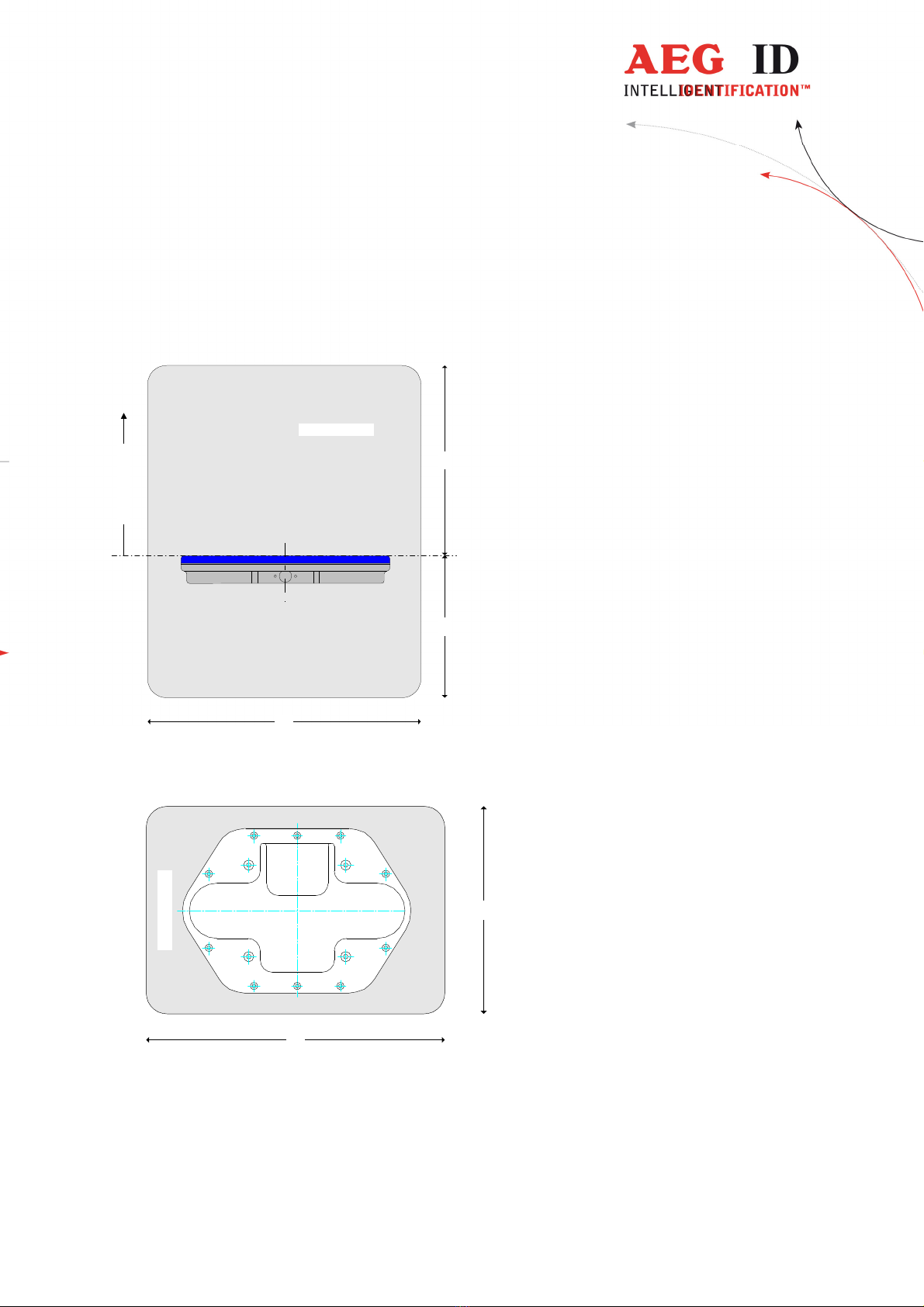
Case
Material Po an
Prote tion lass IP 65
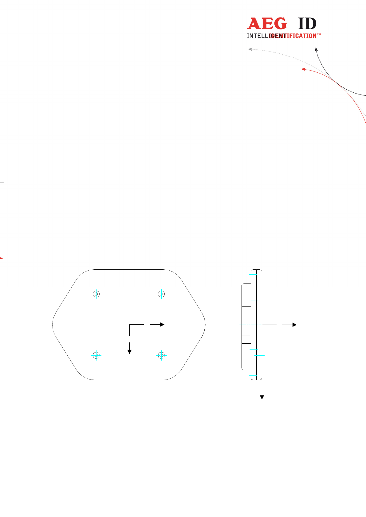
Dimensions 365 x 265 x 50mm
Weight approx. 2.0kg
Working temperature 0° C to +70°C
Storage temperature -20°C to +70°C
Maximal humidity 95% at +50°C (non- ondensing)
Electric requirements
Supply voltage 12V ± 0.3V (Id 1000495, 1000496)
24V ± 0.3V (Id 1002492, 1003745, 1004083)
Che k the identifi ation plate
Maximal urrent approx. 1.2A for 12V devi e
approx.. 1A for 24V devi e
Current onsumption in standby mode (antenna off) approx. 0.15A
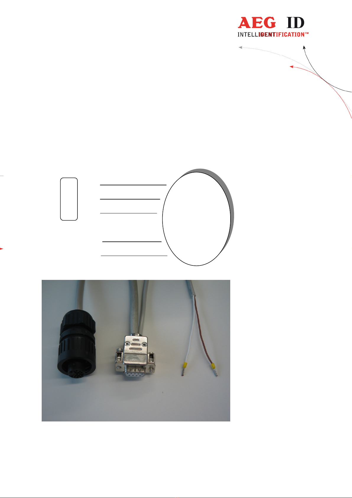
Interfa e RS 232
Power supply Don’t use a swit hed-mode,
but a linear regulated power supply.
Interface – RS 232
Via the serial interfa e the ARE i5 is ommuni ating with it’s ontrol unit (e.g. with a terminal program on
the PC). The onfiguration parameters must be 19200 Baud transfer rate, 8 data bits, no parity and one stop
bit (8N1). There is no hardware handshake (Xon/Xoff or RTS/CTS) supported.
Cold start
After a old start the reader is initialized with the parameters saved in the internal nonvolatile memory. Eve-
ry hanged parameter is automati ally saved. The devi e starts with the same onfiguration it was swit hed
off.