IFM DTC510 User manual

Operating instructions
CANopen interface
RF-identification system
DTC510
Read/write head
11479642 / 0012 / 2022
GB

2
Contents
1 Preliminary note.............................................................................................. 4
1.1 Symbols used .......................................................................................... 4
1.2 Warnings used......................................................................................... 4
1.3 Legal and copyright information............................................................... 4
2 Safety instructions .......................................................................................... 4
3 Intended use ................................................................................................... 6
4 Items supplied................................................................................................. 6
5 Function .......................................................................................................... 6
5.1 ID tags ..................................................................................................... 6
5.2 CANopen technology............................................................................... 6
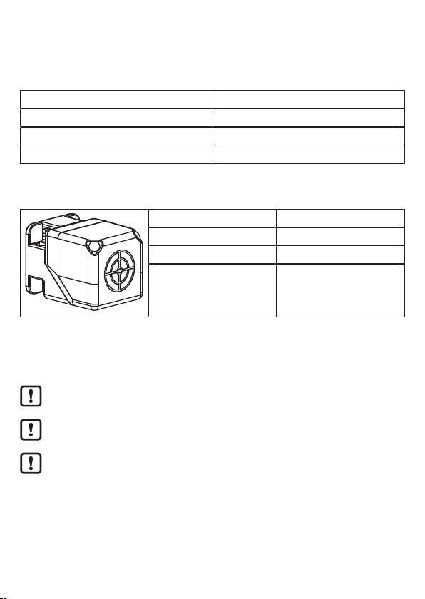
5.3 Device overview....................................................................................... 7
6 Installation....................................................................................................... 7
6.1 Notes on the unit installation.................................................................... 7
6.2 Avoiding interference ............................................................................... 7
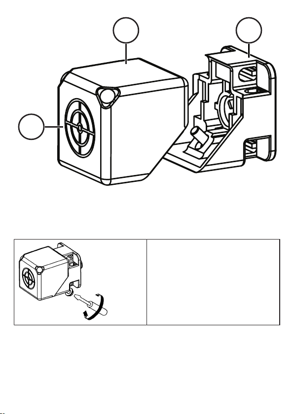
6.3 Mechanical design ................................................................................... 8
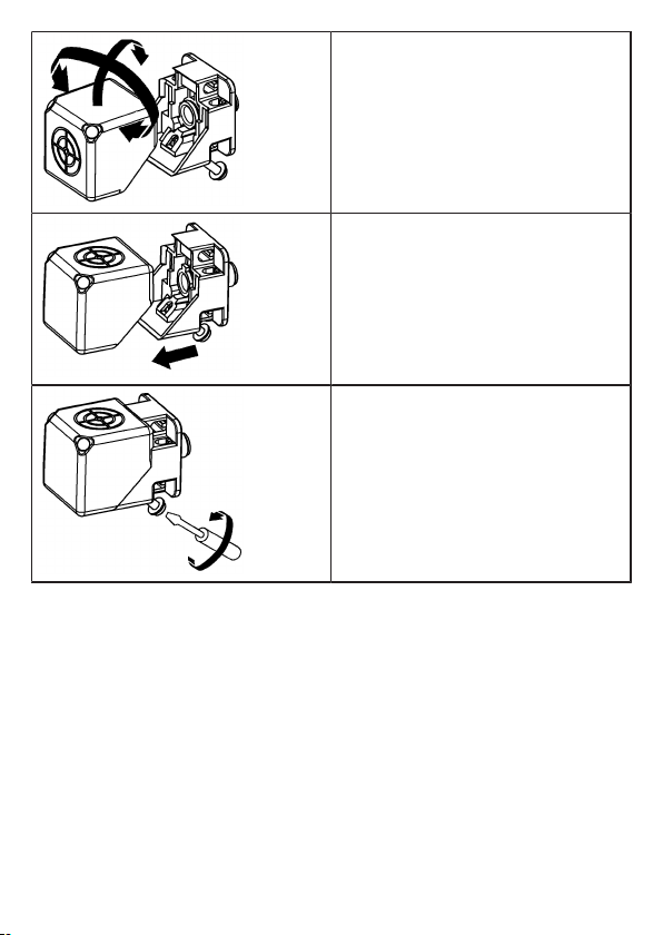
6.4 Alignment of the sensing face.................................................................. 9
6.5 Install device ............................................................................................ 10
6.6 Mounting distances.................................................................................. 12
6.7 Positioning of the ID tag........................................................................... 12
7 Electrical connection....................................................................................... 13
7.1 Wiring....................................................................................................... 13
8 Operating and display elements ..................................................................... 14
9 Operation ........................................................................................................ 15
9.1 CANopen interface .................................................................................. 15
9.1.1 CANopen functions ........................................................................... 15
9.1.2 Change the Node ID and bit rate ...................................................... 16
9.1.3 Set-up ............................................................................................... 17
9.1.4 Use of 32 bit data types .................................................................... 18
9.1.5 Communication types of the process data object (PDO) .................. 18
9.1.6 Object directory (OD) ........................................................................ 19
9.1.7 Error messages................................................................................. 33

3
9.1.8 Monitoring activity via Heartbeat....................................................... 36
9.1.9 Change objects ................................................................................. 37
9.1.10 Process data objects......................................................................... 37
9.1.11 Device status .................................................................................... 39
9.1.12 Deactivate antenna ........................................................................... 42
9.1.13 Select the ID tag type........................................................................ 43
9.1.14 Read information of an ID tag ........................................................... 44
9.1.15 RSSI value ........................................................................................ 44
9.1.16 ID tag detection filter ......................................................................... 44
9.2 Data transfer with an ID tag ..................................................................... 47
9.2.1 Read UID of the ID tag...................................................................... 47
9.2.2 Read data from the ID tag via PDO transfer ..................................... 47
9.2.2.1 Example 1................................................................................. 48
9.2.2.2 Example 2................................................................................. 48
9.2.3 Write data to the ID tag via PDO transfer ......................................... 49
9.2.3.1 Example 1................................................................................. 50
9.2.3.2 Example 2................................................................................. 51
9.2.4 Error handling for PDO transfer ........................................................ 52
9.2.5 Read data from the ID tag via SDO transfer ..................................... 52
9.2.5.1 Example.................................................................................... 53
9.2.6 Write data to the ID tag via SDO transfer ......................................... 53
9.2.6.1 Example.................................................................................... 53
9.2.7 Lock data range on the ID tag via SDO transfer ............................... 54
9.2.7.1 Example.................................................................................... 54
9.2.8 Error codes during SDO transfer ...................................................... 55
9.3 EDS file.................................................................................................... 57
10 Maintenance, repair and disposal................................................................... 58
11 Approvals/standards ....................................................................................... 58
Glossary.......................................................................................................... 59

4
1 Preliminary note
You will find instructions, technical data, approvals and further information using
the QR code on the unit / packaging or at www.ifm.com.
1.1 Symbols used
Requirement
Instructions
Reaction, result
[...] Designation of keys, buttons or indications
Cross-reference
Important note
Non-compliance may result in malfunction or interference.
Information
Supplementary note
1.2 Warnings used
ATTENTION
Warning of damage to property
1.3 Legal and copyright information
© All rights reserved by ifm electronic gmbh. No part of these instructions may be
reproduced and used without the consent of ifm electronic gmbh.
All product names, pictures, companies or other brands used on our pages are the
property of the respective rights owners.
2 Safety instructions [Übersetzung ist nicht mehr
aktuell]
General
•
The unit described is a subcomponent for integration into a system.
–
The system architect is responsible for the safety of the system.

5
–
The system architect undertakes to perform a risk assessment and to create
documentation in accordance with legal and normative requirements to be
provided to the operator and user of the system. This documentation must
contain all necessary information and safety instructions for the operator,
the user and, if applicable, for any service personnel authorised by the
architect of the system.
•
Read this document before setting up the product and keep it during the entire
service life.
•
The product must be suitable for the corresponding applications and
environmental conditions without any restrictions.
•
Only use the product for its intended purpose (Ò Intended use).
•
If the operating instructions or the technical data are not adhered to, personal
injury and/or damage to property may occur.
•
The manufacturer assumes no liability or warranty for any consequences
caused by tampering with the product or incorrect use by the operator.
•
Installation, electrical connection, set-up, operation and maintenance of the
product must be carried out by qualified personnel authorised by the machine
operator.
•
Protect units and cables against damage.
Radio equipment
In general, radio equipment must not be used in the vicinity of petrol stations, fuel
depots, chemical plants or blasting operations.
uDo not transport and store any flammable gases, liquids or explosive
substances near the unit.
Interference of electronic and medical devices
Operation can affect the function of electronic devices that are not correctly
shielded.
uDisconnect the device in the vicinity of medical equipment.
uContact the manufacturer of the corresponding device in case of any
interference.

6
3 Intended use
The read/write head reads and writes ID tags without contact.
The data is made available as process data via the CAN-bus interface.
4 Items supplied
•
Read/write head
The device is supplied without installation and connection accessories.
Available accessories: www.ifm.com.
The optimum function is not ensured when using components from other
manufacturers.
5 Function
5.1 ID tags
The ID tags are passively operated without a battery. The energy required for
operation is provided by the read/write head.
The energy is provided via an inductive coupling. The integrated antenna coil in
the read/write head generates a magnetic field which partly penetrates the
antenna coil of the ID tag. A voltage is generated by induction that supplies the
data carrier with energy.
The device supports ID tags according to ISO 15693.
5.2 CANopen technology
The CANopen communication profile is based on the CAN Application Layer
(CAL) specification of the CiA organisation. CANopen is considered as a robust
fieldbus with highly flexible configuration options. It is used in many different
applications which are based on different application profiles. CANopen comprises
a concept to configure and communicate real-time data using synchronous and
asynchronous messages. Four message types (objects) are distinguished.
1. Administration messages (layer management, network management and
identifier distribution)
2. Service Data Objects (SDO)
3. Process Data Objects (PDO)
4. Predefined Objects (emergency)

7
For further information please refer to the CiA-CAN specification (CiA 301 -
CANopen).
References
http://www.can-cia.org
CAN Application Layer, DS 201 …207 CiA
LSS profile DS305 CiA
CAN-based communication profile DS 301 CiA
CAN specification version 2.0 A Robert Bosch GmbH
5.3 Device overview
DTC510
Article number: DTC510
Function: Read/write head
Type designation: DTCHF MCRWCOUS03
Type: Rectangular
6 Installation
6.1 Notes on the unit installation [Übersetzung ist nicht mehr
aktuell]
When mounting several RFID units adhere to the minimum distances
between the systems.
Flush mounting of a read/write head in metal reduces the read/write
distance.
Device performance can be affected if positioned in the immediate vicinity
of powerful HF emission sources such as welding transformers or
converters.
6.2 Avoiding interference [Übersetzung ist nicht mehr
aktuell]
The device generates a modulated electrical field with a frequency of 13.56 MHz.

8
Avoid interference with data communication:
uDo not operate any devices in the vicinity that use the same frequency band.
wSuch devices are for example frequency converters and switched-mode power
supplies.
If there are other devices in the same frequency band in the vicinity:
uThe mounting distances between the devices should be as large as possible.
uUse the devices in alternating operation.
uSwitch the HF field of the device on/off.
6.3 Mechanical design
On delivery the sensing face is facing the front.
Fig.1: Factory setting

9
3
2
11
Fig.2: Antenna head separated from the fixing element
1 Sensing face 2 Adjustable antenna head
3 Fixing element
6.4 Alignment of the sensing face
uLoosen the screw.

10
uRemove the antenna head from the
fixing element and turn it.
uAttach the fixing element to the antenna
head.
uTighten the screw.
6.5 Install device
uFix the device with 2 M5 screws and nuts.

11
Fig.3: Non-flush mounting
Fig.4: Flush mounting

12
6.6 Mounting distances
Operating mode Distance side (A) Distance front (B)
For reading and writing ≥ 300 mm ≥ 250 mm
6.7 Positioning of the ID tag
For installation in or on metal use the ID tags provided for this purpose.
uAlign the ID tag on the central axis of the antenna of the device.
wThe distance “D” is indicated in the data sheet.
wAll indications apply to static read/write operations.

13
D
Fig.5: Position the ID tag
7 Electrical connection
The device must be connected by a qualified electrician.
Device of protection class III (PC III).
The electrical supply must only be made via PELV/SELV circuits.
uDisconnect power before connecting the device.
7.1 Wiring
uConnect the device to the CAN bus using the M12 connector.
wVoltage is supplied via the CAN bus.
Pin assignment Wiring
M12 connector, A-coded, 5 poles
4
2 1
3
5
1: Shield
2: U+
3: GND
4: CAN high
5: CAN low
The CAN bus connection is almost trouble-free if the following points are
considered:
uUse cables approved for CAN bus.
uTerminate the cables with 120 Ω terminating resistors.
Information on available sockets see: www.ifm.com.

14
8 Operating and display elements
1 2
Fig.6: Display elements
1 LED green: Operating voltage
LED red: Error
2 LED yellow: ID tag
LED State Description
green on Operating status Preopera-
tional
flashes (2.5 Hz) Operating status Operation-
al
flashes alternately with red
LED (2.5 Hz)
Configuration error
flashes alternately with red
LED (0.8 Hz)
Error in the CAN bus
off Operating voltage missing
yellow on ID tag detected
flashes irregularly Hardware error of the device

15
LED State Description
yellow off
•
No ID tag in the field
•
Faulty ID tag in the field
•
Invalid ID tag in the field
red on CAN bus deactivated
flashes alternately with
green LED (2.5 Hz)
Configuration error
flashes alternately with
green LED (0.8 Hz)
Error in the CAN bus
flashes irregularly LSS service activated
9 Operation
9.1 CANopen interface
The read/write head has a standardised CANopen interface according to CiA
DS-301. All measured values and parameters can be accessed via the object
directory (OD). The individual configuration can be saved in the internal
permanent memory.
The device is delivered with node ID 32 and a bit rate of 125 Kbits/s.
uOnly use cables approved for CANopen.
uTerminate the cables using terminating resistors (120 Ω).
wThe ifm cable EVC492 contains integrated terminating resistors.
9.1.1 CANopen functions
The following CANopen functions are available:
•
64 transmit and receive process data objects (TPDO1.. 64, RPDO1.. 64) in two
possible operating modes:
–
individual check via remote transmission request telegram (RTR)
–
event-controlled transmission
•
Error messages via emergency object (EMCY) with support of the:
–
general error register
–
manufacturer-specific status register
–
error list

16
•
Heartbeat monitoring mechanism
•
Status and error indication via LED
•
In addition to the CiA DS-301 functionality there are more manufacturer and
profile-specific characteristics:
–
setting of the Node ID and the bit rate via object directory entry (SDO)
–
configuration and reading/writing of operational data via service data objects
(SDO)
•
Support of the layer settings service (LSS)
•
Support of synchronous process data transmission (SYNC)
9.1.2 Change the Node ID and bit rate
The device supports several options how to change the Node ID and the bit rate.
The device is delivered with the Node ID 32 and a bit rate of 125 Kbits/s.
Each Node ID must only be assigned once in the CANopen network. If a
Node ID is assigned several times, malfunction in the CANopen network
will result.
Change the Node ID and bit rate in the object directory
The Node ID is entered in the object directory in the objects 0x20F0 and 0x20F1.
If the two values are identical, the setting is stored and is active after a software
reset of the device. Values between 1 and 127 may be used as Node ID.
The bit rate is entered in the objects 0x20F2 and 0x20F3. If the two values are
identical, the setting is stored and is active after a software reset of the device.
The following values may be used as bit rate:
Value Bit rate
0 1000 kBits/s
1 800 kBits/s
2 500 kBits/s
3 250 kBits/s
4 125 kBits/s
5 100 kBits/s
6 50 kBits/s

17
Value Bit rate
7 20 kBits/s
If a master is used in the CANopen network for central storage of
parameters, the changed values for Node ID (0x20F0 and 0x20F1) and bit
rate (0x20F2 and 0x20F3) must be additionally entered in the master.
Otherwise the values will be reset during each start of the CANopen
network.
Change the Node ID and bit rate via LSS
Using the layer setting service (LSS) an LSS master can change the Node ID and
bit rate of the device (LSS slave) via the CAN bus. The LSS master sets all LSS
slaves to a configuration mode. Each LSS slave can be unambiguously identified
via the device data (vendor ID, product code, revision number and serial number).
To change the bit rate the LSS master transfers the new bit rate in the
configuration mode with the service "Configure timing bit". The LSS slave replies
to the LSS master if the new bit rate is supported. Then the LSS master transmits
the time "Switch delay" via the service "Activate bit timing" after which the new bit
rate should be activated. After activation the LSS master switches the LSS slave
again to the operating mode.
To change the Node ID the LSS master transfers the new Node ID in the
configuration mode. The LSS slave replies to the master if the new Node ID is
valid. After changing the Node ID the LSS master switches the LSS slave again to
the operating mode.
The new bit rate and Node ID become active after a software reset of the LSS
slave.
9.1.3 Set-up
The CANopen standard CiA301 defines three possible operating states:
Pre-operational
In the pre-operational state no PDO messages (process data) can be transmitted.
The pre-operational state is used to set the sensor parameters or as standby
mode.
During booting in the pre-operational mode, the device reports the bootUP
message "0x700+Node ID" to the CAN bus.

18
Operational
In the operational state all communication services are carried out. The
operational state is used to exchange the process data while in operation.
Stopped
In the stopped state only NMT messages (network management) are possible.
This allows almost complete separation of redundant or faulty sensors from the
bus.
The master or network manager can request the sensor via NMT messages to
change the state accordingly.
9.1.4 Use of 32 bit data types
CANopen defines data types with a maximum size of 64 bits (8 bytes). By means
of the data type, the user data of ID tags is transmitted efficiently via the CANopen
interface. The data type is also used for the default setting of the device and the
EDS file.
However, some controllers can only process data types with a maximum width of
32 bits (4 bytes). In order to support all types of controllers, the device offers
alternative data objects whose data types are restricted to max. 32 bits. These
data objects are marked by the addition “32 bits” in these instructions. Additionally,
an EDS file is supplied for use of the data types that is read by the controller
software.
By default, the device uses 64-bit data types (e.g. for the preconfigured PDOs).
The setting must be adapted to the use of 32-bit data types. The setting can be
changed via the controller software, by reading the corresponding EDS file.
9.1.5 Communication types of the process data object (PDO)
The TPDO can be checked at any time by transmitting a remote transmission
request telegram (RTR). Otherwise the TPDOs are sent automatically as soon as
their value changes (event-driven).
As an option, the CANOpen service “SYNC” can be used (see CiA 301, 7.2.5
Synchronization object (SYNC)). For the synchronised transmission CANopen
provides the SYNC object at which the TPDOs are transmitted after every "nth"
reception of a SYNC telegram.

19
A total of 64 TPDOs and 64 RPDOs is available; on delivery only the first 4 of
each are active. If the configuration of the CANopen network allows it, the
remaining process data objects can also be activated.
In the standard settings, the process data is assigned to the linear address range
of the ID tag. The TPDO1 maps e.g. the first 8 bytes of the user data memory of
the ID tag.
Reading of the memory and transmission of the data via TPDO is effected
automatically as soon as a new ID tag is detected.
Writing of the data to the ID tag is effected in the same way by writing access to
the respective RPDO.
Data transfer per process data object is only possible in the "Operational"
operating status.
The preset TPDOs and RPDOs are allocated 64-bit data objects. For use
of 32-bit controllers, the settings of the PDOs must be adapted.
9.1.6 Object directory (OD)
CANopen communication (CiA 301)
Index
Subindex
Name
(object)
Type
Access
Default
value
PDO
mapping
capability
Save
object
value
0x1000 0x00 Device type u32 ro 0x00000
000
- -
0x1001 0x00 Error register u8 ro 0x00 - -
0x1003 0x01
0x02
Pre-defined error field u32 ro 0x00000
000
- -
0x1005 0x00 COB-ID SYNC u32 rw 0x00000
000
- yes
0x1008 0x00 Manufacturer device
name
vST
R
ro Article
no. of
the de-
vice
- -

20
Index
Subindex
Name
(object)
Type
Access
Default
value
PDO
mapping
capability
Save
object
value
0x1009 0x00 Manufacturer hard-
ware version
vST
R
ro Current
hard-
ware
version
- -
0x100A 0x00 Manufacturer software
version
vST
R
ro Current
software
version
- -
0x1010 0x01 Save parameters
(Save device parame-
ters in non-volatile
memory)
u32 rw 0x00000
000
- -
0x1011 0x01 Load default commu-
nication parameters
u32 rw 0x00000
000
- -
0x1014 0x00 COB-ID EMCY
(COB-ID emergency
message)
u32 rw Node ID
+ 0x80
- -
0x1015 0x00 Inhibit time EMCY
(Inhibit time between
EMCY messages)
u16 rw 0x0000 - yes
0x1017 0x00 Producer Heartbeat
time
(Time difference be-
tween sent heartbeats
in ms)
u16 rw 0x0000 - yes
0x1018 0x01 Vendor ID u32 ro 0x00696
66D
- -
0x02 Product code u32 ro Product
code of
the de-
vice ver-
sion
- -
Other manuals for DTC510
2
Table of contents
Other IFM RFID System manuals
Popular RFID System manuals by other brands

Emka Electronics
Emka Electronics Swing Handles Series quick start guide

Unitech
Unitech HT730 UHF quick start guide

Feig Electronic
Feig Electronic ID ISC.ANT.U500/270 installation manual

GCS
GCS ProxiPen Hardware and software installation guide

Wenglor
Wenglor R18A001 operating instructions

Sanela
Sanela SLZA 38 Instructions for use