26
!
Only trained and authorised experts must install the device and make the electrical connection under full
observance of these installation instructions.
2.1 Equipment layout
A- O
1 Temperature selector with LCD 18 Flow sensor
2 Device cap 19 Temperature selector plug “set T”
3 Lower section, back panel 20 Type plate
4 DHW compression fitting 21 Mounting bracket
5 Cold water compression fitting 22 Stud for mounting bracket
6 Top, back panel 23
Cable grommet (power cable from above/below)
7 Electronics 24 Twin nipple (cold water with shut off valve)
8 Coding card for output selection for
the DDLE LCD 18/21/24 25 Flat packing
9 LED diagnostic “traffic light” for operating
and fault indications 26 Screws/rawl plugs for fixing the back panel in
case of water connection on finished walls
10 Plug-in position from the temperature
selector cable 27 Flow limiter, only for theDDLE LCD 18/21/24
(secured to the cold water pipe)
11 Safety pressure limiter (AP 3) with reset
button 28 Installation and operating instructions
12 Mains terminal 29 Installation template
13 Knock-out for power connection from above 30 Sieve
14 Fixing toggle 31 Flow limiter
15 Outlet sensor 32 Profile washer
16 High limit safety cut-out (STB) with reset
button 33 Support panel
17 Heating system
2.2 Brief description
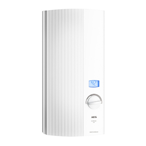
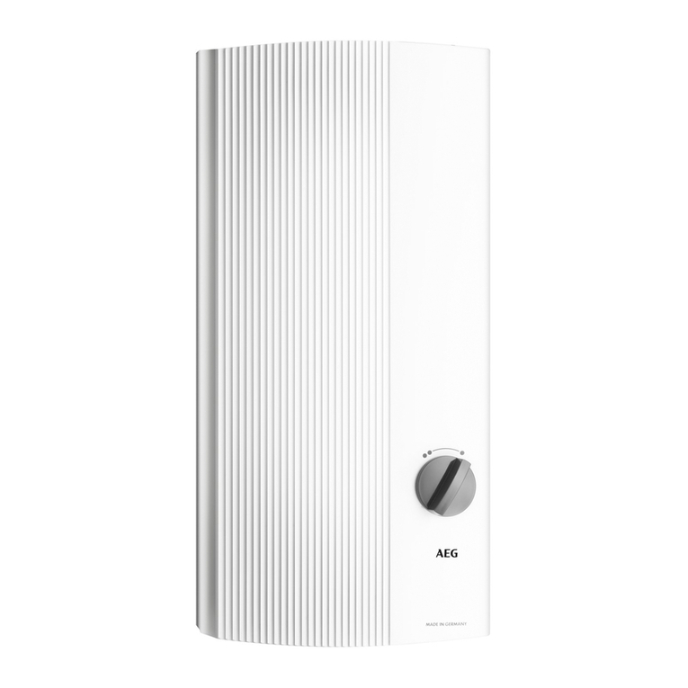
This electronically regulated instantaneous water heater is a pressure device for the heating of cold water to
DIN 1988 / EN 806 that can supply one or several draw-off points.
The bare wire heating system is suitable for hard and soft water areas (for application range, see
"5.2 Application areas").
2.3 Important information
s !IRINTHECOLDWATERSUPPLYCANDESTROYTHEBAREWIREHEATINGSYSTEMINSIDETHEEQUIPMENTORCANTRIP
THESAFETYSYSTEM)FTHEWATERSUPPLYTOTHEINSTANTANEOUSWATERHEATERHASBEENINTERRUPTEDEG
BECAUSEOFARISKOFFROSTORWORKONTHEWATERSYSTEMTAKETHEFOLLOWINGMEASURESPRIORTOTAKINGTHE
EQUIPMENTBACKINTOUSE
2EMOVEFUSESORTRIPTHEAPPROPRIATE-#"S
/PENANDCLOSEATAPDOWNSTREAMOFTHEEQUIPMENTSEVERALTIMESUNTILALLAIRHASBEENVENTED
FROMTHECOLDWATERSUPPLYLINEUPSTREAMANDTHEEQUIPMENT
2EPLACETHEFUSESORRESETTHERELEVANT-#"S
4HEINSTANTANEOUSWATERHEATERISEQUIPPEDWITHANAIRDETECTORWHICHTOTHEGREATESTEXTENT
PREVENTSDAMAGETOTHEHEATINGSYSTEM
)FDURINGOPERATIONAIRISDRAWNINTOTHEINSTANTANEOUSWATERHEATERTHEEQUIPMENTSHUTSDOWN
THEHEATINGLOADFORONEMINUTETHEREBYPROTECTINGTHEEQUIPMENT
s 4APS
n
$IRECTDRAWOFFTAPFORINSTANTANEOUSWATERHEATER!$%O7$MONOLEVERMIXERWITHCHANGEOVER
BATHHANDSHOWERPARTNO
4HEINSTALLATIONMAYBECARRIEDOUTUSINGCOMMERCIALLYAVAILABLEPRESSURETESTEDTAPS
&ORTHERMOSTATICPRESSURETESTEDVALVESSEEINFORMATION2ECOMMENDEDADJUSTMENT
s !LWAYSCAREFULLYOBSERVEALLINFORMATIONINTHESEOPERATINGANDINSTALLATIONINSTRUCTIONS
4HESECONTAINIMPORTANTINFORMATIONREGARDINGSAFETYOPERATIONINSTALLATIONANDMAINTENANCEOFTHIS
EQUIPMENT
2.4 Instructions and regulations
s 4HEINSTALLATIONWATERANDELECTRICALWORKANDCOMMISSIONINGASWELLASTHEMAINTENANCEOFTHIS
equipment, must only be carried out by a qualified contractor in accordance with these instructions.
s 0ERFECTFUNCTIONANDSAFEOPERATIONCANONLYBEASSUREDWHENUSINGORIGINALACCESSORIESANDSPAREPARTS
intended for this equipment.
s /BSERVEALLLOCALLYAPPLICABLEINSTRUCTIONSANDREGULATIONSREGARDINGWATERANDELECTRICALCONNECTIONSSUCH
For contractors
2. Installation instructions

