Aegis Secure R51 Manual

Admin Guide
Aegis Secure R51 - Enhanced ReTransmission Device

CONTENTS
Contents
1. Change Record.......................................................................................................................................................................... 2
2. Description of the Aegis Secure R51 project...................................................................................................................... 3
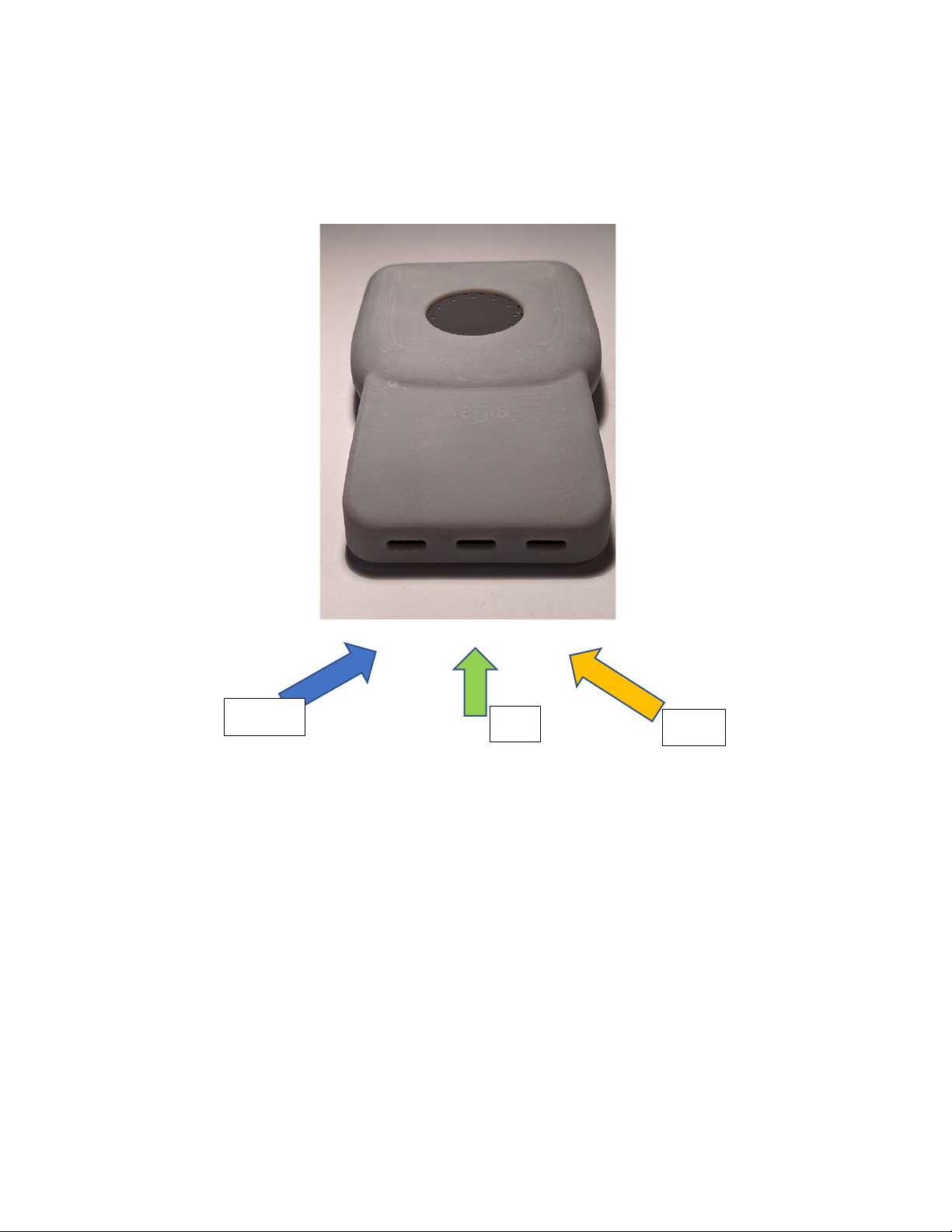
3. Connecting the R51 ERD......................................................................................................................................................... 4
3.1. Step 1: Connecting an EUD..................................................................................................................................................... 4
3.2. Step 2: Connecting the Power for EUD and ERD................................................................................................................ 5
3.3. Step 3: Connecting to the Admin port (only to change networks).................................................................................. 5
4. Using the device........................................................................................................................................................................ 6
4.1. Power on the device................................................................................................................................................................. 6
4.2. Step 1: The start-up timeline...................................................................................................................................................7
4.3. Step 2: Device Setup using the Administration Portal.......................................................................................................7
4.3.1. Logging in................................................................................................................................................................................... 8
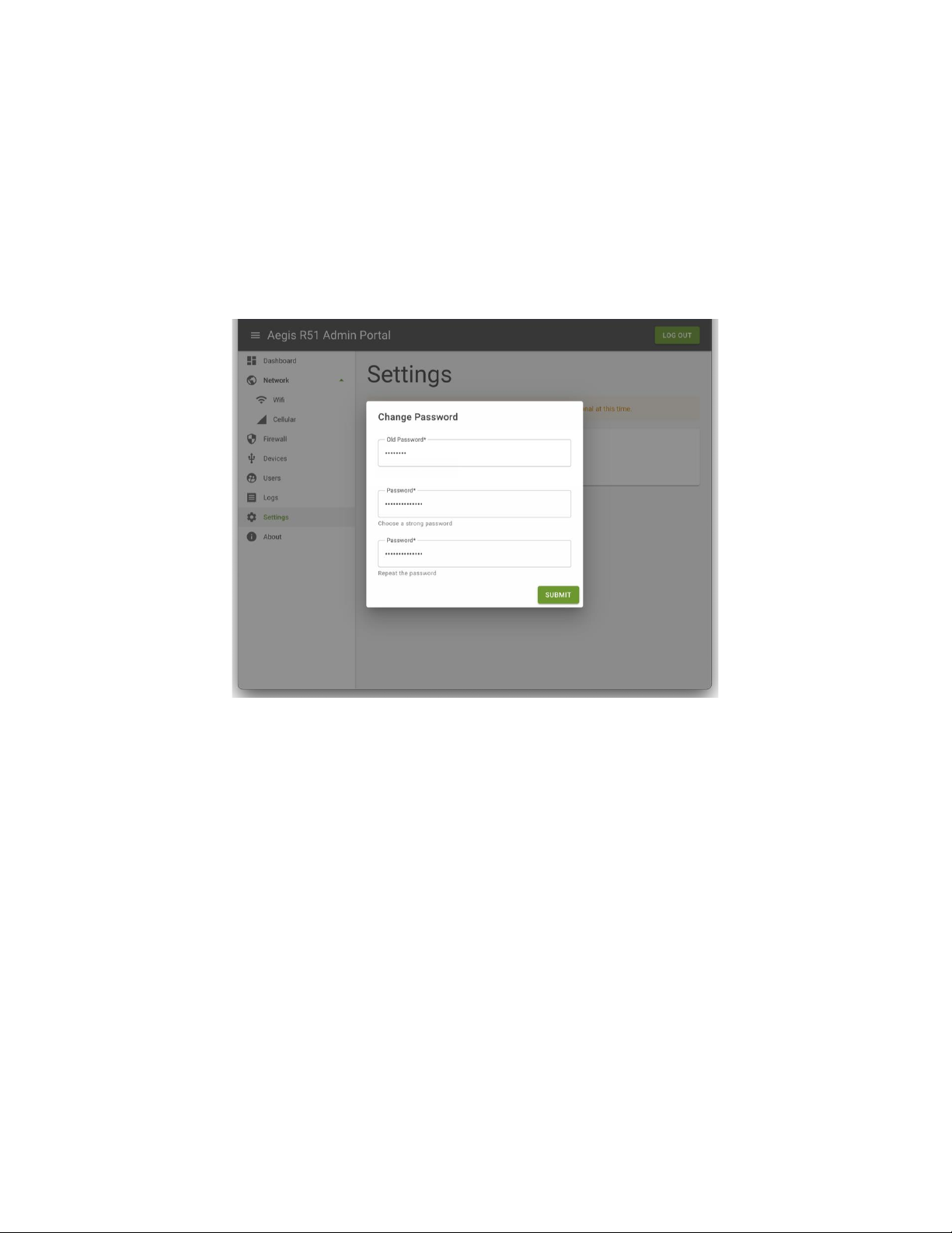
4.3.2. Changing User password ........................................................................................................................................................ 8
4.3.3. Connecting to Wi-Fi (User or Admin roles) .......................................................................................................................10
4.3.4. Activating eSIM (User or Admin roles)............................................................................................................................... 10
4.3.5. Adding, Modifying, or Deleting User Accounts (Admin only)......................................................................................... 12
4.3.6. Modifying Account locking setting...................................................................................................................................... 13
4.3.7. Firewall Tab (Admin role only) ............................................................................................................................................. 13
4.3.8. View Logs (Admin role only)................................................................................................................................................. 14
5. Status Lights.............................................................................................................................................................................17
6. Reporting Issues..................................................................................................................................................................... 18
7. Expected Super User ADB Output (NOTE: only in prototype release).......................................................................... 19
Overview
Welcome to the future of Ultra Secure Mobility with the prototype of our Aegis
Secure R51 device.
This is the administrator guide for the Aegis Secure R51 –Prototype edition,
Release 3. It explains how to connect the device, how to use the device including
configure the device using the Administration Portal and provides information
about status lights.
NOTE: bold NOTE sections indicate known gaps with this release of the ERD
software.

Figure 1: View of ERD case USB ports............................................................................................................................................................. 4
Figure 2: Rear of Case showing magnet.......................................................................................................................................................... 5
Figure 3 Buttons................................................................................................................................................................................................... 6
Figure 4: Admin Portal Dashboard.................................................................................................................................................................... 8
Figure 5: Settings tab.......................................................................................................................................................................................... 8
Figure 6: Change Password Dialog Box........................................................................................................................................................... 9
Figure 7: Wi-Fi Administration Tab................................................................................................................................................................. 10
Figure 8: Cellular Administration Tab.............................................................................................................................................................11
Figure 9: Users Tab............................................................................................................................................................................................ 12
Figure 10: New User Dialog Box..................................................................................................................................................................... 13
Figure 11: Firewall Configuration.................................................................................................................................................................... 14
Figure 12: List of Logs....................................................................................................................................................................................... 15
Figure 13: Log details........................................................................................................................................................................................ 15
Figure 14: ERD in case showing status lights................................................................................................................................................17
Figure 15: Status Lights flow chart ................................................................................................................................................................ 18
1. Change Record
Date
Author
Version
Changes
Approved by
07-21-2021
Rupert Young
1.0
R51 Admin Guide Prototype Edition,
Release 1
Carl Nerup
08-05-2021
Rupert Young
1.1
R51 Prototype Edition Release 2
Carl Nerup
09-15-2021
Rupert Young
1.2
R51 Prototype Edition Release 3
Carl Nerup

2. Description of the Aegis Secure R51 project
The Aegis Secure R51 is the output of Phase 4 of Cog Systems’ Broadband Isolation project. At the completion
of Phase 4, the device will be made commercially available. This is currently scheduled for mid-September 2021.
The Aegis Secure R51 takes a commercially available Retransmission Device (RD), the RelayGo Relay+, and
converts it into a compliant Enhanced ReTransmission Device (ERD) when used in its case. The case attaches the
ERD to a range of End User Devices (EUDs) with three USB-C ports and an integrated USB Mux to control power,
data flows per requirements. The R51 adds bare metal hypervisor technology to provide driver separation and a
firewall/protocol break.
The ERD enables any EUD (mobile phone, tablet, or computer) to safely connect to any mobile or Wi-Fi network.

3. Connecting the R51 ERD
The R51 is designed to be used when properly seated in its case. The case has three USB ports as shown in the picture
below.
Figure 1: View of ERD case USB ports
The left port is the Charging port. The middle port is the EUD port and is the primary data connectivity port. The right
port is the Administration (Admin) port.
3.1. Step 1: Connecting an EUD
The ERD is designed to support any EUD; however, only Mac (running Linux) and PC laptops, and Samsung S20’s
have been verified as EUDs at this time.
1. With a laptop, any USB cable can be used to connect to the EUD port.
2. NOTE: When using a Samsung S20 (known bug), please use an On the Go (OTG) cable to allow the S20 to act
as a host device for the ERD. In future, the included short USB cable can be used. When using an OTG cable
EUD will not receive power from power port. The
3. For other devices, try a regular USB and then a OTG cable. Please report any device that does not work with
either.
Admin
EUD
Charging

Figure 2: Rear of Case showing magnet
To use the magnet on the back of the case, attach the included strike plate to the back of the EUD.
3.2. Step 2: Connecting the Power for EUD and ERD
1. Plug in a USB charging cable to the Charging port.
2. Both the ERD and the EUD will charge. NOTE: EUD will not charge when using OTG cable (known bug).
3. When connected ERD will draw power from EUD.
4. The case blocks data from flowing to either device through the charging port.
NOTE: The included ERD charger from the RD, may fail to charge the device. Please instead use the charger that
came with the EUD or another smart phone.
3.3. Step 3: Connecting to the Admin port (only to change networks)
1. Any device or USB cable can be used when using the Admin port.
2. Plug in the device to use the Admin port.
3. When connecting a device to the Admin port, the ERD will give that device exclusive data access to the ERD
even if EUD is also connected at that time.
NOTE: In the prototype release, any device connected to either the Admin or EUD port can access the Admin portal.
Magnet

4. Using the device
After connecting the ERD to EUD, Admin, and/or power it is ready to prepare the device for use. This section
assumes EUD and or Admin devices are already connected as necessary.
4.1. Power on the device
Figure 3 Buttons
To use the ERD, complete the following:
1. ERD is charged
2. ERD is powered on and booted (Status button is active). While it should not be necessary to boot/reboot
the device in normal use, to power on or reboot press and hold the +button on the top of the ERD for 5
seconds. It will vibrate on success.
3. Networks have been configured through the Admin portal (Section 4.2)
4. Connect to a EUD or Admin device and wait about one minute for tethering to activate.
The sections 4.1 and 4.2 below describe the full boot process and how to configure the device through the Admin
portal. In section 7, at the end of this document, is a version for super users with access to adb shell (available in
this prototype device but not in the commercial product). Adb shell is available after switching into flashboot
mode. To enter flashboot mode, press and hold +and –buttons without EUD connected.
After configuring the device, network configurations are retained for future use.
NOTE: The round button (assistant button) is not active in this version of software.
round

4.2. Step 1: The start-up timeline
NOTE: The boot process is very slow in this prototype release. The full boot takes about fourteen minutes.
Spinning white LED turns on indicating boot is in process. Look for notification of a new USB device on EUD or
Admin device.
Lights will stop as the firewall and admin portal is loaded. This will take about 10 minutes.
EUD or Admin device recognizes ERD as Qualcomm Android device.
The status button becomes available on the ERD device. See section 5 on lights below for more information on
the ERD device.
EUD or Admin device recognizes new wired connection indicating USB tethering is enabled.
To confirm successful boot, Open web browser and navigate to Admin portal at http://192.168.42.129.
When it connects and the page loads, Admin portal fully loaded and ready.
4.3. Step 2: Device Setup using the Administration Portal
When first used the user (login User, password password) and administrator profiles are defined, and password
protected. Administrator profiles can create multiple admin and user profiles for a single device and change user profile
passwords.
An end user access is limited to access the Dashboard, the Network tab to configure additional Wi-Fi and Cellular
networks, the Settings tab to change their password, and the About tab to find links to documentation. NOTE:
Documentation links are not currently active.

Figure 4: Admin Portal Dashboard
4.3.1. Logging in
The Dashboard tab is available without logging in. Other tabs require login to a user or admin profile. Once logged
in access to other tabs is based on the profile type. Directions below assume the user is logged in. Once logged in,
status will be stored until web browser is refreshed. Additional user accounts can be added by an admin user.
4.3.2. Changing User password
Figure 5: Settings tab

1. Click on Settings tab
2. Click on Change Password button
3. Type in old password
4. Type in new password (must include a capital letter, a special character, a number, and is 14 characters
long). Will provide error message if it does not match password requirements.
5. Type in new password again to confirm
6. Hit Submit
Figure 6: Change Password Dialog Box

4.3.3. Connecting to Wi-Fi (User or Admin roles)
Figure 7: Wi-Fi Administration Tab
1. Assumes Admin device is plugged-in via USB into the Admin port
2. From the Admin device web browser, navigate to http://192.168.42.129:8081
3. Select Network tab in the side menu
4. Select Network Mode to Wi-Fi (may already be set)
5. Select Wi-Fi subtab in the side menu
6. Make sure Wi-Fi is turned on
7. In the Wireless Connection section choose the right SSID and enter a password. It takes a couple seconds
for the SSID list to load. The SSID can be manually entered by turning the Manual switch on.
8. Click Connect
After the Wi-Fi network is added, various properties will become available for review. The Wi-Fi will remain in the
system after being added and will automatically connect in the future.
4.3.4. Activating eSIM (User or Admin roles)
NOTE: Requires support from carrier. The ERD has been tested only with AT&T. Necessary certifications for
Verizon are in progress.

Figure 8: Cellular Administration Tab
1. User looks up and records the ERD IMEI. It can be viewed from the Network tab in the Admin portal.
Alternatively, the ERD IMEI is etched on the back of the ERD (visible when removed from case).
2. Carrier representative provides the eSIM (likely as a eSIM QR code card.)
3. Carrier representative will connect the eSIM to the ERD IMEI in their systems.
4. Assumes Admin device is plugged-in via usb into the Admin port
5. From the Admin device web browser navigate to http://192.168.42.129:8081
6. Select Network tab in the side menu
7. Set Network Mode to Cellular (if not already set)
8. Select Cellular subtab in the side menu
9. Click the +button in the Profiles section.
10. Enter the Activation Code of the eSIM. If the eSIM has a QR Code use
this site
to extract the activation
code from an image of the QR Code. It should look something like this:
LPA:1$cust-001-v4-prod-atl2.gdsb.net$A4412879E6202C6EA71CC8D79D083D86
11. Confirmation Code is optional and can be left empty.
12. Click Submit
Eventually, the eSIM should appear in the profile list. There will be no indication in real-time.
Multiple eSIM profiles can be kept for use in the device. Disable the active profile before enabling a new profile.
The active profile is marked with a check mark.
If Wi-Fi and LTE are active at the same time, the ERD will default to Wi-Fi.
After LTE is connected, various properties can be view in the Admin Network tab.

4.3.5. Adding, Modifying, or Deleting User Accounts (Admin only)
To review users and admins click on Users Tab. This will present a list of users on the device, whether they are an
admin or regular user profile and allow any profile to be deleted except the current profile being used.
To delete a profile:
1. Click on Trash icon under actions of the user to be deleted
2. A warning box will be presented to confirm deletion of profile
To modify a profile:
1. Convert a profile to Admin or not an admin click on area below Is Admin
2. Confirm change
Figure 9: Users Tab
To add a new user:
1. Click on User Tab on sidebar
2. Click on +button next to users

Figure 10: New User Dialog Box
3. Enter the new username and password. Password must meet strong password requirements (upper case,
number, special character, and 14 characters long). Warning will be provided if not correct.
4. Select Is Admin toggle to control whether profile is a regular user or admin user.
5. Click Submit to save.
4.3.6. Modifying Account locking setting
1. Select Setting Tab on sidebar.
2. Change value for account locking settings.
3. Click Submit to save.
4.3.7. Firewall Tab (Admin role only)
For debugging purposes (NOTE: in commercial release IPsec will be on by default but is not in this build),
1. To turn on/off IPsec requirement for Whitelisting of IP address destinations. NOTE: In this release there
is a known bug. Make sure admin portal IP address (192.168.42.129) is added to whitelist before
enabling on IPsec otherwise will lock future access to admin port.
2. Hit toggle next to rule
3. Click Confirm to close warning dialog box.

Figure 11: Firewall Configuration
To Add a new IP Address Whitelist:
1. Click +button to right of Whitelist. Enter IP address or range of IP addresses using dash
between start and end IP address.
2. Click Submit.
4.3.8. View Logs (Admin role only)
The device captures logs of all admin changes, user logins as well as firewall events.
To see a list of available logs,
1. Click on Logs tab on sidebar.
2. Click on <or >to move through pages of logs

Figure 12: List of Logs
3. Click on name of log to see details.
Figure 13: Log details


5. Status Lights
To the check the status of the ERD, press the button in the middle of the case. It is surrounded by a ring of lights
that changes color to show the status.
Figure 14: ERD in case showing status lights
Figure 15 below shows the status reporting cycle.
1. First press shows Battery power level (Green lights or red lights depending on battery level) NOTE: Red
lights in next release
2. Next press displays Wi-Fi status and strength (Blue lights)
3. Then LTE status and strength (Orange lights)
4. Further presses repeat Cycle. If not pressed for several minutes, status reporting will default back to the
Idle state.
Battery
1. the number of lights indicates the current percentage level from 0 to 100%.
2. If the device is charging the next LED to ‘fill’ in the battery state will blink. NOTE: Coming in next release
3. Red lights indicate low battery. NOTE: Coming in next release
LTE
1. the number of lights is based on coverage bars.
2. A single light indicates it is searching for coverage.
Ring of Lights

Wi-Fi
1. the number of lights indicates the current signal strength percentage level from 0 to 100%.
5. A single light for Wi-Fi indicates it is disabled.
NOTE: Wi-Fi and LTE signal strengths are updated once per minute so it may not sync with the level shown in
the Admin panel. The charging lights may also take up to six seconds to refresh after inserting or removing the
power supply. The reporting cycle is not triggered by major changes in status but that is being explored for the
next release. NOTE: Low battery and fill blinks coming in next release.
Figure 15: Status Lights flow chart
6. Reporting Issues
Please report any issues discovered while using the ERD or this guide to Aegis so it can be corrected in a future release.

7. Expected Super User ADB Output (NOTE: only in prototype release)
To enter flashboot mode, press and hold + and - buttons. This section assumes you have adb installed and have
adb su access to the device. Enter the shell using adb shell and gain root access with the su command.
Boot ADB Output
Verify that the system is running on only 1 cpu by reading the cpuinfo:
msm8909w:/ # cat /proc/cpuinfo
processor : 0
model name : ARMv7 Processor rev 5 (v7l)
BogoMIPS : 38.40
Features : half thumb fastmult vfp edsp neon vfpv3 tls vfpv4 idiva idivt vfpd32 lpae evtstrm
CPU implementer : 0x41
CPU architecture: 7
CPU variant : 0x0
CPU part : 0xc07
CPU revision : 5
processor : 1
model name : ARMv7 Processor rev 0 (v7l)
BogoMIPS : 0.00
Features : half thumb fastmult vfp edsp neon vfpv3 tls vfpv4 idiva idivt vfpd32 lpae evtstrm
CPU implementer : 0x00
CPU architecture: 7
CPU part : 0000000
CPU revision : 0
...
Observe that the value for BogoMIPS, implementer, part, and revision on cpus 1-3 are all 0.
Verify that selinux is in permissive mode:
Table of contents