Stahl 9146 Series User manual

Typ/Type 9146
Frequenzmessumformer
Frequency Transmitter
Betriebsanleitung
Operating Instruction

2
Inhaltsverzeichnis
1Sicherheitshinweise.....................................................................................................................3
2Normenkonformität......................................................................................................................3
3Funktion.......................................................................................................................................4
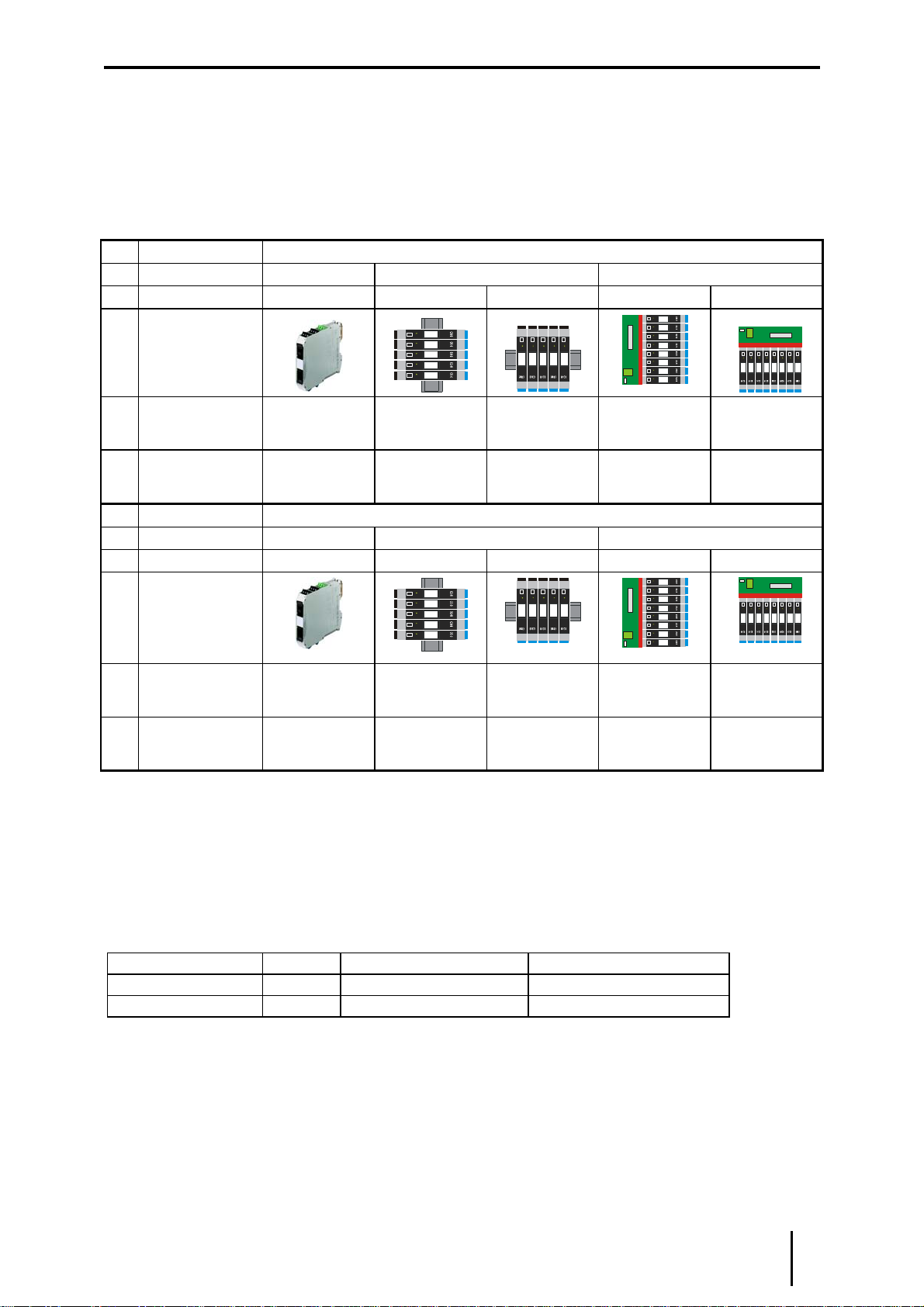
4Kennzeichnung und technische Daten ........................................................................................4
5Projektierung...............................................................................................................................5
5.1 Maximal zulässige Umgebungstemperaturen..........................................................................5
5.2 Verlustleistung.........................................................................................................................5
5.3 Projektierung der Verlustleistung in Schaltschränken..............................................................6
6Anordnung und Montage.............................................................................................................7
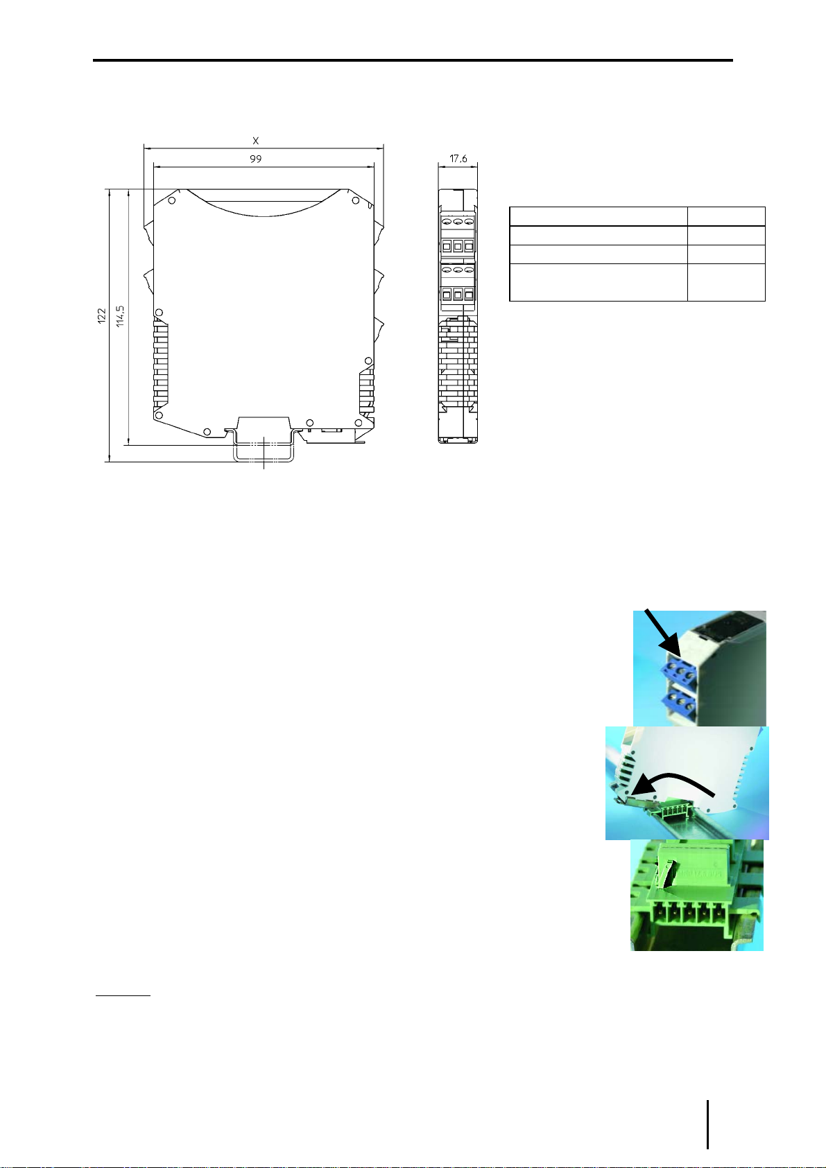
6.1 Maßzeichnung.........................................................................................................................7
6.2 Installation...............................................................................................................................7
6.3 Montage und Demontage........................................................................................................7
7Inbetriebnahme ...........................................................................................................................8
7.1 Anschlüsse..............................................................................................................................8
7.2 Anschluss von Kontakten ........................................................................................................9
7.3 Leitungsfehlererkennung.........................................................................................................9
7.4 Eingang (über Software IS pac Wizard)...................................................................................9
7.5 Signalverarbeitung (über Software IS pac Wizard)................................................................10
7.6 Ausgang (über Software IS pac Wizard)................................................................................10
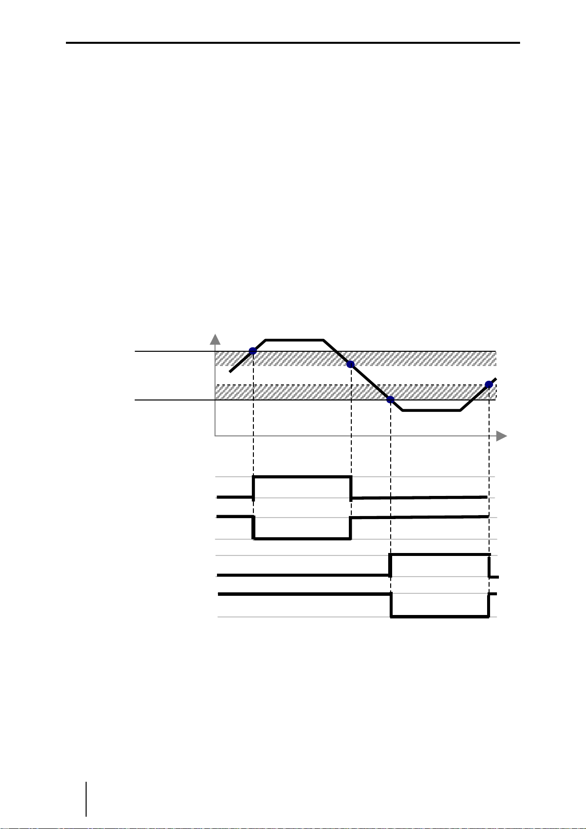
7.7 Grenzwerteinstellung (über Software IS pac Wizard) ............................................................10
7.8 Wiedereinschaltsperre (über Software IS pac Wizard)...........................................................10
7.9 Anlaufüberbrückung ..............................................................................................................11
8Betrieb- und Betriebszustände ..................................................................................................11
9Reparatur und Instandhaltung...................................................................................................11
10 Zubehör und Ersatzteile.............................................................................................................11
Content
1Safety instructions.....................................................................................................................12
2Conformity to standards.............................................................................................................12
3Function.....................................................................................................................................13
4Marking and technical data........................................................................................................13
5Engineering...............................................................................................................................14
5.1 Max. ambient temperatures...................................................................................................14
5.2 Power dissipation ..................................................................................................................14
5.3 Engineering of the power dissipation in cabinets...................................................................15
6Engineering Arrangement and Fitting........................................................................................16
6.1 Dimensions............................................................................................................................16
6.2 Installation.............................................................................................................................16
6.3 Mounting and dismounting.....................................................................................................16
7Commissioning..........................................................................................................................17
7.1 Connections ..........................................................................................................................17
7.2 Connecting contacts..............................................................................................................18
7.3 Line fault detection ................................................................................................................18
7.4 Input (via configuration software IS pac Wizard)....................................................................18
7.5 Signal processing (via configuration software IS pac Wizard)................................................18
7.6 Output (via configuration software IS pac Wizard).................................................................19
7.7 Set-up of the limit value switch (via configuration software IS pac Wizard)............................19
7.8 Re-closing lockout function (via configuration software IS pac Wizard) .................................19
7.9 Start-up delay........................................................................................................................20
8Operation and operational states...............................................................................................20
9Maintenance and repair.............................................................................................................20
10 Accessories and spare parts .....................................................................................................20
EG-Konformitätserklärung / EC-Declaration of Conformity ....................................................................21
EG-Baumusterprüfbescheinigung..........................................................................................................22
EC-Type Examination Certificate...........................................................................................................23

deutsch Betriebsanleitung
Frequenzmessumformer Typ 9146 3
1 Sicherheitshinweise
In diesem Kapitel sind die wichtigsten Sicherheitsmaßnahmen zusammengefasst. Es
ergänzt die entsprechenden Vorschriften, zu deren Studium das verantwortliche Personal
verpflichtet ist.
Bei Arbeiten in explosionsgefährdeten Bereichen hängt die Sicherheit von Personen und
Anlagen von der Einhaltung aller relevanten Sicherheitsvorschriften ab. Das Montage- und
Wartungspersonal trägt deshalb eine besondere Verantwortung. Die Voraussetzung dafür
ist die genaue Kenntnis der geltenden Vorschriften und Bestimmungen.
Bei Errichtung und Betrieb ist Folgendes zu beachten:
• Es gelten die nationalen Montage- und Errichtungsvorschriften (z.B. EN 60079-14)
• Der Frequenzmessumformer ist außerhalb explosionsgefährdeter Bereiche zu
installieren.
• Die Frequenzmessumformer Typen 9146/*0-1*-1* sind auch für den Betrieb in
explosionsgefährdeten Bereichen der Zone 2 und Zone 22 zugelassen.
• Bei Einsatz in Zone 2 sind die Frequenzmessumformer in ein Gehäuse einzubauen,
das den Anforderungen der EN 50 021 genügt.
• Bei Einsatz in Zone 22 sind die Frequenzmessumformer in ein Gehäuse einzubauen,
das den Anforderungen der EN 50 281 genügt.
• Bei Einsatz in Zone 2 und Zone 22 dürfen an die eigensicheren Eingangsstromkreise
auch eigensichere Geräte der Zonen 1, 0, 21 und 20 angeschlossen werden.
• Der Frequenzmessumformer darf nur an Geräte angeschlossen werden, in denen
keine höheren Spannungen als AC 250 V (50 Hz) auftreten können.
• Die sicherheitstechnischen Werte der / des angeschlossenen Feldgeräte/s müssen
mit den Angaben des Datenblattes bzw. der EG-Baumusterprüfbescheinigung
übereinstimmen.
• Bei Zusammenschaltungen mehrerer aktiver Betriebsmittel in einem eigensicheren
Stromkreis können sich andere sicherheitstechnische Werte ergeben. Hierbei kann
die Eigensicherheit gefährdet werden!
• Die nationalen Sicherheits- und Unfallverhütungsvorschriften
• Die allgemein anerkannten Regeln der Technik
• Die Sicherheitshinweise dieser Betriebsanleitung
• Beschädigungen können den Explosionsschutz aufheben.
Verwenden Sie das Gerät bestimmungsgemäß, nur für den zugelassenen Einsatzzweck
(siehe „Funktion“).
Fehlerhafter oder unzulässiger Einsatz sowie das Nichtbeachten der Hinweise dieser
Betriebsanleitung schließen eine Gewährleistung unsererseits aus.
Umbauten und Veränderungen am Gerät, die den Explosionsschutz beeinträchtigen, sind
nicht gestattet. Das Gerät darf nur in unbeschädigtem, trockenem und sauberem Zustand
eingebaut und betrieben werden
2 Normenkonformität
Die Frequenzmessumformer Typen 9146 entsprechen den folgenden Normen bzw. der
folgenden Richtlinie:
• Richtlinie 94/9/EG
• EN 50 014, EN 50 020
• EN 50 021
• EN 50 281

Betriebsanleitung deutsch
4 Frequenzmessumformer Typ 9146
3 Funktion
Die Frequenzmessumformer verarbeitet digitale Frequenzsignale aus dem
explosionsgefährdeten Bereich. Als Signalgebern können Initiatoren nach EN 60 947-5-6
(NAMUR) oder potentialfreien Kontakte / Optokopplerausgänge mit entsprechender
Widerstandsbeschaltung eingesetzt werden. Für unterschiedliche Anforderungen stehen
Ausgangsvarianten mit analogen 0/4...20mA , Grenzwertkontakten oder wahlweise
Impulsausgang zur Verfügung.
4 Kennzeichnung und technische Daten
Hersteller
Typbezeichnung
CE-Kennzeichnung
Ex-Kennzeichnung
Kennzeichnung Explosionsschutz
und
Prüfstelle und Bescheinigungsnummer
Umgebungstemperaturbereich
R. STAHL
9146/*0-1*-1*
c0102
e
II (1) GD [EEx ia] IIC/IIB
II 3 G EEx nAC II T4
BVS 05 ATEX E 171 X
-20 °C … + 70 °C
Sicherheitstechnische Daten
max. Spannung, Uo
max. Strom, Io
max. Leistung, Po
innere Kapazität, Ci/ Induktivität, Li
max. anschließbare Kapazität, CoIIC / IIB
max. anschließbare Induktivität, Lo IIC / IIB
Isolationsspannung Um
10,5 V
23,4 mA
61,4 mW
vernachlässigbar / vernachlässigbar
2,41 µF / 16,8 µF
63 mH / 230 mH
253 V
Weitere Angaben und Wertekombinationen siehe EG-Baumusterprüfbescheinigung
Technische Daten (Auszug aus dem Datenblatt)
Hilfsenergie
Nennspannung UN24 VDC
Nennstrom (bei UNund IAmax) 1 Kanal / 2 Kanäle 55 / 75 mA
Leistungsaufnahme (bei UN) 1 Kanal / 2 Kanäle 1,32 / 1,8 W
Ex i Eingang gem. EN 60 947-5-6
Ausgang
Analogausgang
Bürde
Grenzsignalrelais (nur 9146/10-11-12)
Impulsausgang (nur 9146/10-11-12)
0…20 mA / 4…20 mA
max. 600 Ω
2 Schließer, 30 V / 50 mA
unabhängig einstellbar
1 Schließer, 30 V / 50 mA
Umgebungsbedingungen
Betriebstemperatur -20...+70 °C
Lagertemperatur -40...+80 °C
relative Feuchte (keine Betauung) < 95 %
Weitere technische Daten sind dem aktuellen Datenblatt zu entnehmen.
Bei anderen vom Standard abweichenden Betriebsbedingungen nehmen Sie bitte
Rücksprache mit dem Hersteller.

deutsch Betriebsanleitung
Frequenzmessumformer Typ 9146 5
5 Projektierung
5.1 Maximal zulässige Umgebungstemperaturen
Die Geräte der Reihe IS pac sind über einen weiten Temperaturbereich einsetzbar. Je
nach Geräteausführung und Einbaubedingung ergeben sich unterschiedliche, maximal
zulässige Umgebungstemperaturen.
Belüftung: Ohne Umluft
Installation: Einzelgerät DIN-Schiene pac-Träger
Einbaulage: beliebig vertikal horizontal vertikal horizontal
Kanäle
Typ:
1
9146/10-11-12
70°C 50°C 65°C 40°C 60°C
2
9146/20-11-11
70°C 50°C 65°C 40°C 60°C
Belüftung: Mit Umluft
Installation: Einzelgerät DIN-Schiene pac-Träger
Einbaulage: beliebig vertikal horizontal vertikal horizontal
Kanäle
Typ:
1
9146/10-11-12
70°C 60°C 70°C 50°C 65°C
2
9146/20-11-11
70°C 60°C 70°C 50°C 65°C
5.2 Verlustleistung
In den Datenblättern wird die max. Verlustleistung im Nennbetrieb angegeben. Da in der
Praxis nicht alle Geräte gleichzeitig unter Volllast betrieben werden, erfolgt die
Projektierung üblicherweise mit einer durchschnittlichen Verlustleistung von 70 %. (P70%).
Typ Kanäle max. Verlustleistung 70 % Verlustleistung
9146/10-1*-1* 1 1,1 W 0,77 W
9146/20-1*-1* 2 1,5 W 1,05 W

Betriebsanleitung deutsch
6 Frequenzmessumformer Typ 9146
5.3 Projektierung der Verlustleistung in Schaltschränken
Beim Einbau von Geräten innerhalb von Schaltschränken wird der freie Luftstrom begrenzt
und die Temperatur steigt. Um die Temperaturerhöhung zu minimieren, ist es wichtig, die
Verlustleistung sowie die produzierte Wärme innerhalb des Schrankes zu optimieren.
a) Natürliche Konvektion in geschlossenen Schränken
• Anwendung: bei geringer Verlustleistung und wenn das System in einer staubigen
oder rauen Umgebung installiert ist
• Berechnung der maximal zulässigen Verlustleistung:
Pmax = ∆t * S * K
Pmax [W] max. zulässige Verlustleistung im Schaltschrank
∆t [°C] max. zulässige Temperaturerhöhung
S [m²] freie, wärme-emittierende Oberfläche des Schaltschrankes
K [(W/m²*°C)] thermischer Leitfähigkeitskoeffizient (lackierter Stahl: K = 5,5)
Der errechnete Wert Pmax muss kleiner als die Summe der durchschnittlichen Verlust-
leistungen (70 % der max. Verlustleistung) der eingebauten Geräte sein: Pmax < ∑P70%
b) Natürliche Konvektion in offenen Schränken
• Funktion: die Wärme wird mittels kühler Luftströme zwischen den Geräten verdrängt
• Voraussetzungen:
Luftein und – Auslassöffnungen an den unteren und oberen Enden des Schrankes der
Weg des Luftstroms muss frei von Hindernissen gehalten werden
• Ergebnis: Je nach Ausführung kann die doppelte zulässige Verlustleistung wie unter
a) erreicht werden.
c) Erzwungene Belüftung mit Wärmetauscher in geschlossenen Schränken
• Anwendung: wenn entweder die Umgebung oder die hohe Verlustleistung keine
natürliche Konvektion erlauben
• Funktion: ein Wärmetauscher mit Lüfter saugt Luft in den Schrank und drückt sie in
die Wärmetauscherplatten, die durch einen zweiten Lüfter mit Umgebungsluft gekühlt
werden
• Ergebnis: Je nach Ausführung kann die 5- bis 6-fache zulässige Verlustleistung wie
unter a) erreicht werden.
d) Erzwungene Belüftung in offenen Schränken
• Funktion: Ein oder mehrere Lüfter erzeugen einen Luftstrom von der unteren
Schranköffnung an den Geräten vorbei durch die obere Schranköffnung hinaus.
• Berechnung des notwendigen Luftstroms:
Q = (3,1 * P70%) / ∆t
Q [m³/h] notwendiger Luftstrom
P
70% [W] entstehende Verlustleistung (70 % der max. Verlustleistung)
∆t [°C] zulässige Temperaturerhöhung im Schaltschrank
e) Klimaanlage
• Anwendung: bei heißem Klima – eine Schranktemperatur gleich groß oder geringer
als die Umgebungstemperatur ist erreichbar.
• Funktion: Nutzung eines spezifisches Kältemaschinen-Systems oder des
existierenden Klimasystems für die Schrankkühlung.

deutsch Betriebsanleitung
Frequenzmessumformer Typ 9146 7
6 Anordnung und Montage
6.1 Maßzeichnung
6.2 Installation
Der Frequenzmessumformer ist in der Zone 2, Zone 22 oder außerhalb explosions-
gefährdeter Bereiche zu installieren.
Bei Betrieb in Zone 2 bzw. Zone 22 ist der Temperaturmessumformer in ein Gehäuse
einzubauen, das den Anforderungen der EN 50 021 bzw. EN 50 281 genügt (z.B. in ein
Gehäuse Typ 8146 der Fa. R.STAHL Schaltgeräte GmbH).
6.3 Montage und Demontage
Einbaulage: beliebig
a) Die abziehbaren Klemmen
Alle Geräte sind mit abziehbaren Klemmen versehen. Zum Abziehen die
Klemmen mit z.B. einem Schraubendreher wie im Bild dargestellt
lösen.
b) Montage auf DIN-Schienen nach EN 50 022
Geräte wie im Foto dargestellt ansetzen und auf die DIN-Schiene
aufschwenken. Dabei nicht verkanten. Zur Demontage den Fußriegel
mit einem Schraubendreher etwas herausziehen und das Modul
entnehmen.
c) Montage auf Hutschienen mit installiertem pac-Bus
Geräte wie im Foto oben dargestellt ansetzen und auf die DIN-Schiene mit
dem pac-Bus aufschwenken.
Dabei nicht verkanten.
Hinweis: um eine Verpolung bei der Installation zu Verhindern, sind die pac-Bus-Elemente
mit einer Codierleiste (siehe Foto) und die Module mit dem entsprechendem Codierschlitz
versehen.
Demontage wie unter b) beschrieben.
Maß X
Schraubklemmen 108 mm
Federzugklemmen 128 mm
Schneid-Klemm
Technik 131 mm

Betriebsanleitung deutsch
8 Frequenzmessumformer Typ 9146
c) Montage im pac-Träger
Schwarze und grüne Klemmen entfernen.
Die IS pac Module wie unter a) und b) beschrieben ansetzen und in
den pac-Träger vollständig einschwenken.
Den roten Rasthebel mit leichtem Druck schließen. Der Rasthebel
muss vollständig eingerastet sein.
Zur Demontage den Rastmechanismus mit einem
Schraubendreher wie im Bild dargestellt öffnen. Das Modul wird
aus dem Steckplatz geschoben und kann entnommen werden.
7 Inbetriebnahme
7.1 Anschlüsse
Typ 9146/10-11-12
A, B: Grenzwertrelais A, Grenzwertrelais B Konfiguration Kapitel 7.6
Typ 9146/20-11-11

deutsch Betriebsanleitung
Frequenzmessumformer Typ 9146 9
7.2 Anschluss von Kontakten
Beschaltung bei spannungsfreien Kontakten am Eingang:
Drahtbrucherkennung: 22 kΩparallel
Kurzschlusserkennung: 2,7 kΩin Reihe
Die Beschaltung ist in unmittelbarer Nähe des Kontaktes
vorzunehmen.
7.3 Leitungsfehlererkennung
Auf der Frontseite des Frequenzmessumformers befindet sich ein 4-poliger DIP Schalter.
Leitungsfehlererkennung LF
deaktiviert *) aktiviert
Kanal 1
Kanal 2
*) Standardeinstellung bei Auslieferung
Leitungsfehler und Hilfsenergieausfall werden über LED, Fehlermeldekontakt am Modul
und Sammelfehlermeldung über pac Bus (siehe Kapitel 7.1) signalisiert.
Die Änderung der DIP-Schalter-Einstellungen ist im Betrieb auch in der Zone 2 und bei
angeschlossenen, eigensicheren Eingangssignalen zulässig.
Das Verhalten des Ausgangssignals wird mittels IS pac Wizard Software eingestellt (Siehe
7.6). Hier kann die Leitungsfehler auch komplett deaktiviert werden. (Diese Einstellung
bestimmt das Verhalten des Gerätes, der DIP Schalter ist in diesem Fall wirkungslos.)
7.4 Eingang
(über Software IS pac Wizard)
Der Frequenzmessumformer bietet verschiedene Betriebsarten, die in abhängig von der
Anwendung eingestellt werden. Die Defaulteinstellung ist die Betriebart „Frequenz über
Periodeneinstellung“.
Auswahl Beschreibung
Zähler (0...65535)
Überlauf:
Eingehende Impulse werden gezählt. Das analoge
Ausgangssignal (0/4...20mA) wird linear zum Zählerwert
erhöht. Der maximale Zählerwert kann eingestellt
werden.
Wird der Überlauf aktiviert, dann fängt der Zähler beim
Überschreiten des maximalen Zählerwertes wieder von
neuem an zu zählen und das Ausgangssignal folgt.
(Sägezahn).
Bei ausgeschaltetem Überlauf bleibt der Zähler und das
Analogsignal auf dem maximalen Wert stehen.
Zurücksetzen über den frontseitigen DIP-Schalter ADJ
(OFF-ON-OFF oder ON-OFF-ON)
Frequenz über
Periodenmessung Für Messungen im Bereich 1mHz bis 1kHz
Frequenz über Ereignisse
(50, 200 oder 1000 ms) Für Messungen im Bereich 1kHz bis 20kHz
2,7
k
kΩ
22 k
Ω
LF1
LF2
ON
OFF
1
2
LF1
LF2
ONOFF
1
2

Betriebsanleitung deutsch
10 Frequenzmessumformer Typ 9146
7.5 Signalverarbeitung
(über Software IS pac Wizard)
Die Auswahl erlaubt die Einschränkung des Frequenzbereichs zur weiteren Verarbeitung
im Modul. Der minimale Wert des Analogausgangs entspricht der eingestellten minimalen
Frequenz und in der selben Art und Weise verhält es sich mit den maximalen Werten.
Der Anwender kann damit den für Ihn relevanten Frequenzbereich festlegen und auf den
Bereich des Ausgangssignals (0...20mA oder 4...20mA) beziehen.
7.6 Ausgang
(über Software IS pac Wizard)
Hier können sie das Verhalten des Analog- und Impulsausgangs konfigurieren.
Analogausgang: Neben der Auswahl ob das Analogsignal Werte zwischen 0...20mA oder
4...20mA annehmen soll, können sie das Verhalten des Ausgangs im Fehlerfall definieren.
Sie haben die Auswahl zwischen „Fehlerwert ausgeben“ (frei wählbar), „Letzten Wert
halten“ oder „ Fehlererkennung aus“
Impulsausgang: Der Impulsausgang (Relaisausgang B) kann aktiviert und deaktiviert
werden. Zusätzlich lässt sich ein Teilerverhältnis zwischen 1 und 20.000 eingeben.
7.7 Grenzwerteinstellung
(über Software IS pac Wizard)
Die Grenzwertfunktion wird mit Hilfe der Software IS pac Wizard konfiguriert.
Die folgende Darstellung soll die Einstellmöglichkeiten der Grenzwertkontakte der Relais A
und B zeigen. Es handelt sich hier um ein Beispiel, andere Zuordnungen sind möglich.
Einstellung im IS pac Wizard:
„Ein oberhalb Grenzwert“
„Aus oberhalb Grenzwert“
„Ein unterhalb Grenzwert“
„Aus unterhalb Grenzwert“
Bei detektiertem Leitungsfehler nehmen die Grenzwertrelais die eingestellte Wirkrichtung
ein, d.h. bei „Aus oberhalb Grenzwert“ fallen die Relais ab . Dies ist die empfohlene
Einstellung für sicherheitsgerichtete Schaltungen.
7.8 Wiedereinschaltsperre
(über Software IS pac Wizard)
Die Widereinschaltsperre wird mit Hilfe der Software IS pac Wizard konfiguriert.
Die Wiedereinschaltsperre sorgt dafür, das bei Erreichen eines Grenzwertes der
Grenzwertkontakt in Arbeitsstellung (EIN oder AUS siehe Kapitel 7.6) verbleibt, auch wenn
die Prozessgröße, die zum Ansprechen führte nicht mehr wirksam ist. Die Funktion dient
dazu, dass Grenzwert Über –oder Unterschreitungen vom Personal nicht übersehen
werden.
Grenzwert A
Grenzwert A - Hysterese
Grenzwert B +Hysterese
Grenzwert B
t

deutsch Betriebsanleitung
Frequenzmessumformer Typ 9146 11
Auswahl Beschreibung der Funktion
„Deaktiviert“ Werkseinstellung – Funktion ausgeschaltet
„Aktiviert“
Funktion wie oben beschrieben. Die nach Kapitel 7.6 eingestellte Betriebsart („Ein“ oder „Aus“)
wird beim Eintreten des Ereignisses gehalten. Die Wiedereinschaltsperre wird zurückgesetzt durch
das Betätigen des DIP-Schalters LF1 oder LF2 (OFF-ON-OFF oder ON-OFF-ON) oder
kurzzeitiges Aus- und Einschalten des Gerätes. Bei gleichzeitig auftretenden Fehlerfall nehmen die
Grenzwertrelais den Alarmzustand ein (Bsp.: Ein oberhalb Grenzwert -> im Fehlerfall: EIN)
7.9 Anlaufüberbrückung
Die Anlaufüberbrückung sorgt dafür, das bei den Grenzwerteinstellungen „ein unterhalb
Grenzwert“ oder „aus unterhalb Grenzwert“ der Grenzwertkontakt trotz bestehender
Grenzwertunterschreitung am Eingang nicht aktiviert wird. Diese Funktion erlaubt des
Anlauf einer Maschine oder Anlage ohne entsprechende Alarmmeldung.
Bei aktivierter Anlaufüberbrückung sorgt die erste Flanke am Eingang für den Start der
Funktion. Eine erneute Aktivierung wird durch eine kurzzeitige Unterbrechung der
Stromversorgung ermöglicht.
8 Betrieb- und Betriebszustände
Bevor Sie das Gerät in Betrieb nehmen, stellen Sie sicher, dass
• das Gerät vorschriftsmäßig im korrekten Steckplatz installiert wurde
• das Gerät nicht beschädigt ist
• die Kabel ordnungsgemäß angeschlossen sind
9 Reparatur und Instandhaltung
Es wird empfohlen, Reparaturen an unseren Geräten ausschließlich durch den Hersteller
durchführen zu lassen. In Ausnahmefällen kann die Reparatur auch durch eine andere,
zugelassene Stelle erfolgen. Die Geräte sind wartungsfrei.
Fehlersuchplan:
Fehlererkennung Fehlerursache Fehlerbehebung
LED „PWR“ erloschen - Hilfsenergie ausgefallen
- Gerätesicherung defekt
- Hilfsenergieversorgung verpolt
Hilfsenergieversorgung kontrollieren.
Bei defekter Sicherung das Gerät zur Reparatur geben.
Korrekte Polung herstellen
LED „LF“ Leitungsfehler
leuchtet ständig - Schaltelement nicht korrekt
angeschlossen
- Schaltelement funktioniert nicht
entsprechend NAMUR
Korrekte Verdrahtung des Schaltelementes
sicherstellen.
Spannungsfreie Kontakte entsprechend Punkt 7.2 mit
zusätzlichen Widerständen beschalten.
Keine Änderung des
Schaltzustandes am
Ausgang trotz Aufleuchten
der gelben LED „OUT“
- Vertauschung der abziehbaren
Klemmen Stecken sie die abziehbaren Klemmen an den dafür
vorgesehenen Anschluss im Gerät.
Führen die beschriebenen Vorgehensweisen nicht zum gewünschten Erfolg, wenden Sie
sich bitte an unsere nächste Vertriebsniederlassung. Zur schnellen Bearbeitung benötigt
diese von Ihnen folgende Angaben:
• Typ und Seriennummer,
• Kaufdaten,
• Fehlerbeschreibung,
• Einsatzzweck (insbesondere Eingangs-/Ausgangsbeschaltung)
10 Zubehör und Ersatzteile
Verwenden Sie nur Original-Zubehör sowie Original-Ersatzteile der Fa. R.STAHL
Schaltgeräte GmbH.
IS pac Wizard 9199/20-01 bestehend aus PC-Software für Windows 98, NT, 2000, XP
und Programmierkabel für PC mit RS 232 Schnittstelle
Version: 3.xx oder höher.

Operating Instructions english
12 Frequency Transmitter Type 9146
1 Safety instructions
The most important safety instructions are summarised in this chapter. It is intended to
supplement the relevant regulations which must be studied by the personnel responsible.
When working in hazardous areas, the safety of personnel and plant depends on
complying with all relevant safety regulations. Assembly and maintenance staff working on
installations therefore have a particular responsibility. The precondition for this is an
accurate knowledge of the applicable regulations and provisions.
When installing and operating the device, the following are to be observed:
• The national installation and assembly regulations (e.g. EN 60079-14) apply.
• The frequency transmitter may be installed in Zone 2, Zone 22 or outside of the
hazardous area.
• If installed in Zone 2, the frequency transmitter is to be fitted in an enclosure that which
meets the requirements of EN 50 021.
• If installed in Zone 22, the frequency transmitter is to be fitted in an enclosure that which
meets the requirements of EN 50 281.
• If installed in Zone 2 and Zone 22, devices connected to the intrinsically safe input
circuits of Zones 1, 0, 21 and 20 may be connected.
• The frequency transmitter may only be connected to devices which will not be subjected
to voltages higher than AC 250 V (50 Hz).
• The safe maximum values of the connected field device(s) must correspond to the values
of the data sheet or the EC-type examination certificate.
• Interconnecting several active devices in an intrinsic safety circuit may result in other
safe maximum values. This could endanger the intrinsic safety!
• National safety and accident prevention regulations.
• Generally recognised technical regulations.
• Safety guidelines in these operating instructions.
• Any damage can compromise and even neutralise the explosion protection.
Use the device in accordance with the regulations and for its intended purpose only (see
“Function”).
Incorrect or non-permissible deployment and/or non-compliance with the instructions of this
operating manual shall invalidate any warranty by us.
No changes to the devices or components impairing their explosion protection are
permitted.
Further, the device may only be fitted if it is undamaged, dry and clean.
2 Conformity to standards
The frequency transmitter Type 9146 complies with the following standards and directives:
• Directive 94/9/EC
• EN 50 014, EN 50 020
• EN 50 021
• EN 50 281

english Operating Instructions
Frequency transmitter Type 9146 13
3 Function
The frequency transmitter converts intrinsically safe digital frequency signals of contacts,
proximity switches or optoelectronic couplers into a proportional analogue 0/4…20mA
signal. Additionally it offers two limit value relays which allow to control rotational speed.
As a third function the module offers a pulse output with optional divider.
4 Marking and technical data
Manufacturer
Type designation
CE marking
Ex-marking
Explosion protection marking
and
Testing authority and certificate number
Ambient temperature range
R. STAHL
9146/*0-1*-1*
c0102
e
II (1) GD [EEx ia] IIC/IIB
II 3 G EEx nAC II T4
BVS 05 ATEX E 171 X
-20 °C … + 70 °C
Safety data
Max. voltage Uo
Max. current Io
Max. power Po
Internal capacitance, Ci/ inductance, Li
Max. connectable capacitance, CoIIC / IIB
Max. connectable inductance, LoIIC / IIB
Insulation voltage Um
10,5 V
23,4 mA (linear characteristics)
61,4 mW
negligible
2,41 µF / 16,8 µF
63 mH / 230 mH
253 V
See EC-type examination certificate for further information and value combinations
Technical data (excerpted from the data sheet)
Power supply
Nominal voltage UN24 V DC
Nominal current (at UNand IAmax) 1 / 2 channels 55 / 75 mA
Power consumption (when voltage = UN) 1 / 2 ch 1,32 / 1,8 W
I.S. input Acc. EN 60947-5-6
Output
Analog output
Max. load
Limit value relay (only 9146/10-11-12)
Pulse output (only 9146/10-11-12)
0…20 mA / 4…20 mA
max. 600 Ω
2 NO contacts, 30 V / 50 mA,
independently configurable
1 NO contact, 30 V / 50 mA
Ambient conditions
Operating temperature -20...+70 °C
Storage temperature -40...+80 °C
Relative humidity (no condensation) < 95 %
Additional technical data can be found in the current data sheet. www.ispac.info
Please consult with the manufacturer before operating under conditions which
deviate from the standard operating conditions.

Operating Instructions english
14 Frequency Transmitter Type 9146
5 Engineering
5.1 Max. ambient temperatures
The IS pac isolators can be used over a wide temperature range. Depending on the
isolator version and installation method different maximum ambient temperatures may
result.
Ventilation: without ventilation
Installation: Single unit DIN-rail pac-Carrier
Orientation: any vertical horizontal vertical horizontal
Channels
Type:
1
9146/10-11-12
70°C 50°C 65°C 40°C 60°C
2
9146/20-11-11
70°C 50°C 65°C 40°C 60°C
Ventilation: with ventilation
Installation: Single unit DIN-rail pac-Carrier
Orientation: any vertical horizontal vertical horizontal
Channels
Type:
1
9146/10-11-12
70°C 60°C 70°C 50°C 65°C
2
9146/20-11-11
70°C 60°C 70°C 50°C 65°C
5.2 Power dissipation
Data sheets are describing the maximum power dissipation in standard operation (output
20 mA; power supply 24 V DC; load = 250 Ω). In practice not all isolators are working with
full load. Therefore engineering is done typically with an average power dissipation of 70 %
(P70%).
Type Channels max. power dissipation 70 % power dissipation
9146/10-11-12 1 1,1 W 0,77 W
9146/20-11-11 2 1,5 W 1,05 W

english Operating Instructions
Frequency transmitter Type 9146 15
5.3 Engineering of the power dissipation in cabinets
When electronic devices are integrated in cabinets free air movement is restricted and the
temperature rises. To minimise the temperature rise it is important to optimise the power
dissipation as well as the elimination of the produced heat inside a cabinet.
a) Natural Convection in closed cabinets
• Application: when the dissipated power is moderate and when the system operates in
a dusty or harsh environment
• Calculation of the maximum allowed power dissipation:
Pmax = ∆t * S * K
Pmax [W] max. allowed power dissipation in the cabinet
∆t [°C] max. allowed temperature rise
S [m²] free, heat emitting surface of the cabinet
K [(W/m²*°C)] thermal emitting coefficient (K=5.5 for painted steel sheets)
The calculated value for Pmax has to be smaller than the total average power dissipation
(70 % of max. power dissipation) of the installed isolators: Pmax < ∑P70%
b) Natural convection in open cabinets
• Function: the heat is removed by cool air flowing through the devices
• Requirements:
- inlet and outlet ports in the lower and upper ends of the cabinet
- the air flow path must be kept free from obstacles.
• Result: Depending on the engineering the improvement can reach a two times
higher power dissipation as with a)
c) Forced ventilation with heat exchanger in closed cabinets
• Application: when either the harsh environment or the high dissipated power do not
allow natural convection
• Function: a heat exchanger with a fan pulls the air into the cabinet and pushes it into
the heat exchanger plates that are cooled by the external ambient air moved by a
second fan.
• Result: Depending on the engineering the improvement can reach a 5 or 6 times
higher power dissipation as with a)
d) Forced ventilation in open cabinets
• Function: the filtered air is taken from the bottom cabinet openings by one or more
fans, flows through the devices, and finally exits at the top of the cabinet.
• Calculation of the required air flow:
Q = (3.1 * P70%) / ∆t
Q [m³/h] required air flow
P70% [W] dissipated power (70 % of max. power dissipation)
∆t [°C] allowed temperature rise in the cabinet
e) Air conditioned cabinets
• Application: for hot climates - it is possible to reach a cabinet temperature equal or
even lower than the ambient temperature
• Function: a specific refrigerating system or the existing air conditioning system can be
used for cabinet conditioning

deutsch Betriebsanleitung
Frequenzmessumformer Typ 9146 16
6 Engineering Arrangement and Fitting
6.1 Dimensions
6.2 Installation
The frequency transmitter may be installed in Zone 2, Zone 22 or outside of the hazardous
area.
In the case of operation in Zone 2 or Zone 22, the frequency transmitter must be fitted in an
enclosure which complies with the requirements of EN 50 021 or EN 50 281 (e.g. in an
enclosure type 8146 from the R. STAHL Schaltgeräte GmbH company).
6.3 Mounting and dismounting
Mounting position: as required
a) Detachable terminals
All devices are provided with detachable terminals. A screwdriver is
needed to remove the terminals (as shown in the picture).
b) Mounting on DIN rails in accordance with EN 50 022
Set the device on the DIN rail and tilt/snap onto the rail as depicted.
Do not tilt at an angle to either side when snapping onto the pac-Bus.
To dismount, use a screwdriver to gently pry up the lock on the
mounting foot and then remove the module.
c) Mounting on DIN rails fitted with a pac-Bus
As depicted in the photo, set the device in position on the pac-Bus
(already mounted on the DIN rail) and tilt/snap until it locks in.
Do not tilt at an angle to either side when snapping onto the pac-Bus.
Note: In order to prevent pole reversal during installation, the pac-Bus
elements have been equipped with a keyed connection plug (see photo).
The module is fitted with a matching slot.
Dismount as described below in b).
Dimension X
Screw terminals 108 mm
Spring clamp terminals 128 mm
Insulation cutting
terminals 131 mm

english Operating Instructions
Frequency transmitter Type 9146 17
c) Mounting in the pac-Carrier
Remove the black and green terminals.
Set the IS pac modules in place as described in a) and b) and
completely tilt/snap into the pac-Carrier.
Close the red latching lever using gentle pressure. The latching
lever must engage completely.
To dismount, use a screwdriver to open the latching mechanism as
shown in the picture. The module is nudged out of the slot and can
be removed.
7 Commissioning
7.1 Connections
9146/10-11-12
A, B: Relay A, Relay B configuration see chapter 7.6
9146/20-11-11
Hazardous
area Safe area
Hazardous
area Safe area

Operating Instructions english
18 Frequency Transmitter Type 9146
7.2 Connecting contacts
Mode of connection for line fault identification (potential free contacts at the I.S. input)
Open circuit identification: 22 kΩin parallel
Short circuit identification: 2,7 kΩin series
The loading has to carry out in direct proximity of the contact.
7.3 Line fault detection
On the front side of the frequency transmitter is situated a 4 pole DIP switch.
Line fault detection LF
deactivated *) activated
channel 1
channel 2
*) Default set-up
Line faults and loss of power are indicated by LED on the front side, contact (PIN 9) and
common fault contact via the optional pac-Bus (see chapter 7.1). The behaviour of the
output signal can be set as described in chapter 7.6. The line fault detection can be
switched of via the IS pac Wizard software. In this case the DIP switches are without
function. Changing settings via DIP switches during operation is also permitted in Zone 2
and on circuits carrying intrinsically-safe input signals.
7.4 Input
(via configuration software IS pac Wizard)
The frequency transmitter offers different operating modes, which are selected depending
on the application. The default set-up is the operating mode “Frequency via period”.
Selection Description
Counter (0…65535)
Overflow:
Received input pulses are counted. The analog output
signal (0/4…20mA) is linearly increased. The maximum
counter value can be set-up.
If the overflow is activated, the counter starts again after
passing the max. value and the analog signal follows.
If the overflow is deactivated, the counter and the analog
signal is locked when the max. counter value is reached.
Reset via DIP switch ADJ (OFF-ON-OFF or ON-OFF-ON)
Frequency via period For measurements in the range of 1mHz to 1kHz
Frequency via events
(50, 200 or 1000 ms) For measurements in the range of 1kHz to 20kHz
7.5 Signal processing
(via configuration software IS pac Wizard)
These selection allows to customize the frequency range for the processing in the module.
The minimum value of the analogue output signal corresponds to the selected minimum
frequency. The same applies for the maximum values. The operator can set-up the
frequency range and refer it to the range of the output signal (0…20mA or 4…20mA).
2.7
k
kΩ
22 k
Ω
LF1
LF2
ON
OFF
1
2
LF1
LF2
ONOFF
1
2

english Operating Instructions
Frequency transmitter Type 9146 19
7.6 Output
(via configuration software IS pac Wizard)
The selection allows to define the behaviour of the analogue and pulse output.
Analogue Output: Please select the range of the analogue output signal between 0…20mA
and 4…20mA. Furthermore you may define the behaviour of the output in case of detected
fault: - Output fault value (user definable)
- Holt last value
- Fault detection off
Pulse output: The pulse output can be activated or deactivated (default). The setting
applies to relay B. Additionally the operator can set-up divider ration between 1 and
20.000.
7.7 Set-up of the limit value switch (via configuration software IS pac Wizard)
The limit value switch has to be configured by the software IS pac Wizard. The following
scheme illustrates different ways to set-up the thresholds of the relay contacts A and B.
The scheme is an example, other set-ups are possible:
Set-up in the IS pac Wizard:
„closes if value > limit value“
„opens if value > limit value“
„closes if value < limit value“
„opens if value < limit value“
In case of an detected line fault the limit value switch will turn to the selected alarm state
e.g. for „opens if value > limit value“ the contact will open. This is the recommended set-up
for safety circuits.
7.8 Re-closing lockout function (via configuration software IS pac Wizard)
The re-closing lockout function has to be configured by the software IS pac Wizard. The
relay contact is remaining in the working position (i.e. NO contact remains closed) even if
the process value is returning to value which is below or above the set point. The re-closing
lockout function avoids that the operator miss an detected threshold event.
Limit value A
Limit value A - Hysteresis
Limit value B +Hysteresis
Limit value B
t

Operating Instructions english
20 Frequency Transmitter Type 9146
Selection Description
“deactivate” Default set-up – function disabled
“active”
Function as described above. The selected operating mode (“open” or “closes” see chapter 7.6.) is
kept even if the trigger is not available. The re-closing lockout function is reset by actuating the DIP
switch LF1 or LF2 (ON-OFF-ON or OFF-ON-OFF) or a short disruption of the power supply. In
case of a detected error in parallel the limit value contact turns to the selected alarm state (e.g.
“opens if value > limit value” the contact opens)
7.9 Start-up delay
The start-up delay overrides an alarm, if the setting “closes if value < limit value” or “opens
if value < limit value” is selected. The function allows to start-up machines and engines
without an alarm. Setting range: 0…999sec.
The activated function is triggered by the first slope of the input signal. The start-up delay is
re-activated if the power supply is shortly interrupted.
8 Operation and operational states
Before commissioning the device, please ensure that:
• the device has been installed in the correct slot and in accordance with the standards
• the device is not damaged
• the cables are connected properly
9 Maintenance and repair
It is recommended that all repairs to our devices be carried out by R. STAHL. In
exceptional cases, repair may be performed by approved third-parties.
The devices are maintenance-free.
Troubleshooting chart:
Error detection Malfunction cause(s) Trouble-shooting
“PWR” LED not lit Power supply failure or device
fuse is defective Check power supply.
If device fuse is defective, send device in for repair.
Output signals faulty Sensor is incorrectly connected
Sensor does not work acc. to
NAMUR
Check connections (see 6.1)
Potential free contacts acc. chapter 7.2 need additional
resistors in series and parallel.
If the procedure described above does not obtain the desired result, please contact your
local R.STAHL sales and service representative. In order to quickly process your request,
please provide us with the following information:
• Type and serial number,
• Purchase date(s),
• Description of the error,
• Application description (particularly the configuration of the
input/output circuitry)
10 Accessories and spare parts
Use only original accessories and spare parts from R. STAHL Schaltgeräte GmbH.
Programming set 9199/20-01 Consists of PC software for Windows 98, NT, 2000
and XP and a programming cable for PC's
equipped with an RS 232 interface
Version 3.xx or higher is required for the 9146
Other manuals for 9146 Series
1
This manual suits for next models
2
Table of contents
Languages:
Other Stahl Transmitter manuals

Stahl
Stahl 9182 Series User manual

Stahl
Stahl ISpac 9182 Series User manual

Stahl
Stahl ISpac 9182 Series User manual

Stahl
Stahl ispac 9160 User manual

Stahl
Stahl 9162 Series User manual

Stahl
Stahl ISpac 9146 Series User manual

Stahl
Stahl 9146 Series User manual

Stahl
Stahl ISpac 9162 User manual

Stahl
Stahl 9162 Series User manual