Panduit Atlona AT-HDVS-200-TX-WP User manual

1
Installation Guide
AT-HDVS-200-TX-WP / AT-HDVS-200-TX-WP-BLK
Wallplate HDBaseT Transmitter for HDMI and VGA
AT-HDVS-200-TX-WP / AT-HDVS-200-TX-WP-BLK
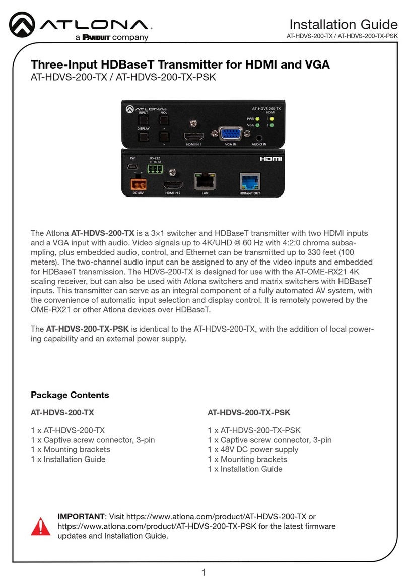
The Atlona AT-HDVS-200-TX-WP is a 2×1 switcher and HDBaseT transmitter with an HDMI input
plus a VGA input with audio. The HDVS-200-TX-WP features a US two-gang, wallplate form
factor. Video signals up to 4K/UHD @ 60 Hz with 4:2:0 chroma subsampling, plus embedded
audio, control, and Ethernet can be transmitted up to 330 feet (100 meters). The two-channel
audio input can be assigned to either video input and embedded for HDBaseT transmission.
The HDVS-200-TX-WP is designed for use with the AT-OME-RX21 4K scaling receiver, but can
also be used with Atlona switchers and matrix switchers with HDBaseT inputs. This transmitter
can serve as an integral component of a fully automated AV system, with the convenience of
automatic input selection and display control. It is remotely powered by the OME-RX21 or other
Atlona devices over HDBaseT.
The Atlona AT-HDVS-200-TX-WP-BLK is identical to the AT-HDVS-200-TX-WP, except for the
addition of interchangeable black and white wallplates and faceplates.
IMPORTANT: Visit https://www.atlona.com/product/AT-HDVS-200-TX-WP or
https://www.atlona.com/product/AT-HDVS-200-TX-WP for the latest rmware updates
and Installation Guide.
1 x AT-HDVS-200-TX-WP
1 x Captive screw connector, 3-pin
1 x Faceplate, w/ LAN port exposed
1 x Installation Guide
1 x AT-HDVS-200-TX-WP-BLK
1 x Captive screw connector, 3-pin
1 x Black faceplate, w/ LAN port exposed
1 x Installation Guide
AT-HDVS-200-TX-WP AT-HDVS-200-TX-WP-BLK
Package Contents

2
Installation Guide
AT-HDVS-200-TX-WP / AT-HDVS-200-TX-WP-BLK
RS-232
RXTX
DISPLAY AUDIO IN
VGA IN
HDMI IN
PWR
LINK
VOL-
INPUT VOL+
FW
Panel Descriptions
5
7 8 10 11
96 12
Front Side Rear
1 3
2
4
1 INPUT
Press this button to toggle between each
of the available inputs: HDMI IN and VGA
IN.
2 DISPLAY
Press this button to turn on/o video
output for the switcher. This button can
also be programmed to send a display
on/o command over CEC, RS-232,
or TCP/IP, to controllable displays or
other connected devices, or send trigger
commands over RS-232 or TCP/IP.
3 PWR
This LED indicator will glow bright green
when the switcher is powered.
4 LINK
This LED indicator will glow bright amber
when a link exists between the AT-
HDVS-200-TX-WP and a PoE-compatible
receiver.
5 VOL+ / VOL-
Press these buttons to increase or
decrease the volume level on the display.
6 FW
Connect a mini USB to USB-A type cable
from this port to a computer to update the
rmware. Refer to the User Manual for
more information.
7 AUDIO IN
Connect a 3.5mm mini-stereo audio cable,
from an analog audio source, to this port.
8 HDMI IN
Connect an HDMI cable from this port to
an HD source.
9 VGA IN
Connect a VGA cable from this port to a
VGA source.
10 HDBaseT
Use an category cable to connect an
HDBaseT PoE-compatible receiver to this
port.
11 Cooling Fan Assembly
Provides active cooling for the switcher by
expelling warm air from the enclosure. To
prevent overheating, make sure this vent
is not blocked.
12 RS-232
Connect the included 3-pin captive-screw
terminal block from this connector to an
RS-232 control device.

3
Installation Guide
AT-HDVS-200-TX-WP / AT-HDVS-200-TX-WP-BLK
RS-232
The AT-HDVS-200-TX-WP / AT-HDVS-200-TX-WP-BLK provides RS-232 control between an
automation system and an RS-232 device. This step is optional and is used when connecting a
computer that is running the control software.
1. Use wire strippers to remove a portion of the cable jacket.
2. Remove at least 3/16” (5 mm) from the insulation of the RX, TX, and GND wires.
3. Insert the TX, RX, and GND wires into correct terminal on the included captive screw block.
If using non-tinned stranded wire, press the orange tab, above the terminal, while inserting
the exposed wire. Repeat this step for the TX, RX, and GND connections.
GND
RX
TX
RX TX GND

4
Installation Guide
AT-HDVS-200-TX-WP / AT-HDVS-200-TX-WP-BLK
Faceplate Removal and Assembly
The AT-HDVS-200-TX-WP / AT-HDVS-200-TX-WP-BLK comes with an additional faceplate, which
allows an Ethernet cable to be connected through the front panel. Removal of the faceplate re-
quires that the AT-HDVS-200-TX-WP / AT-HDVS-200-TX-WP-BLK be removed from the electrical
box or mud ring.
1. Remove the wall plate from the electrical box and slide out the AT-HDVS-200-TX-WP
assembly, as shown. It is recommended that the Ethernet cable, connected to the
HDBaseT port, be disconnected from the AT-HDVS-200-TX-WP, to allow for easy installation
of the new faceplate.
Wall cross-section
FW
AUDIO IN
VGA IN
HDMI IN
DISPLAY
PWR
LINK
VOL-
INPUT VOL+
AUDIO IN
VGA IN
HDMI IN
DISPLAY
PWR
LINK
VOL-
INPUT VOL+
FW
2. Unscrew the hex bolt, next to the HDMI connector on the front panel. Once the hex bolt is
removed, gently remove the faceplate by pulling it toward you.
3. Attach the new faceplate and secure it using the hex bolt.
4. Install the AT-HDVS-200-TX-WP / AT-HDVS-200-TX-WP-BLK into the electrical box or mud
ring. If the Ethernet cable was disconnected from the AT-HDVS-200-TX-WP / AT-HDVS-200-
TX-WP-BLK during disassembly, make sure to reconnect it before reinstalling the unit into
the electrical box.
5. Reattach the wallplate, securing the assembly in place.

5
Installation Guide
AT-HDVS-200-TX-WP / AT-HDVS-200-TX-WP-BLK
RS-232
RXTX
DISPLAY AUDIO IN
VGA IN
HDMI IN
PWR
LINK
VOL-
INPUT VOL+
FW
1. Connect an category cable, up to 230 feet (70 meters), from the HDBaseT port on the
switcher to a PoE-compatible receiver (not included). Category cables should use EIA/TIA-
568B termination. CAT6a/7 solid core cables should be used for best results.
Complete the installation of the AT-HDVS-200-TX-WP into the electrical box or mud ring.
2. Connect an HDMI cable between the HD source and the HDMI IN port on the switcher.
3. Connect a VGA cable from a VGA source to the VGA IN port on the switcher.
4. Connect a 3.5 mm mini-stereo cable from the AUDIO IN port on the switcher to the analog
audio source. The AT-HDVS-200-TX-WP can pass audio either with or without a video
signal. Refer to the User Manual for more information.
5. OPTIONAL: Connect an RS-232 control device to the RS-232 port on the switcher. This
port is used to control functions of the AT-HDVS-200-TX-WP, such as volume up/down,
display on/o, etc.
No power supply is required for the AT-HDVS-200-TX-WP. This unit will be powered over
the category cable, from an HDBaseT receiver.
Refer to the tables below for recommended cabling when using Altona products with HDBaseT.
The number of bars indicate the signal quality when using each type of cable. Higher-quality
signals are represented by more bars.
Core Shielding CAT5e CAT6 CAT6a CAT7
Solid UTP (unshielded) N/A
STP (shielded)
IMPORTANT: Stranded or patch cables are not recommended due to
performance issues.
Installation
Cable Recommendation Guidelines
1
Before Determine the proper faceplate to be used for installation. If using the LAN port, then
refer to Faceplate Removal and Assembly for information on changing the faceplate.
2
3
4
5

6
Installation Guide
AT-HDVS-200-TX-WP / AT-HDVS-200-TX-WP-BLK
Notes

7
Installation Guide
AT-HDVS-200-TX-WP / AT-HDVS-200-TX-WP-BLK
Notes

8
Installation Guide
AT-HDVS-200-TX-WP / AT-HDVS-200-TX-WP-BLK
Version 1 25347-R1
© 2022 Atlona Inc. All rights reserved. “Atlona” and the Atlona logo are registered trademarks of Atlona Inc. All other brand names and trademarks or registered
trademarks are the property of their respective owners. Pricing, specications and availability subject to change without notice. Actual products, product images, and
online product images may vary from images shown here.
English Declaration of Conformity
Warranty
Chinese Declaration of Conformity 中国RoHS合格声明
The English version can be found under the resources tab at:
https://atlona.com/product/at-hdvs-200-tx-wp/.
The English version can be found under the resources tab at:
https://atlona.com/product/at-hdvs-200-tx-wp-blk/.
To view the product warranty, use the following link or QR code:
https://atlona.com/warranty/.
由SKU列出於:
https://atlona.com/about-us/china-rohs/.
The terms HDMI, HDMI High-Denition Multimedia Interface, and the HDMI Logo are trademarks or
registered trademarks of HDMI licensing Administrator, Inc.
US International
atlona.com •408.962.0515 •41.43.508.4321
This manual suits for next models
1
Table of contents
Other Panduit Transmitter manuals
Popular Transmitter manuals by other brands

Lectrosonics
Lectrosonics UM400AV instruction manual

Siemens
Siemens SITRANS P500 Compact operating instructions

Johnson Controls
Johnson Controls P-5219 manual

Honeywell
Honeywell oneWireless XYR 6000 quick start guide

Flexit
Flexit CI 81 Assembly, installation and operation instructions

E+E Elektronik
E+E Elektronik EE375 Series manual