DirekTronik LTC2 User manual

LTC2 - LoRaWAN Temperature Transmitter User
Manual
last modified by Xiaoling
on 2023/02/02 14:47

User Manual for LoRaWAN End Nodes - LTC2 - LoRaWAN Temperature Transmitter User Manual
Table of Contents
1. Introduction ........................................................................................................................................................................ 6
1.1 What is LTC2 LoRaWAN Temperature Transmitter ................................................................................................ 6
1.2 Features ........................................................................................................................................................................ 6
1.3 Applications ................................................................................................................................................................... 7
1.4 Hardware Change log ................................................................................................................................................... 7
1.5 Pin Definitions and Switch .......................................................................................................................................... 7
1.5.1 Jumper JP2 ( Power ON) ..................................................................................................................................... 7
1.5.2 LED .......................................................................................................................................................................... 7
1.5.3 PT100 Interfaces .................................................................................................................................................... 7
1.5.4 Reset Button ........................................................................................................................................................... 7
1.6 Probe Variant ............................................................................................................................................................. 7
2. How to use LTC2? ........................................................................................................................................................... 9
2.1 Connect to PT100 sensors ......................................................................................................................................... 9
2.2 How it works? ............................................................................................................................................................ 9
2.3 Quick guide to connect to LoRaWAN server (OTAA) ............................................................................................. 9
2.4 Uplink Payload ............................................................................................................................................................ 16
2.5 Datalog Feature ......................................................................................................................................................... 17
2.5.1 Unix TimeStamp .................................................................................................................................................. 17
2.5.2 Set Device Time ................................................................................................................................................... 18
2.5.3 Poll sensor value .................................................................................................................................................. 18
2.5.4 Datalog Uplink payload ....................................................................................................................................... 19
2.6 Alarm Mode ................................................................................................................................................................. 21
3. Configure LTC2 via AT Command or LoRaWAN Downlink ...................................................................................... 21
3.1 Set Transmit Interval Time ....................................................................................................................................... 21
3.2 Enable PT100 channels ............................................................................................................................................ 22
3.3 Set External Sensor Mode ........................................................................................................................................ 22
3.4 Quit AT Command ..................................................................................................................................................... 23
3.5 Set system time .......................................................................................................................................................... 23
3.6 Set Time Sync Mode ................................................................................................................................................. 23
3.7 Set Time Sync Interval .............................................................................................................................................. 23
3.8 Retrieve data .............................................................................................................................................................. 24
3.9 Enable Alarm mode ................................................................................................................................................... 24
3.10 Alarm check time ..................................................................................................................................................... 24
3.11 Set Alarm Threshold ................................................................................................................................................ 24
3.12 Set Calibrate Value .................................................................................................................................................. 25
3.13 Poll Calibrate Value ................................................................................................................................................. 25
3.14 Print data entries base on page ............................................................................................................................. 25
3.15 Print last few data entries ....................................................................................................................................... 26
3.16 Clear Flash Record .................................................................................................................................................. 27
4. Battery & How to replace .............................................................................................................................................. 27
4.1 Battery Type ............................................................................................................................................................... 27
4.2 Replace Battery .......................................................................................................................................................... 28
4.3 Power Consumption Analyze ................................................................................................................................... 28
5. Firmware Change Log and Upload Firmware ............................................................................................................. 29
............................................................................................................................................................................................... 29
6. FAQ .................................................................................................................................................................................. 29
6.1 How to use AT Command to configure LTC2 ........................................................................................................ 29
6.2 How to connect a customized PT100 cable? ........................................................................................................ 30
6.3 What is the frequency range of LTC2 LoRa part? ................................................................................................ 33
6.4 How to change the LoRa Frequency Bands/Region ............................................................................................. 34
7. Trouble Shooting ............................................................................................................................................................ 34
7.1 AT Command input doesn't work ............................................................................................................................ 34
8. Order Info ........................................................................................................................................................................ 34
Page 2 / 35 - last modified by Xiaoling on 2023/02/02 14:47

User Manual for LoRaWAN End Nodes - LTC2 - LoRaWAN Temperature Transmitter User Manual
9. Packing Info ..................................................................................................................................................................... 34
10. Support ........................................................................................................................................................................... 35
Page 3 / 35 - last modified by Xiaoling on 2023/02/02 14:47

User Manual for LoRaWAN End Nodes - LTC2 - LoRaWAN Temperature Transmitter User Manual
Table of Contents:
Page 4 / 35 - last modified by Xiaoling on 2023/02/02 14:47

User Manual for LoRaWAN End Nodes - LTC2 - LoRaWAN Temperature Transmitter User Manual
•1. Introduction
•1.1 What is LTC2 LoRaWAN Temperature Transmitter
•1.2 Features
•1.3 Applications
•1.4 Hardware Change log
•1.5 Pin Definitions and Switch
•1.5.1 Jumper JP2 ( Power ON)
•1.5.2 LED
•1.5.3 PT100 Interfaces
•1.5.4 Reset Button
•1.6 Probe Variant
•2. How to use LTC2?
•2.1 Connect to PT100 sensors
•2.2 How it works?
•2.3 Quick guide to connect to LoRaWAN server (OTAA)
•2.3.1 Step 1: Create a device in TTN with the OTAA keys from LTC2
•2.3.2 Step 2: Power on LTC2
•2.4 Uplink Payload
•BAT
•Status & EXT
•Channel1 data and Channel 2 data
•Unix TimeStamp
•2.5 Datalog Feature
•2.5.1 Unix TimeStamp
•2.5.2 Set Device Time
•2.5.3 Poll sensor value
•2.5.4 Datalog Uplink payload
•2.6 Alarm Mode
•3. Configure LTC2 via AT Command or LoRaWAN Downlink
•3.1 Set Transmit Interval Time
•3.2 Enable PT100 channels
•3.3 Set External Sensor Mode
•3.4 Quit AT Command
•3.5 Set system time
•3.6 Set Time Sync Mode
•3.7 Set Time Sync Interval
•3.8 Retrieve data
•3.9 Enable Alarm mode
•3.10 Alarm check time
•3.11 Set Alarm Threshold
•3.12 Set Calibrate Value
•3.13 Poll Calibrate Value
•3.14 Print data entries base on page
•3.15 Print last few data entries
•3.16 Clear Flash Record
•4. Battery & How to replace
•4.1 Battery Type
•4.2 Replace Battery
•4.3 Power Consumption Analyze
•5. Firmware Change Log and Upload Firmware
•
•6. FAQ
•6.1 How to use AT Command to configure LTC2
•6.2 How to connect a customized PT100 cable?
•6.3 What is the frequency range of LTC2 LoRa part?
•6.4 How to change the LoRa Frequency Bands/Region
•7. Trouble Shooting
•7.1 AT Command input doesn't work
•8. Order Info
•9. Packing Info
Page 5 / 35 - last modified by Xiaoling on 2023/02/02 14:47
User Manual for LoRaWAN End Nodes - LTC2 - LoRaWAN Temperature Transmitter User Manual
•10. Support
1. Introduction
1.1 What is LTC2 LoRaWAN Temperature Transmitter
The Dragino LTC2 Industrial LoRaWAN Temperature Transmitter is designed to monitor temperature for different
environment. It supports to read PT100 probe and convert the value to temperature and uplink to IoT server via
LoRaWAN protocol.
LTC2 supports Datalog feature. User can retrieve the sensor value via LoRaWAN downlink command.
LTC2 is powered by 8500mA Li-SOCI2 battery for long time measurement. The battery can run 2~10 years
depends on the network environment and working mode.
Each LTC2 has two internal 24-bit ADC interfacesand are calibrated on 12 set resistors to make sure the
accuracy measurement on wide range.
LTC2 is LoRaWAN v1.0.3 compatible. Each LTC2 is pre-load with a set of unique keys for LoRaWAN registration,
register these keys to local LoRaWAN server and it will auto connect after power on.
1.2 Features
Page 6 / 35 - last modified by Xiaoling on 2023/02/02 14:47

User Manual for LoRaWAN End Nodes - LTC2 - LoRaWAN Temperature Transmitter User Manual
• LoRaWAN v1.0.3 Class A
• max: 2 x monitor temperature channels
• Support 3 -wire PT-100
• 8500mAh Li-SOCI2 Battery
• Firmware upgrade via console
• Wall Mountable
• Configurable via LoRa or UART
• Datalog and retrieve via LoRaWAN
• Use pre-load PT100 probe or 3rd PT100 probe
• Factory calibration for different resistance range
• Support accuracy measure of resistance and upload
• Battery Monitoring and upload
• Operation Temperature: -40 ~ 65 ℃
1.3 Applications
• Logistics and Supply Chain Management
• Food management
• Cold chains solution
• Industrial Monitoring and Control
1.4 Hardware Change log
LTC2 v1.0: Release.
1.5 Pin Definitions and Switch
1.5.1 Jumper JP2 ( Power ON)
Put a jumper on JP2 will power on the LTC2.
1.5.2 LED
The LED will flash in below case.
1. Send an uplink packet
1.5.3 PT100 Interfaces
There are two independent channels to connect 2 x PT100 probes.
Each channel has 3-wire connection for 3-wire PT100 probes.
1.5.4 Reset Button
Press this button will reboot the LTC2
1.6 Probe Variant
LTC2 provide default probe version. See below for the variant:
Model Photo Description
Page 7 / 35 - last modified by Xiaoling on 2023/02/02 14:47

User Manual for LoRaWAN End Nodes - LTC2 - LoRaWAN Temperature Transmitter User Manual
LTC2-SI Standard IP68 Probe Version
• LTC2 with 1 x Standard IP68 PT100 probe.
• Installation: Insert
• Cable Length : 2m
• PT100 Class : Class A
• Probe Dimension: 4*30mm
• Measure Range: -50 ~ 200 °C
• Suitable Environment: General environment
LTC2-LT Low Temperature Version
• LTC2 with 1 x Low Temperature PT100 probe.
• Installation: Insert
• Cable Length : 2m
• PT100 Class : Class A
• Probe Dimension: 4*30mm
• Measure Range: -196 ~ 150 °C
• Suitable Environment: Low temperature measurement, such as COVID vaccine
transport
LTC2-FS Food Safety Version
• LTC2 with 1 x Food Safety PT100 probe.
• Installation: Insert
• Cable Length : 2m
• PT100 Class : Class A
• Probe Dimension: 4*150mm
• Measure Range: -50 ~ 200 °C
• Suitable Environment: Food temperature measurement
LTC-FSA Food Safety Version
• LTC2 with 1 x Food Safety PT100 probe.
• Installation: Insert
• Cable Length : 2m
• PT100 Class : Class A
• Probe Dimension: 4*150mm
• Measure Range: -50 ~ 200 °C
• Suitable Environment: Food temperature measurement
LTC2-FT Flat Type Version
• LTC2 with 1 x Flat Type PT100 probe.
• Installation: Attached
• Cable Length : 2m
• PT100 Class : Class A
• Probe Dimension: 8*25mm
• Measure Range: -50 ~ 200 °C
• Suitable Environment: Attached to the measure point.
Page 8 / 35 - last modified by Xiaoling on 2023/02/02 14:47

User Manual for LoRaWAN End Nodes - LTC2 - LoRaWAN Temperature Transmitter User Manual
LTC2-HT High Temperature Version
• LTC2 with 1 x high temperature PT100 probe.
• Installation: Insert
• Cable Length : 3m
• PT100 Class : Class A
• Probe Dimension: 4*30mm
• Measure Range: -70 ~ 550 °C
Suitable Environment: High Temperature
LTC2-NA No Probe version:
• User can connect to their own PT100 Probe
• Grand Hole: M12
• Suitable Environment:
Connect to customized probe
2. How to use LTC2?
2.1 Connect to PT100 sensors
LTC2 has different probe option provided for ordering, if user has LTC2 with probe, just skip this step. If user want
to connect to a 3rd party PT100 probe, please see CONNECT A 3rdPARTY PT100 probe.
2.2 How it works?
The LTC2 is working in LoRaWAN OTAA Class A mode. Each LTC2 is shipped with a worldwide unique set of
OTAA and ABP keys. User needs to input the OTAA or ABP keys in the LoRaWAN network server so to register.
LTC2 will join the LoRaWAN network and start to transmit data. The default period for each uplink is 20 minutes.
On each uplink, LTC2 will check its two ADC Interfaces and get the temperature from the sensor and send out to
server.
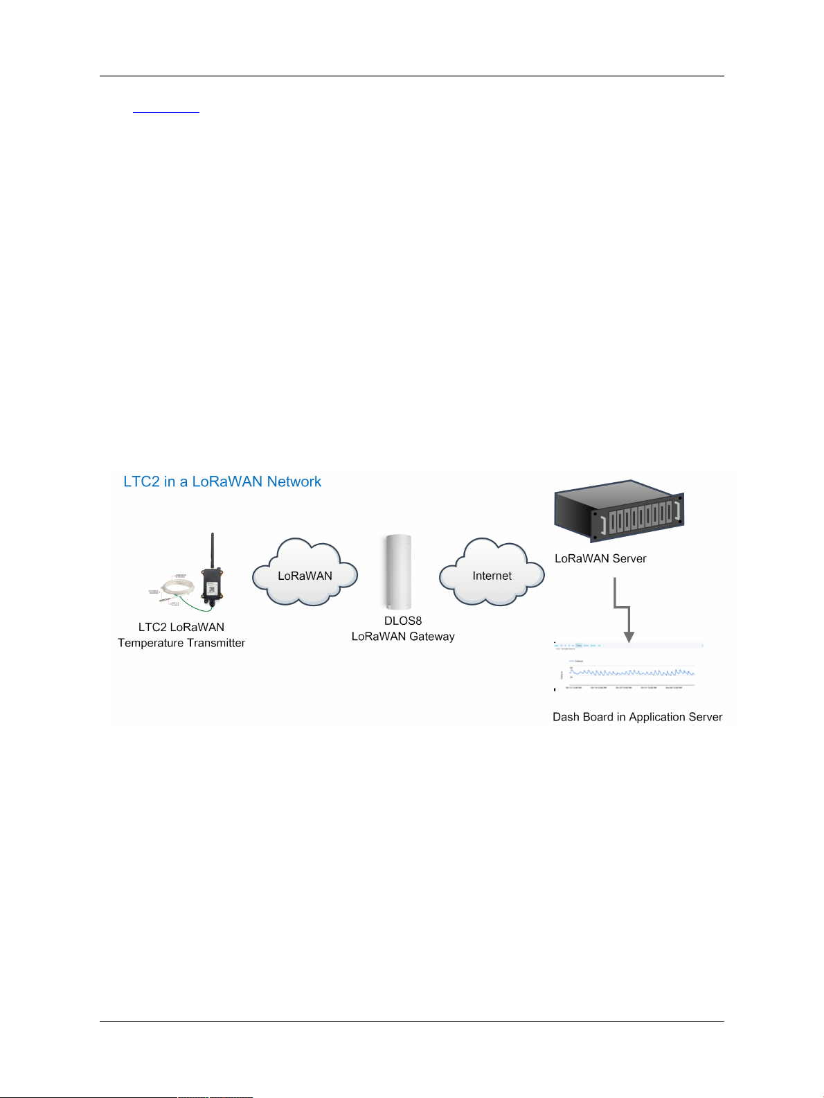
2.3 Quick guide to connect to LoRaWAN server (OTAA)
Here is an example for how to join the TTN v3 LoRaWANServer. Below is the network structure, in this demo we
use DLOS8 as LoRaWAN gateway.
Page 9 / 35 - last modified by Xiaoling on 2023/02/02 14:47
User Manual for LoRaWAN End Nodes - LTC2 - LoRaWAN Temperature Transmitter User Manual
The DLOS8 is already set to connect to TTN. Rest we need to is register the LTC2 to TTN v3:
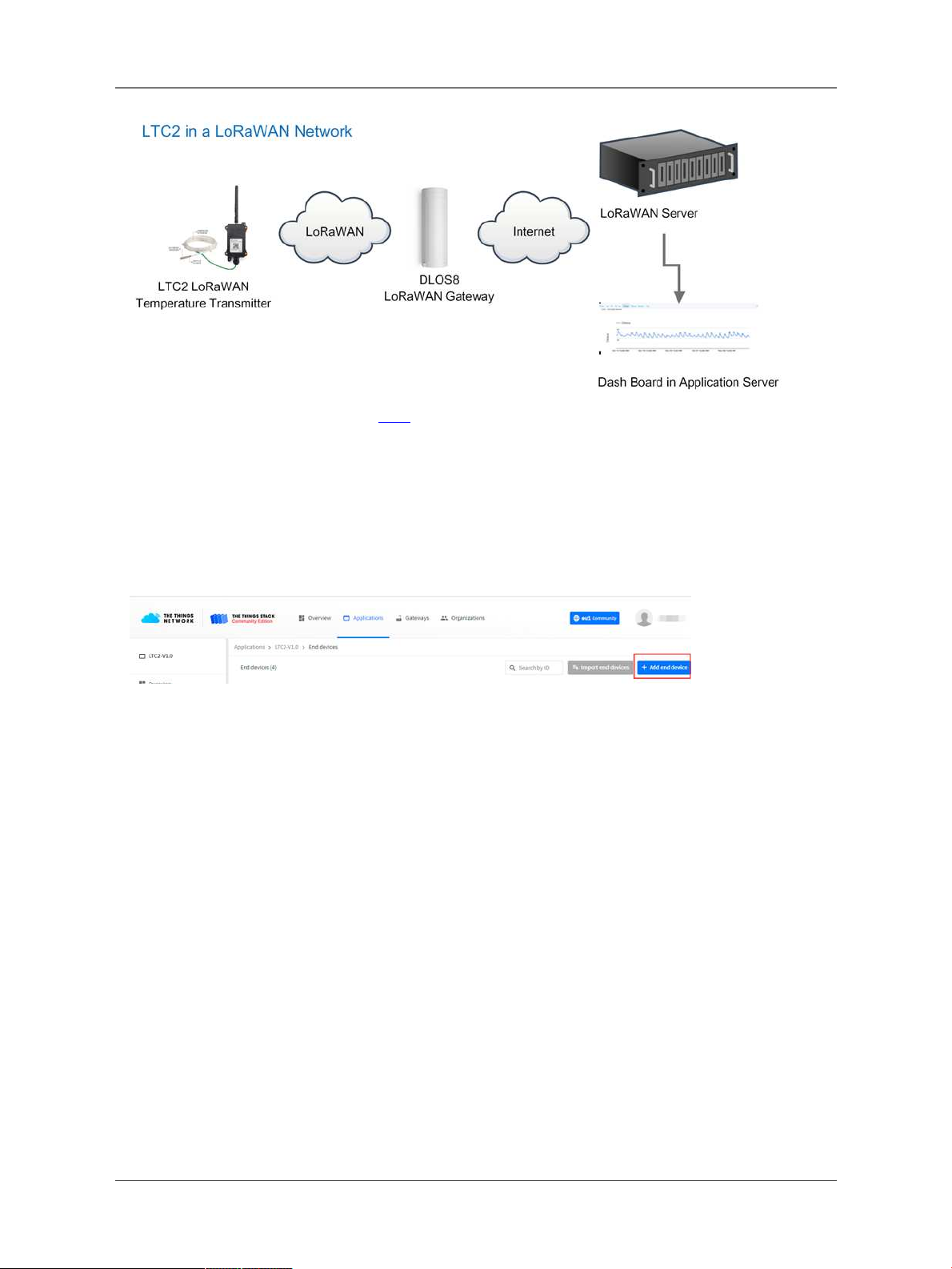
2.3.1 Step 1: Create a device in TTN with the OTAA keys from LTC2
Below is TTN screen shot:
• Create Application first.
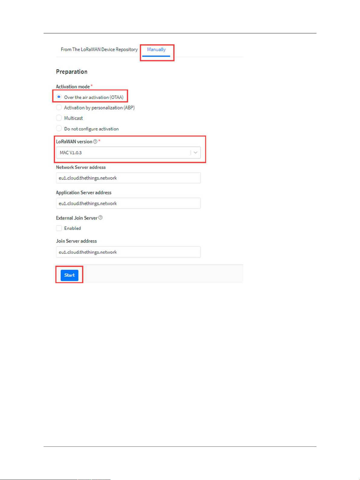
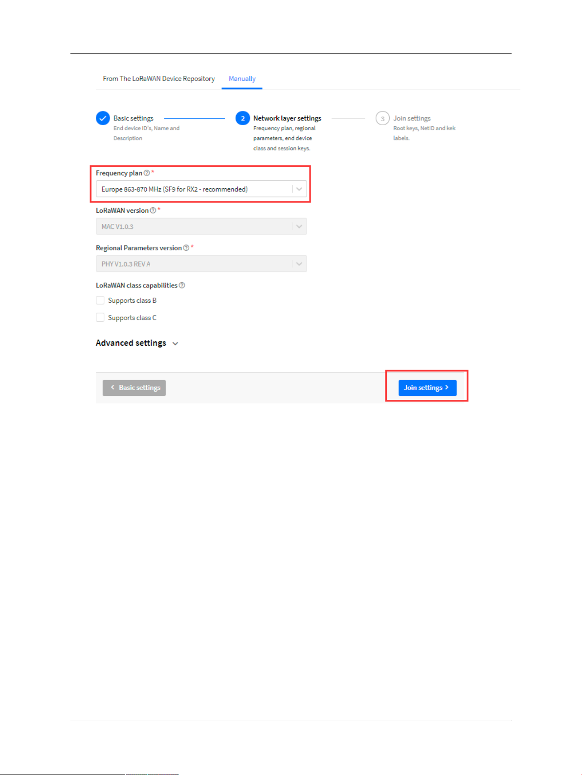
• Manually Add a LoRaWAN End Device device. Choose OTAA and MAC v1.0.3
Page 10 / 35 - last modified by Xiaoling on 2023/02/02 14:47
User Manual for LoRaWAN End Nodes - LTC2 - LoRaWAN Temperature Transmitter User Manual
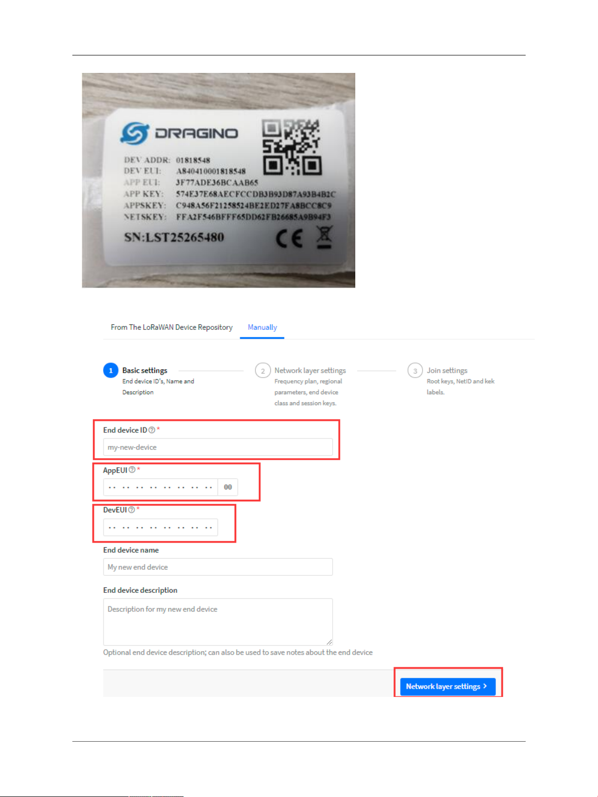
Input the OTAA keys for LTC2.
Each LTC2 is shipped with a sticker with the default device EUI as below:
Page 11 / 35 - last modified by Xiaoling on 2023/02/02 14:47
User Manual for LoRaWAN End Nodes - LTC2 - LoRaWAN Temperature Transmitter User Manual
•Input these keys to device portal.
•Choose the Frequency band for this end node.
Page 12 / 35 - last modified by Xiaoling on 2023/02/02 14:47
User Manual for LoRaWAN End Nodes - LTC2 - LoRaWAN Temperature Transmitter User Manual
•Input APP Key in this page as well.
Page 13 / 35 - last modified by Xiaoling on 2023/02/02 14:47

User Manual for LoRaWAN End Nodes - LTC2 - LoRaWAN Temperature Transmitter User Manual
Add payload formatter So TTNv3 knows how to parse the LTC2 upload value.
The payload for TTN can be found at below link:ttps://github.com/dragino/dragino-end-node-decoder
2.3.2 Step 2: Power on LTC2
Page 14 / 35 - last modified by Xiaoling on 2023/02/02 14:47
User Manual for LoRaWAN End Nodes - LTC2 - LoRaWAN Temperature Transmitter User Manual
LTC2 is power off when ship from factory.
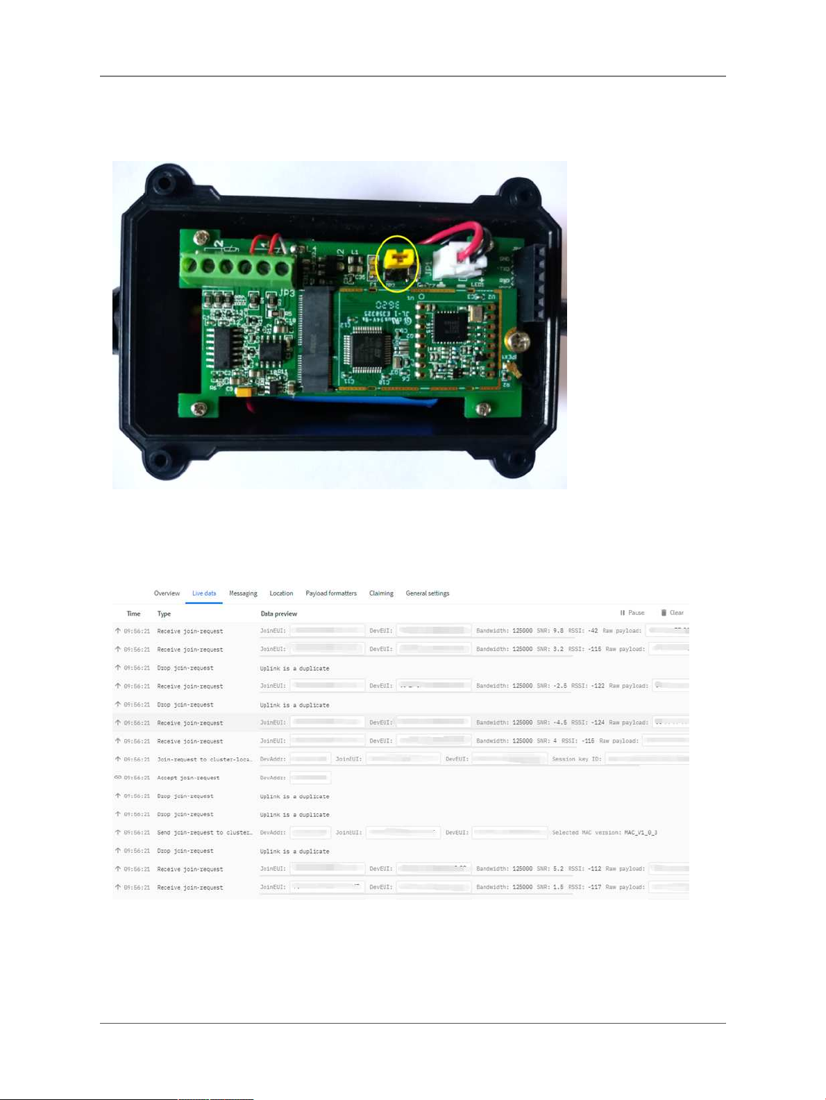
Put a Jumper on JP2 to power on the device.
After power on, LTC2 will auto join to TTN network via the LoRaWAN coverage by DLOS8. After join success,
LTC2 will start to update message to IoT server.
Below is an example uplink message which shows the LTC2 is sending Join Request to TTNv3.
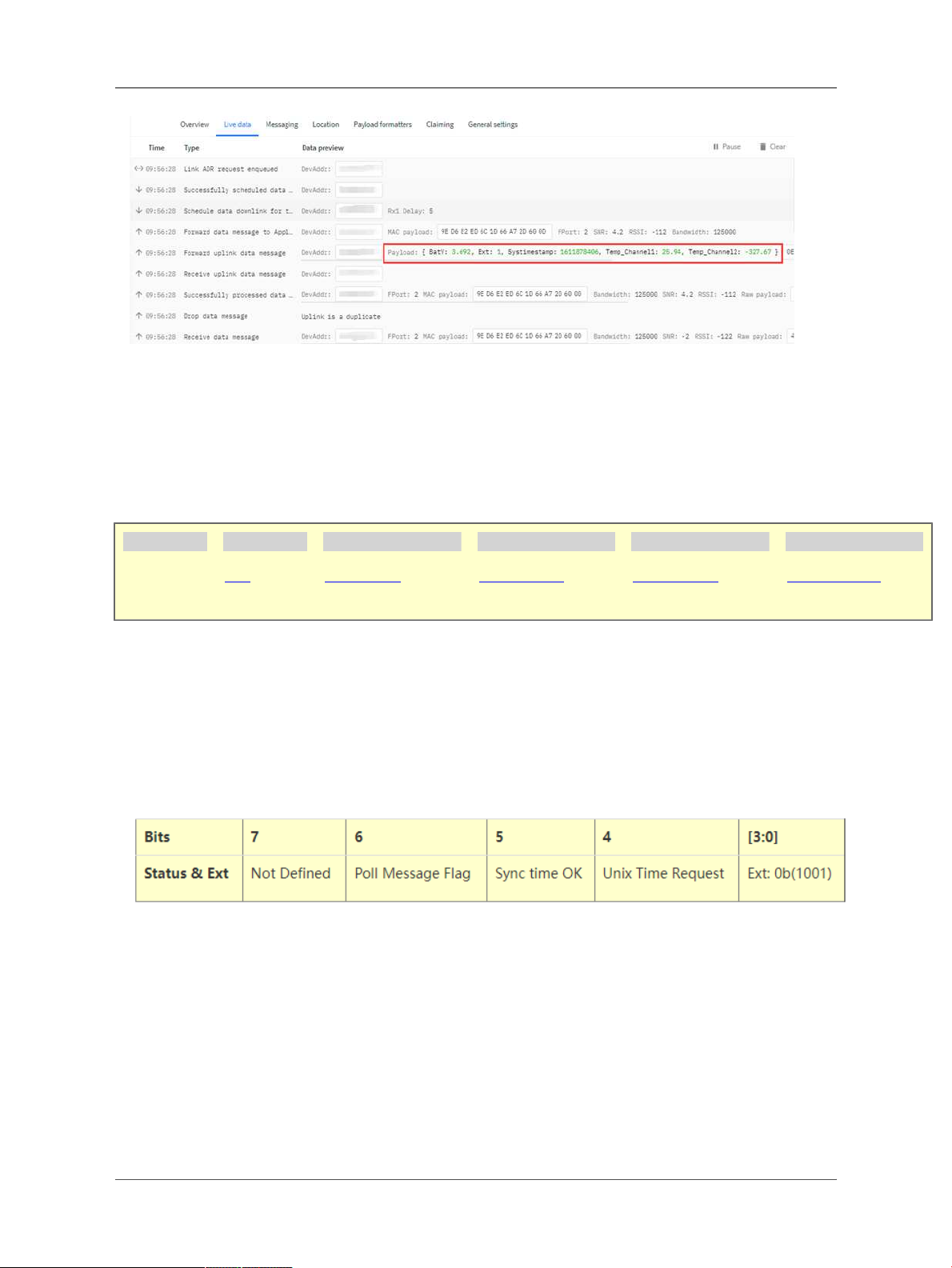
After join successful, LTC2 will send uplink message with the sensor value.
Page 15 / 35 - last modified by Xiaoling on 2023/02/02 14:47
User Manual for LoRaWAN End Nodes - LTC2 - LoRaWAN Temperature Transmitter User Manual
Above value shows Channel1 detect 25.94 degree. There is no PT100 connected on Channel 2, so it shows
-327.67.
2.4 Uplink Payload
Below is the uplink payload which shows
Size(bytes) 2 1 2 2 4
Value BAT
Status & EXT Channel 1 data Channel 2data Unix TimeStamp
BAT
Ex1: 0x0E3C ⇒ 3644 (mV) = 3.644 V
Status & EXT
•Poll Message Flag: 1: This message is a poll message reply, 0: means this is a normal uplink.
•Sync time OK: 1: Set time
ok,0: N/A. After time SYNC request is send, device will set this bit to 0
until got the time stamp from application server.
•Unix Time Request: 1: Request server downlink Unix time, 0 : N/A. In this mode, LTC2 will set this bit to 1
every 10 day to request a time SYNC. (AT+SYNCMOD to set this)
•EXT: The decode method for Channel 1 data and Channel 2 data
• 0b(0001): Upload PT100 temperature, with 2 decimals, range: -327.67 ~ 327.67 ℃
• 0b(0010): Upload PT100 temperature, with 1 decimals, range:-3276.7 ~ 3276.7 ℃
• 0b(0011): Upload Resistance instead of Temperature, range: -327.67~ 327.67 ohm
Page 16 / 35 - last modified by Xiaoling on 2023/02/02 14:47

User Manual for LoRaWAN End Nodes - LTC2 - LoRaWAN Temperature Transmitter User Manual
Channel1 data and Channel 2 data
Unix TimeStamp
Refer to Datalog feature.
Example Uplink Payload:
Uplink payload example 1: 0CE9011422EC2D6073E83B
• Bat voltage:0x0CE9 =3305mV
• Ext=0x01
• Channel1 temp=0x1422/100=51.54 ℃
• Channel2 temp=(0xEC2D-65536)/100=-50.75 ℃
• System timestamp=0x6073E83B= 1618208827(UTC)
If payload is: EC2DH : (EC2D & 8000 == 1) , temp = (EC2DH - 65536)/100 = -50.75 ℃
(EC2D & 8000:Judge whether the highest bit is 1, when the highest bit is 1, it is negative)
Uplink payload example 2: 0CED020203FE056073E697
• Bat voltage:0x0CED =3309mV
• Ext=0x02
• Channel1 temp=0x0203/10=515.4 ℃
• Channel2 temp=(0xFE05-65536)/10=-507.5 ℃
• System timestamp=0x6073E697=1618208407(UTC)
If payload is: FE05H : (FE05 & 8000 == 1) , temp = (FE05H - 65536)/100 = 507.5 ℃
(EC2D & 8000:Judge whether the highest bit is 1, when the highest bit is 1, it is negative)
Uplink payload example 3 : 0CE9032EDE1F406073E967
• Bat voltage:0x0CE9 =3305mV
• Ext=0x03
• Channel1 res=0x2EDE/100=119.98 ohm
• Channel2 res=0x1F40/100=80.00 ohm
• System timestamp=0x6073E967= 1618209127(UTC)
2.5 Datalog Feature
LTC2 will auto get the time from LoRaWAN server during Join, and each uplink will then include a timestamp.
When user want to retrieve sensor value, user can send a poll command from the IoT platform to ask sensor to send
value in the required time slot.
2.5.1 Unix TimeStamp
Page 17 / 35 - last modified by Xiaoling on 2023/02/02 14:47

User Manual for LoRaWAN End Nodes - LTC2 - LoRaWAN Temperature Transmitter User Manual
LTC2 uses Unix TimeStamp format based on
Users can get this time from the link: https://www.epochconverter.com/ :
Below is the converter example
So, we can use AT+TIMESTAMP=1611889405 or downlink 3060137afd00 to set current time 2021 – Jan -- 29
Friday 03:03:25
2.5.2 Set Device Time
There are two ways to set the device's time:
1. Through LoRaWAN MAC Command (Default settings)
Users need to set SYNCMOD=1 to enable sync time via the MAC command.
Once LTC2 Joined LoRaWAN network, it will send the MAC command (DeviceTimeReq) and server will reply
with (DeviceTimeAns) to send the current time to LTC2. If LTC2 fails to get the time from server, LTC2 will use the
internal time and wait for next time request (AT+SYNCTDC to set time request period, default is 10 days).
Note: LoRaWAN Server needs to support LoRaWAN v1.0.3(MAC v1.0.3)or higher to support this MAC command
feature, Chirpstack,TTNv3 and loriot support but TTN v2 doesn't support. If server doesn't support this command,
it will through away uplink packet with this command, so user will lose the packet with time request for TTN v2 if
SYNCMOD=1.
2. Manually Set Time
Users need to set SYNCMOD=0 to manual time, otherwise, the user set time will be overwritten by the time set by
the server.
2.5.3 Poll sensor value
Page 18 / 35 - last modified by Xiaoling on 2023/02/02 14:47
User Manual for LoRaWAN End Nodes - LTC2 - LoRaWAN Temperature Transmitter User Manual
Users can poll sensor values based on timestamps. Below is the downlink command.
Downlink Command to poll Open/Close status (0x31)
1byte 4bytes 4bytes 1byte
31 Timestamp start Timestamp end Uplink Interval
Timestamp start and Timestamp end use Unix TimeStamp format as mentioned above. Devices will reply with all
data log during this time period, use the uplink interval.
For example, downlink command
Is to check 2021/5/16 01:00:00 to 2021/5/16 02:00:00's data
Uplink Internal =10s,means LTC2 will send one packet every 10s. range 5~255s.
2.5.4 Datalog Uplink payload
When server senser a datalog polling to LTC2, LTC2 will reply with one or more uplink messages as reply. Each
uplink message includes multiply data entries value. Each entry has the same payload format asnormal uplink
payload.
Note:
• Poll Message Flag is set to 1.
• Each data entry is 11 bytes, to save airtime and battery, devices will send max bytes according to the current
DR and Frequency bands.
For example, in US915 band, the max payload for different DR is:
1. DR0:max is 11 bytes so one entry of data
2. DR1: max is 53 bytes so devices will upload 4 entries of data (total 44 bytes)
3. DR2: total payload includes 11 entries of data
4. DR3: total payload includes 22 entries of data.
If devise doesn't have any data in the polling time. Device will uplink 11 bytes of 0
Example:
If LTC2 has below data inside Flash:
Page 19 / 35 - last modified by Xiaoling on 2023/02/02 14:47
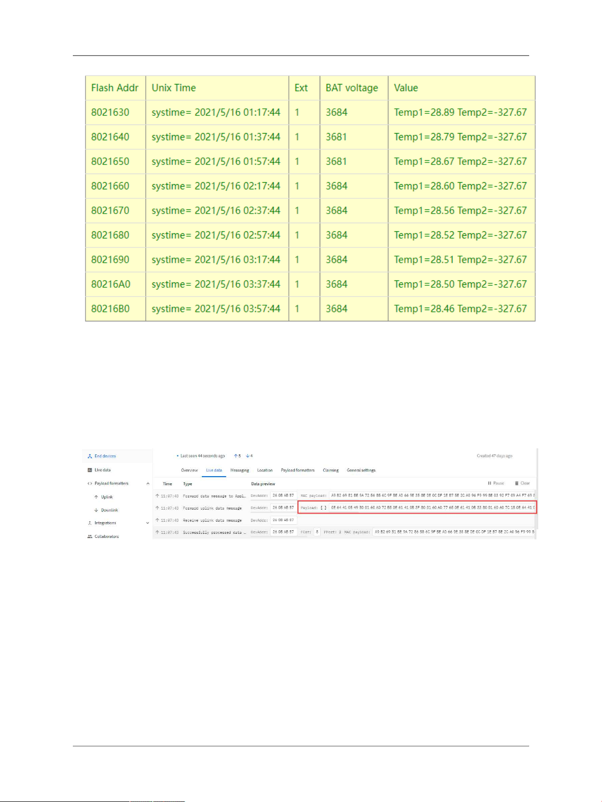
User Manual for LoRaWAN End Nodes - LTC2 - LoRaWAN Temperature Transmitter User Manual
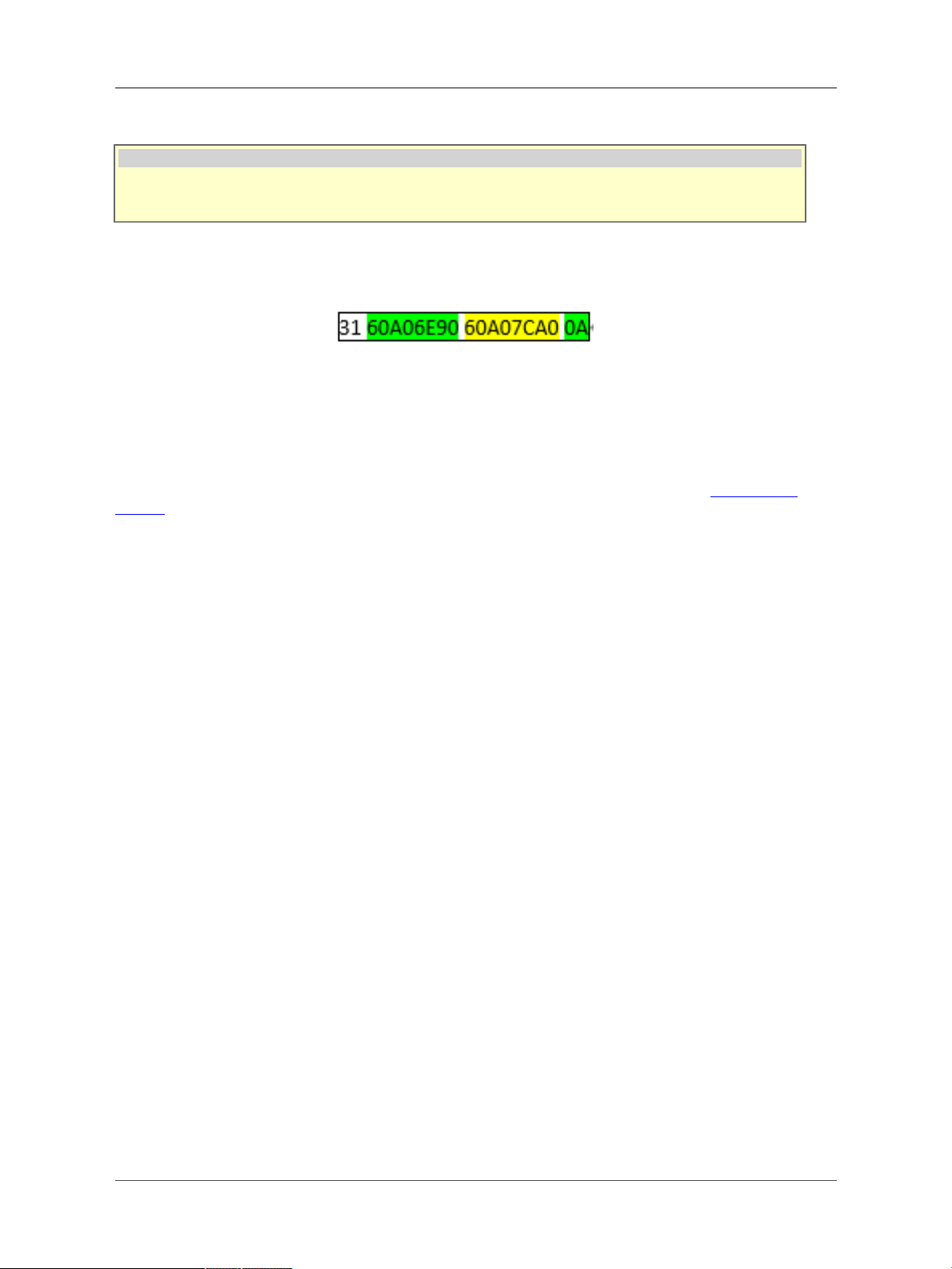
If user send below downlink command:
3160A06E9060A098C00A
Where : Start time: 60A06E90 = time 21/5/16 01:00:00
Stop time: 60A098C0 = time 21/5/16 04:00:00
LTC2 will uplink this payload.
0E64410B49800160A072B80E61410B3F800160A077680E61410B33800160A07C180E64410B2C800160A080C80E64410B28800160A085780E64410B24800160A08A280E64410B23800160A08ED80E64410B22800160A093880E64410B1E800160A09838
Where the first 11 bytes is for the first entry:
0E64410B49800160A072B8
Bat voltage:0x0E64 =3684mV
poll message flag & Ext=0x41,means reply data,Ext=1
Channel1 temp=0x0B49/100=28.89℃
Channel2 temp=0x8001/100=-327.67℃
System timestamp=0x60A072B8= 1621127864(UTC)
Page 20 / 35 - last modified by Xiaoling on 2023/02/02 14:47
Table of contents
Popular Transmitter manuals by other brands


Endress+Hauser
Endress+Hauser Proline 300 Modbus RS485 Brief operating instructions

Omnitronic
Omnitronic WAMS-08BT user manual

Rohde & Schwarz
Rohde & Schwarz SU 4200 operating manual

Omega
Omega EWS-BP-A user guide

Sekonic
Sekonic RT-20PW operating manual

BWI Eagle
BWI Eagle AIR-EAGLE XLT Product information bulletin

Dometic
Dometic Waeco PerfectView VT100DIG Installation and operating manual

Bacharach
Bacharach GDX-350 instructions

Marshall Radio Telemetry
Marshall Radio Telemetry PowerMax user guide

Texas Instruments
Texas Instruments FlatLink SN75LVDS83B user guide

S+S Regeltechnik
S+S Regeltechnik PREMASGARD SHD652 Operating Instructions, Mounting & Installation

GHM
GHM DeltaOHM BAROsense operating manual