TESTO 6651 User manual

testo 6651 Ethernet · Humidity transmitters
testo 6600 · Probes
P2A software · Parameterizing, adjusting and analyzing
software
Instruction manual Volume 1 en
1.888.610.7664info@Testo-Direct.com www.Testo-Direct.com

2 Safety and the environment
Safety and the environment
Avoiding electrical hazards
►Never use the instrument and connected probes to measure on or near
live parts!
►Damaged mains cables must only be replaced by authorized personnel.
►Only have the transmitter wired and connected by authorized personnel
with the voltage disconnected.
►You must always comply with the regulations applicable in your country
to the opening and repair of electrical equipment.
Avoiding personal injury/damage to equipment
►Installation, setting and calibration work must only be carried out by
qualified and authorized personnel!
►Only open the instrument when this is expressly described in the
instruction manual for installation, maintenance or repair purposes.
►Observe the permissible storage, transport and operating temperatures.
►Never store or operate the product with solvents and do not use any
desiccants.
►Do not use the instrument for control purposes at the same time as
operating or servicing the transmitter.
►Only operate the product properly, for its intended purpose and within the
parameters specified in the technical data. Do not use force.
►Carry out only the maintenance and repair work that is described in the
documentation. Follow the prescribed steps when doing so. Use only
OEM spare parts from Testo.
Any additional work must only be carried out by authorized personnel.
Otherwise Testo will not accept any responsibility for the proper functioning of
the instrument after repair and for the validity of certifications.
Protecting the environment
►Send the product back to Testo at the end of its useful life. We will
ensure that it is disposed of in an environmentally friendly manner.
1.888.610.7664info@Testo-Direct.com www.Testo-Direct.com

About this document 3
About this document
►Please read this documentation through carefully and familiarize yourself
with the product before putting it to use. Keep this document to hand so
that you can refer to it when necessary. Hand this documentation on to
any subsequent users of the product.
►The following conventions are followed in this document:
Character/
display:
Explanation/example
With the signal word Warning!:
Warns against hazards which could result in serious physical
injury if the precautionary measures indicated are not taken,
e.g.:
De-energize the mains connection before connecting the
transmitter!
With the signal word Caution!:
Warns against hazards which could result in minor physical
injury or damage to equipment if the precautionary
measures indicated are not taken, e.g.:
Observe the permissible operating temperature!
Important information, e.g.:
Administrator rights are required to install the program under
Windows®2000, XP and Vista.
Aim of action, e.g.:
Assembling the instrument at the process
connection:
Requirement that must be met, e.g.:
USB drivers are installed.
1.888.610.7664info@Testo-Direct.com www.Testo-Direct.com

4 About this document
1 Steps are numbered if a certain sequence of actions must
be followed, e.g.:
1Loosen and remove housing screws.
2Remove the upper part of housing.
A step is not numbered if there are no further steps or if the
step is optional, e.g.:
▪Insert probe connector into socket of testo 6651 until
it engages.
" ... " Example entries are in inverted commas, e.g.:
The value "0" results in ....
Bold type Elements of the program interface or instrument display,
e.g.:
The instrument designation appears in the
instrument/parameter file list.
Select Main Menu Channel 1 and confirm with SET.
…>… Functions/paths within a menu, e.g.:
Start > All Programmes > Testo > Transmitter Software.
[ ] Buttons which start an action, e.g.:
Confirm the software key with [OK].
CAPITAL
LETTERS Keys on the instrument or keypad, e.g.:
Press ESC.
1.888.610.7664info@Testo-Direct.com www.Testo-Direct.com

Contents 5
Contents
1TRANSMITTER............................................................................................7
1.1 Specifications........................................................................................... 7
1.1.1 Functions and use.......................................................................7
1.1.2 Scope of delivery ........................................................................7
1.1.3 Accessories.................................................................................8
1.1.4 Technical data.............................................................................8
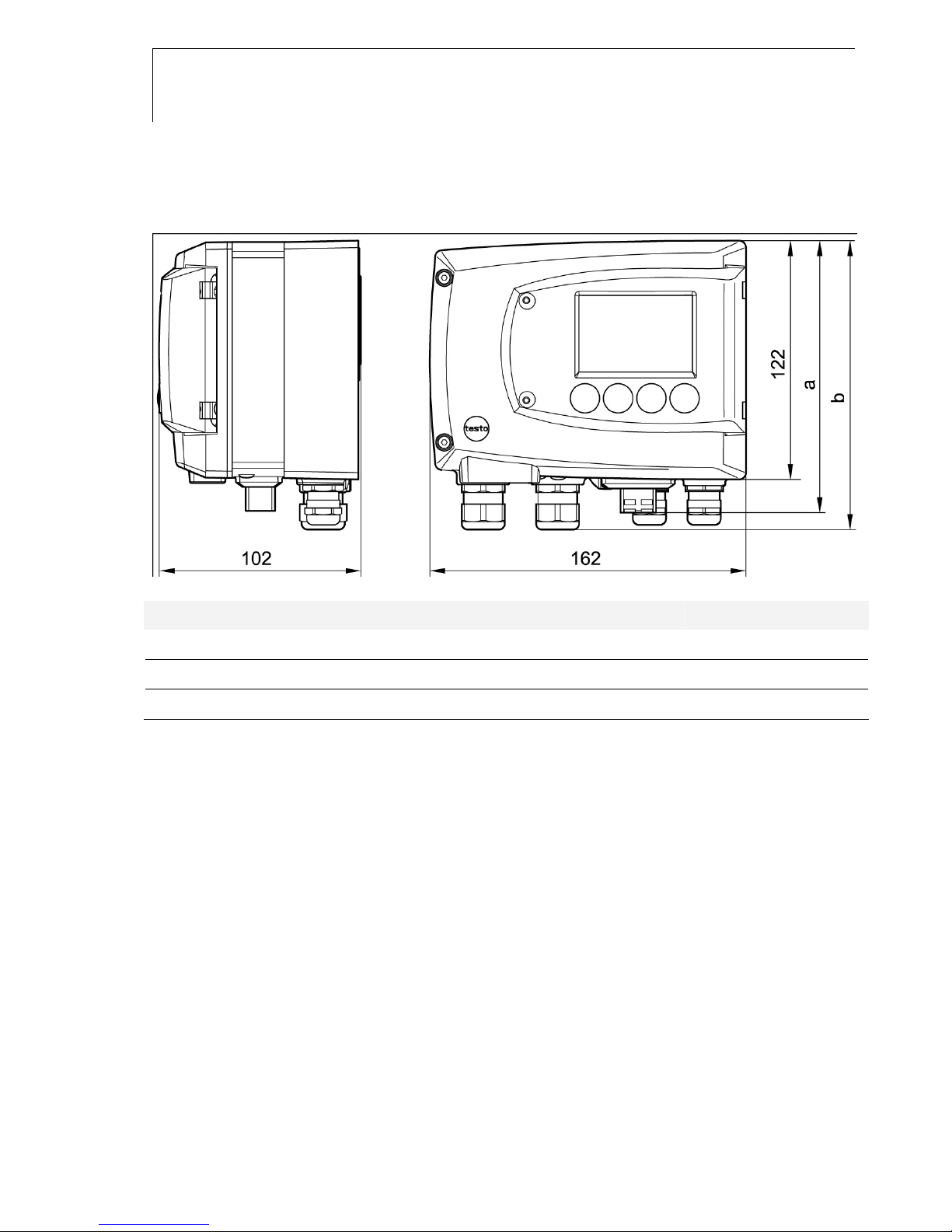
1.1.5 Dimensions ...............................................................................10
1.2 Product description ................................................................................11
1.2.1 At a glance ................................................................................11
1.2.2 Usable probes...........................................................................12
1.2.3 Display and keypad...................................................................13
1.2.4 Service interface .......................................................................13
1.2.5 Relay board (option) .................................................................13
1.2.6 Analog outputs ..........................................................................13
1.2.7 Parameters ...............................................................................14
1.2.8 Scaling ......................................................................................14
1.2.9 Alarm handling ..........................................................................16
1.3 Commissioning ......................................................................................17
1.3.1 Insert Ethernet module (Order no. 0554 6656).........................17
1.3.2 Assembling the instrument .......................................................19
1.3.3 Connecting the instrument........................................................22
1.3.4 Ethernet communication ...........................................................35
1.3.5 Adjusting the instrument ...........................................................53
1.4 Operation ...............................................................................................60
1.4.1 Relationship between user menu and mini-DIN socket is active
..................................................................................................60
1.4.2 Key cover ..................................................................................60
1.4.3 Password protection .................................................................61
1.4.4 Structure of user menu .............................................................62
1.4.5 Overview of the testo 6651 user menu ...........................................63
1.4.6 The individual main menus .......................................................65
1.5 Status, warning and error messages..................................................... 76
1.5.1 Transmitter status messages....................................................76
1.5.2 Transmitter warning messages.................................................77
1.5.3 Transmitter error messages......................................................79
1.5.4 Handling alarm messages ........................................................80
1.5.5 Namur fault conditions ..............................................................81
1.888.610.7664info@Testo-Direct.com www.Testo-Direct.com

6 Contents
1.6 Maintenance and cleaning..................................................................... 82
1.6.1 Maintaining the instrument........................................................ 82
1.6.2 Cleaning the instrument............................................................82
1.888.610.7664info@Testo-Direct.com www.Testo-Direct.com

testo 6651 Ethernet - 1.1 Specifications 7
1 Transmitter
1.1 Specifications
1.1.1 Functions and use
The testo 6651 humidity transmitter is used in conjunction with plug-in,
adjusted probes from the testo 6600 range.
Please refer to volume 2, chapter 2, page 88 for information
about commissioning, operating and maintaining the
testo 6600 probe.
The testo 6651 humidity transmitter is suitable for the following applications,
for example:
Process instrumentation
Clean rooms
Test benches
Drying processes
Production and storage air quality
Complex room climate applications.
In addition to the signal transmission of the readings to a control unit via
analog outputs, the measurement data can simultaneously be recorded,
documented and visualized via Ethernet. Furthermore, it is possible to issue
an alarm for those responsible for the process, if necessary.
1.1.2 Scope of delivery
The scope of delivery of the testo 6651 humidity transmitter includes the
following:
Key cover
Rear panel bracket
Ethernet module
CD-ROM with catalogue files (PDF) and P2A update (this can only be
used in conjunction with the P2A software, which has to be ordered
separately).
1.888.610.7664info@Testo-Direct.com www.Testo-Direct.com

8 testo 6651 - 1.1 Specifications
1.1.3 Accessories
The following accessories are available for the testo 6651 humidity
transmitter:
Protection caps for probes
Mains unit
P2A software (parameterizing, adjusting and analyzing software)
Assembly accessories.
Information about accessories and their order numbers can
be found in volume 2, chapter 4.2, page 149 or on the
website at www.testo.com.
1.1.4 Technical data
Parameters
- Humidity (% RH/°Ctd/°Ftd)
- Temperature (°C/°F)
Measuring range
- Depends on probe
Accuracy
- Depends on probe
Resolution
- 0.1 % RH or 0.1 °C/0.1 °F
Meas. cycle
- 1/s
Interface
- Mini-DIN for P2A software
(parameterizing and adjusting
software) and handheld testo
400/650
Voltage supply
- 4-wire (separate signal and supply
lines):
20 - 30 V AC/DC,
300 mA power consumption
- 500 Ω(power output)
Analog output
- 0 ... 1 V ± 1.5 mV (4-wire) or
- 0 ... 5 V ± 7,5 mV (4-wire) or
- 0 ... 10 V ± 15 mV (4-wire) or
- 0 ... 20 mA ± 0.03 mA (4-wire) or
- 4 ... 20 mA ± 0.03 mA (4-wire)
Resolution of analog output
- 12 bit
Relay
- 4 relays, 250 V AC/DC, 3 A
(optional)
1.888.610.7664info@Testo-Direct.com www.Testo-Direct.com

testo 6651 - 1.1 Specifications 9
Display
- 2-line LCD with plain text line
(optional)
Housing operating temperature
- - 40 ... 70 °C/-40 to +158 °F, with
display from 0 - 50 °C / 32 to
+122 °F
-With integrated relay: -40 - +60 °C
Operating humidity
- 0...100 %rF
Storage temperature
- - 40 ... 80 °C/-40 to +176 °F
Housing, weight
- Plastic, 675 g/1.49 lb
- Ethernet module: 0.610 kg
Protection class
- IP 65 only if the transmitter is
wired properly (closed cable
entries), Ethernet connector,
Harting PushPull connector and
humidity probe are inserted and/or
sealing plug is inserted.
Directives, standards and tests
-EC Directive: 2004/108/EC
-DIN 14644-4
-EN 61000-6-2 interference
immunity
-EN 61000-6-3 interference
emission
- EN 61326-1+A1+A2
Ethernet module
-Interface:
1 x mini DIN
1 x RJ45 (Ethernet 10 BatesT/100
BaseTX
- LED:
2 x green
Warranty
- Duration: 2 years
-Warranty conditions: See web page
www.testo.com/warranty
1.888.610.7664info@Testo-Direct.com www.Testo-Direct.com

10 testo 6651 - 1.1 Specifications
1.1.5 Dimensions
Dimensions in mm a b
With M 20 cable couplings 144 147
With NPT cable couplings 144 144
With M plug-in connections 143
1.888.610.7664info@Testo-Direct.com www.Testo-Direct.com

testo 6651 - 1.2 Product description 11
1.2 Product description
1.2.1 At a glance
1 Keys (with optional display)
2 Service flap screw connection
(self-locking, 2x)
3 Display (optional)
4 Service flap
5 M 16 x 1.5 screw connection*,
e.g. analog outputs
6 M 16 x 1.5 screw connection*,
e.g. voltage supply
7 Eyelet for measuring point
panel
8 M 20 x 1.5 screw connection*,
e.g. relay R 3 and R 4
9 Earthing/PE connection
10 M 20 x 1.5 screw connection*,
e.g. relay R 1 and R 2
11 Probe connector (testo 6600)
12 Upper part of housing
* Alternatively, NPT cable
couplings or M plug-in
connections are available
A Ethernet module
1 DIP switch
2 Ethernet port
3 LED: LAN connection status
4 LED: Supply
1.888.610.7664info@Testo-Direct.com www.Testo-Direct.com

12 testo 6651 - 1.2 Product description
5 Housing screws (4x)
6 Socket for probe connector
7 Hole for fastening to rear
panel bracket (M3 x 6 screw)
8 Plastic bracket for assembly
on rear panel
1.2.2 Usable probes
The testo 6651 humidity transmitter can be used with the following probes:
probe Article no. Characteristic
testo 6601 0555 6600-L01 Wall probe version; accuracy to ± 1.7 % RH;
temperature range -20 °C to +70 °C/-4 to +158 °F,
Sensor plugged
testo 6602 0555 6600-L02 Duct probe version; accuracy to ± 1.7 % RH;
temperature range -20 °C to +70 °C/-4 to +158 °F,
Sensor plugged
testo 6603 0555 6600-L03 Duct probe version; accuracy to ± 1.7 % RH;
temperature range -30 °C to +120°C/-22 to +248 °F,
Sensor plugged
testo 6604 0555 6600-L04 Cable probe version; accuracy to ± 1.7 % RH;
temperature range -20 °C to +70 °C/-4 to +158 °F,
Sensor plugged
testo 6605 0555 6600-L05 Cable probe version; accuracy to ± 1.7 % RH;
temperature range -30 °C to +120°C/-22 to +248 °F,
Sensor plugged
1.888.610.7664info@Testo-Direct.com www.Testo-Direct.com

testo 6651 - 1.2 Product description 13
1.2.3 Display and keypad
The display option allows the testo 6651 humidity transmitter to be operated
via the display and four keys.
The LCD display consists of two 7-segment lines for displaying readings and
units and of an information line (for status messages, for example).
The brightness and contrast of the display and the background lighting
(permanent or off) can be changed via the user menu or the P2A software.
1.2.4 Service interface
Behind the service flap is the parameterizing socket (mini-DIN) as an
interface to the P2A software or Testo handheld instrument
(testo 400/testo 650).
1.2.5 Relay board (option)
This has a floating switch capacity of 250 V AC/3 A. The switching limits and
hysteresis as well as the function as relay for the collective alarm can be set
via the display or the P2A software. Further features include:
Function of changeover contacts (NC/NO contacts) freely selectable
12 terminals for a total of 4 relays.
If no relays are available, settings for monitoring limit values
or alarms can still be controlled via the display.
Only have the transmitter wired and connected by authorized
personnel with the voltage disconnected.
1.2.6 Analog outputs
For analog outputs, the testo 6651 has either
2 current outputs of 4 to 20 mA (2-wire) / 0 to 20 mA (4-wire) / 4 to
20 mA (4-wire) or
2 voltage outputs of 0 to 1 V/0 to 5 V/0 to 10 V (4-wire).
In 2-wire operation, channel 1 is used for the supply. The two channels are
galvanically isolated in both 2- and 4-wire operation.
1.888.610.7664info@Testo-Direct.com www.Testo-Direct.com

14 testo 6651 - 1.2 Product description
The relay option and the background lighting of the optional
display are only possible in 4-wire operation.
1.2.7 Parameters
The following parameters are calculated:
Relative humidity in % RH and (technical)
Relative humidity in % WMO* (calculation according to the WMO
standard)
Temperature °C and °F
Dewpoint in °Ctd and °Ftd
Absolute humidity in g/m³
*It is possible that condensation appears as of a displayed humidity
starting from 70 % and is shown on the display. This unit is used in
meteorology, for example. According to the WMO, the Magnus
coefficient is used for sub-cooled water in the calculation of relative
humidity.
Calculated humidity variables correspond to the medium of
air. With other gases/gas compositions, deviations may
occur, e.g. with the enthalpy
1.2.8 Scaling
There are three types of min./max. values:
1 The measuring range
The maximum sensor performance is in this range. Values outside of
the measuring range are displayed via messages, for example.
Measuring range, see table (below).
2 Standard scaling
The output signals are assigned to this measuring range as standard:
- during delivery if no entries are made in the order code
- after exchanging the unit, the measuring range recorded in the
instrument is applied as standard.
1.888.610.7664info@Testo-Direct.com www.Testo-Direct.com

testo 6651 - 1.2 Product description 15
The transmitter even retains its scaling with the voltage
disconnected.
Measuring range, see table (below).
3 The maximum settings for the manual scaling
- the values are not expressly given in the table. The maximum limits
can be calculated as follows:
X = difference between MIN. and MAX. value of the standard scaling
(Max. value of standard) + (50 % of X)
(Min. value of standard) - (50 % of X)
- It is thus possible to scale beyond the measuring range, e.g. for the
adjustment of the scaling limits to standard values of a PLC.
However, the physical measurement range limits are the deciding
factor when defining alarms.
Parameter Unit probe
Measuring
range
physical at
1013 hPa
Standard
scaling
MUF
measuring
range
MIN MAX MIN MAX
Temperature °C 6601, 6602, 6604
-20
+70
-20
+70
°F 6601, 6602, 6604
-4
+158
-4
+158
°C 6603, 6605
-30
+120
-30
+120
°F 6603, 6605
-22
+248
-22
+248
relative humidity % RH, 0
+100
0
+100
WMO relative humidity % RH 0
+100
0
+100
Dewpoint °Ctd 6601, 6602, 6604
-20
+70
-80
+100
at 25 °C Tmax °Ftd 6601, 6602, 6604
-4
+158
-112
+212
°Ctd 6603, 6605
-20
+100
-80
+100
°Ftd 6603, 6605
-4
+212
-112
+212
Absolute humidity g/m3 all probes
0
600
0
2000
1.888.610.7664info@Testo-Direct.com www.Testo-Direct.com

16 testo 6651 - 1.2 Product description
1.2.9 Alarm handling
For upper and lower alarm limits, individual alarms as well as collective
alarms can be specified. If the collective alarm function is activated, an alarm
is triggered as soon as the alarm limit of an alarm is exceeded, if this alarm is
assigned to the collective alarm.
The testo 6651 monitors limit values using relays. If a reading is outside the
limit values, a relay to be specified by the user is switched.
If the reading reverts to more than a specified hysteresis below or above the
limit value, the alarm is cancelled.
In addition, information about the occurrence of error/status messages can
be provided by means of a collective alarm relay (see chapter 1.5, page 76).
If multiple alarm messages are activated at the same time,
the last alarm is shown. If the alarm is cancelled again, the
previous messages are no longer shown.
Example
If the condensation of the probe begins, the "Condensation"
message appears on the display and the "Start" status
display. If the condensation is over, the status display
changes from "Start" to "End".
1.888.610.7664info@Testo-Direct.com www.Testo-Direct.com

testo 6651 - 1.3 Commissioning 17
1.3 Commissioning
1.3.1 Insert Ethernet module (Order no.
0554 6656)
The Ethernet module can be ordered retroactively as an accessory. It can
easily be installed in the testo 6651 humidity transmitter.
The probe connector must be disconnected.
1 Loosen screw connection (1) of service flap and open the flap.
2 Loosen and remove housing screws (2).
3 Remove upper part of housing (3) and place on a clean surface.
1.888.610.7664info@Testo-Direct.com www.Testo-Direct.com

18 testo 6651 - 1.3 Commissioning
4 Place Ethernet module (A) on lower part of instrument (4).
If necessary, manually set the address using the rotary
encoder switches (see chapter 1.3.3.5, page 31 before fixing
the instrument in place.
5 Set on upper part of instrument (5) and fix in place using housing
screws (2).
1.888.610.7664info@Testo-Direct.com www.Testo-Direct.com

testo 6651 - 1.3 Commissioning 19
1.3.2 Assembling the instrument
1.3.2.1 Wall mounting (for testo 6601/6604/6605 probes)
Attaching rear panel bracket
1 Remove locking screw (item (4) of drawing on page 20) and detach
rear panel bracket from plastic bracket (item (2) of drawing
on page 20).
2 Hold rear panel bracket in assembly position and mark the three drill
holes.
3 Drill three holes (5 mm) and insert dowels where necessary.
4 Screw on rear panel bracket.
Remember that the clamping brackets (1) must face the wall.
1
1.888.610.7664info@Testo-Direct.com www.Testo-Direct.com

20 testo 6651 - 1.3 Commissioning
Fastening instrument to rear panel bracket
1 Slide plastic bracket (2) on the back of instrument onto rear panel
bracket until it engages (see arrows).
2 Insert screw (4) through hole (3) and screw into rear panel bracket.
3 Insert probe connector (5) into socket until it engages.
5
1.888.610.7664info@Testo-Direct.com www.Testo-Direct.com
Other manuals for 6651
1
This manual suits for next models
1
Table of contents
Other TESTO Transmitter manuals
Popular Transmitter manuals by other brands

TC FLUID CONTROL
TC FLUID CONTROL KMS-2 Installation and operating manual

Stahl
Stahl 9146 Series operating instructions

Siemens
Siemens SITRANS L Series Compact operating instructions

M-system
M-system KWVS2 instruction manual

XtremeMac
XtremeMac Incharge FM user guide

Analog Devices
Analog Devices AN-826 Application note