AEM 30-2226 User manual

P/N 30-2226
6 CHANNEL CAN SENSOR MODULE
AEM Performance Electronics, 2205 126th Street Unit A, Hawthorne, CA90250 - Phone:(310) 484-2322
http://www.aemelectronics.com
STOP! - READ THIS BEFORE INSTALL OR USE!
WARNING:
THIS INSTALLATIONMAY REQUIREWELDING ORINTEGRATIONINTO A VEHICLE'S ELECTRICAL SYSTEM. DAMAGE
TO SENSITIVEELECTRONICS, FIRE, OREXPLOSIONMAY OCCURIF PROPERPRECAUTIONIS NOTTAKEN. IF THERE
IS ANY DOUBT, DO NOT ATTEMPT THEINSTALLATIONANDCONSULTA PROFESSIONAL.
NOTE: IT IS THERESPONSIBILITY OFTHEENGINETUNER TO ULTIMATELY CONFIRMTHECALIBRATIONUSEFOR
ANY PARTICULARENGINEIS SAFEFORITS INTENDED USE. AEMHOLDS NORESPONSIBILITY FORANY ENGINE
DAMAGETHAT RESULTS FROMTHEMISUSEOF THIS PRODUCT.
Instruction
Manual
The AEM 6 Channel CAN Sensor Module enables a user to put analog, fuel level, and tachometer signals onto an AEMnet
or CAN bus. The Sensor Module accommodates a wide variety of sensors and is housed in a sealed IP67 weather-
resistant enclosure. Sturdy construction, protected inputs, and simple configuration make this the perfect entry point to
get everything required to use an AEM CD-series dash on a carbureted or EFI vehicle. The Sensor Module supports the
Bosch CAN 2.0b standard making it compatible with many third-party devices. Note: The only AEMnet devices that are
compatible with the CAN Sensor Module are the CD-series dash displays.
Features
·
Two (2) temperature (thermistor) inputs
·
Two (2) dedicated 0-5V analog inputs
·
One (1) dedicated fuel level input (0 to 250 Ohm
range)
·
One (1) tachometer/coil input
·
Fixed CAN bus speed, header length, and base
address
·
IP67 Potted Enclosure / Sealed Connector - "dust
tight" and protected against water spray
·
Protected inputs
PN
QTY
Description
35-2214
1
MODULE, 6 CHANNEL CANSENSOR MODULE
10-2226
1
INST, MODULE, 22 CHANNEL CANSENSOR
MODULE
1-3080
2
SCREW, FLTHD, 4-40X7/8"
1-2520
2
WASHER, 4-40 x .375"
35-5709
2
NUT, NYLOCK 4-40x9/64
4-1020
1
CONNECTOR, SLD, 12-WY PLGA
4-2013
13
TERMINAL, SKT, SZ 20, .05-.08
2
2/5/2019 - DOCUMENT NUMBER: 10-2226 © 2019 AEM Performance Electronics
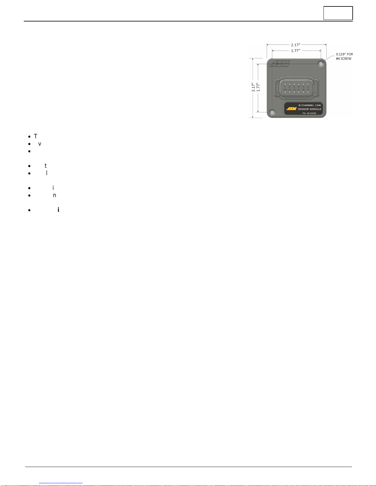
30-2226 6 Channel CAN Sensor Module
Installation
Mechanical
The Sensor Module may be mounted within the vehicle using hook-and-loop
fastener (not included) or bolted (#4 screws included) to a suitable structure; a
mounting/drill diagram is provided below. The module is weather-resistant (IP67)
but is preferably mounted in a cool, dry area such as the driver compartment.
Sensor Wiring
·
The Sensor Module should only be powered through the dedicated power and power ground pins, *not* sensor ground
·
Every connected sensor should be connected to the dedicated sensor ground pins to ensure accurate readings
·
Do not connect the Module's 5V sensor power to anything other than dedicated sensors that require 5V power, e.g.
pressure sensors
·
Route wiring away from sources of noise such as alternators, ignition components, or other high power/frequency wiring
·
Shielded wire is suggested to reduce the susceptibility of noise; the shield should only be grounded/drained on one end
of the wiring harness
·
CAN wiring should utilized twisted pairs (> 1 TPI); shielding is recommended
·
The Sensor Module's sensor ground should be at the same level as the sensor ground of any "tapped" sensors, i.e.
existing/OEM sensors that are connected to an external ECU/device
·
The device pinout section includes a Suggested Interface column. This may make integration with an AEM
Dash easier as sample layoutswill be provided that follow these guidelines.
Quick Setup with AEM Dash
Be sure to install the latest version of the AEM DashDesign software.
Follow this Software Download link directly or follow the graphical instructions below.
The website will always contain the latest release version of DashDesign software. Your version number may be different
than the example above.
Once installed, you will find a library of setup files in your \Documents\AEM\DashDesign directory. In the
\Documents\AEM\DashDesign\Setups\App Specific\AEM 30-2226 6 Ch CAN Sensor Module folder you will find all
currently available setup files for your 30-2226 6 Channel CAN Sensor Module. They have a ".aemcd7" extension. The file
name describes each one.

3
2/5/2019 - DOCUMENT NUMBER: 10-2226 © 2019 AEM Performance Electronics
30-2226 6 Channel CAN Sensor Module
A quick primer on basic setup modifications
The display editor is the core tool for editing a setup. To open the tool, go to Setup | Display...
You can think of the display editor as a collection of tools for creating items on your screens. A DashDesign setup
consists of four logical components: Primary Inputs, Operations, Outputs and Gauges. These are defined as follows:
·
Primary Inputs are raw data manipulated by an operation.
·
Outputs are objects that obtain information from one or more sources or other outputs. An output manipulates the
obtained data according to the operation associated with the output. The result can then be used in a gauge or
another output.
·
Operations are objects that define how the data is manipulated by an output. Examples of operations are scalars,
functions and alarms.
·
Gauges are objects that are placed on a screen page. There are two types of gauge; static and variable.
·
Static gauges do not change their appearance on the screen and include gauges such as text labels or
graphics.
·
Variable gauges change their appearance to reflect data obtained from an output. Examples of variable gauges
are bar graphs, tachos and numerical text gauges.

4
2/5/2019 - DOCUMENT NUMBER: 10-2226 © 2019 AEM Performance Electronics
30-2226 6 Channel CAN Sensor Module
·
Predefined Outputs are pre-configured within the system and can be used in many ways. Some examples include:
Log Mem Free (kb) which displays the amount of free logging memory (logging versions only) and Night Mode Input
Status. This output displays the state of the Night Mode 12vinput (Grey wire in flying lead bundle).
Click the Show Predefined Outputs box in the Display Editor to add all Predefined Outputs
to the list.
Two common modifications necessary are 1.) Creating a new Pressure Sensor Output and 2.) Modifying the tach output
scalar based on the number of engine cylinders.
Creating a new Pressure Sensor Output
Outputs are values, texts or graphics that are used by gauges or other outputs. The output that it passes is determined by
the operation that it uses.
To set up a new output:
·
Click the Insert button in the Outputs tab.
·
Enter the name of the new output. This should describe what the output actually generates.
·
Select the operation to be used by the output from the drop-down list.
·
Select the input from the drop down list.
In our example below, we will create a new scaled pressure sensor output that can be used to drive a gauge on the dash.
It will use the Analog 3 input from the 30-2206 on Pin 7. Three things are required. 1.) You must create a new Output
Name. 2.) You must add an Operation to scale the voltage into pressure units. 3.) You must define a Primary Input.
First create the new Output Name. We will use My Pressure.
For this example, let's assume that the sensor is a typical 0-5V analog sensor that is calibrated as follows: 0.5 volts = 0
psi and 4.5 volts = 100 psi. Consult your sensor documentation for proper calibration values. There are several options
but the easiest method is to use a Function table. Lets create a new Function to define this calibration.
In the Functions tab, create a new Function. We will call it My Pressure Sensor Function; Volts to PSI. It will convert
voltage to PSI.
Click on the (...) symbol to define the function table. Enter the data as shown below to create the calibration curve.
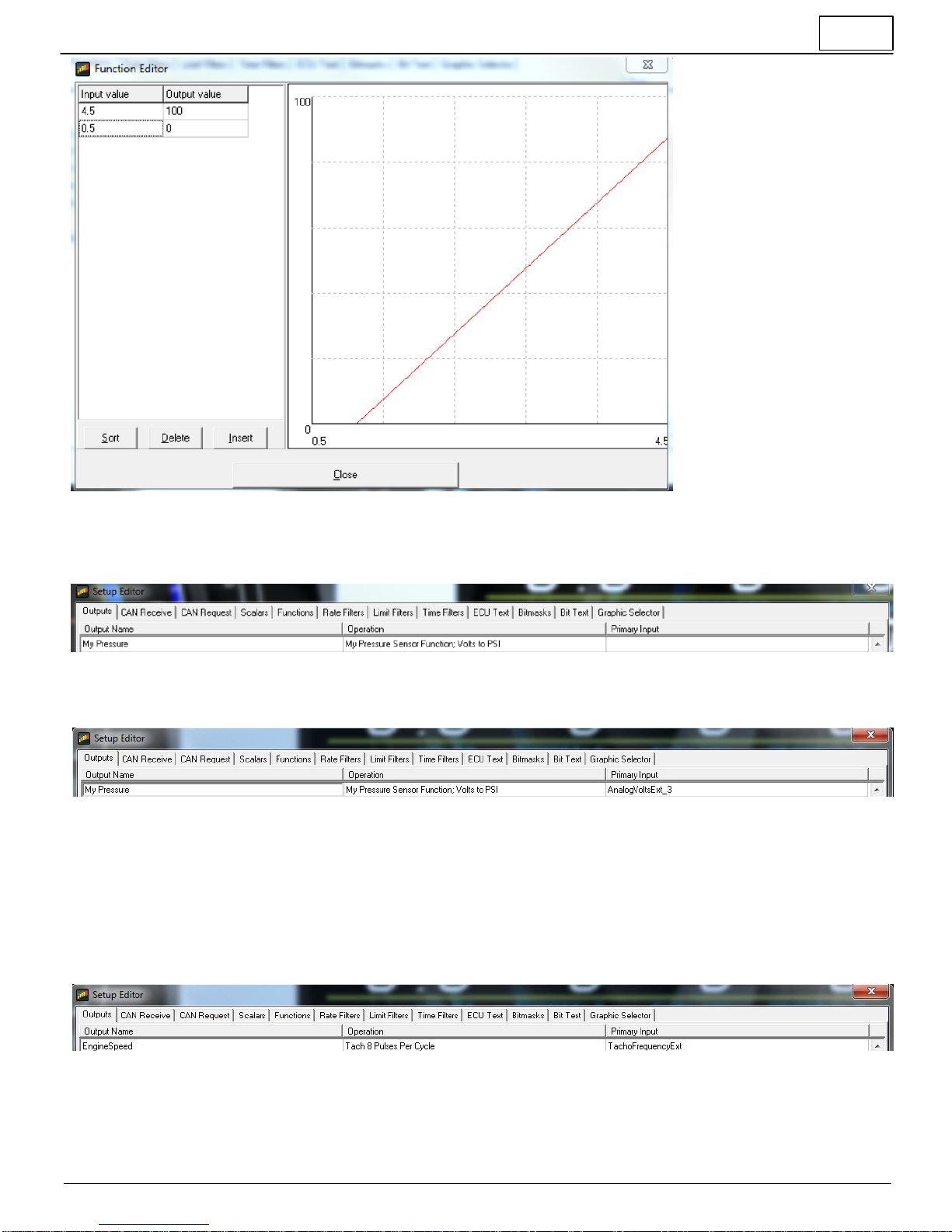
5
2/5/2019 - DOCUMENT NUMBER: 10-2226 © 2019 AEM Performance Electronics
30-2226 6 Channel CAN Sensor Module
Click the Insert button to add data points. Only two points are required for a linear function. The data is interpolated.
More points can be added for non-linear functions.
Next go back to the Outputs tab and choose your new function as the Operation for your new Output.
Finally, select the Primary Input which in this case will be AnalogVoltsExt_3
Your new My Pressure output can pass pressure sensor data, scaled in units of PSI, from the Analog 3 (Pin 7) input of the
30-2226 CAN Sensor Module to any Gauge item in your Dash setup.
Modifying the tach output scalar
AEM provided dash setup files will include pre-configured tach output scalars. It's very simple to configure your tach input.
Find the EngineSpeed output in the Setup Editor. In the example below you can see it uses a scalar for 8 pulses per
engine cycle. This is typical for a V8 engine using a distributor/coil combination when the tach input to the 30-2226 is
tapped into the coil negative terminal.
If your tach input has a different number of pulses per cycle, simply select from the other available options.
Table of contents
Other AEM Accessories manuals

![AEM Lambrecht Meteo u[sonic]WS7 User manual](/data/manuals/12/e/12e6t/sources/aem-lambrecht-meteo-u-sonic-ws7-manual.jpg "AEM Lambrecht Meteo u[sonic]WS7 User manual")


