AEM LAMBRECHT meteo ARCO SDI-12 User manual

Operating Instructions
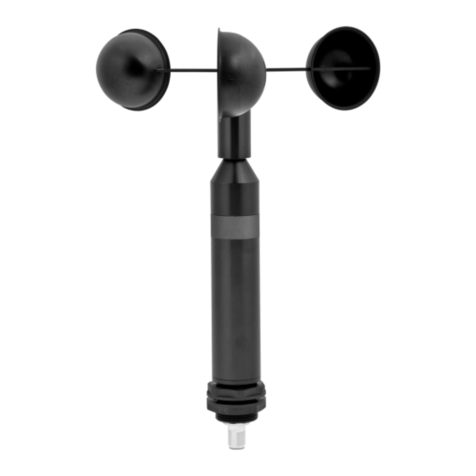
Combined Wind Sensor ARCO SDI-12
(14582) ARCO SDI-12 Operating Instructions
Features and Advantages ARCO SDI-12
▪ Morethan150yearsofexperienceinclassicalmeteorology
▪ Frictionlessdataacquisitionusingnon-contactmeasuring
principle
▪ Highestreliabilityandlongevityduetodoublehigh-perfor-
mancebearingsandspecialalloys
▪ Corrosionresistantsurfacesforlongservicelife
▪ Particularlylowstartingvalue(0.3m/s)
▪ Measuringrangefrom0.3...55m/s
▪ Quickandeasyinstallationthankstopipemountingand
M12plugconnection
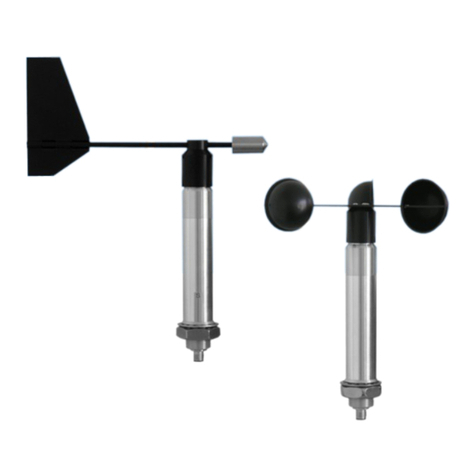
▪ Windvaneand3-armcuprotorexchangeable
▪ Increasedwatertightnessduetowatertrapsintegrated
inthesensor
▪ SDI-12Protocol,Version1.4
▪ Lowcurrentconsumption(<4mAat12VDC)
▪ Thecompactdesignofthesensorreducestheeort
requiredforcomponentsandtheirassemblytimescom-
paredtoindividualdevices.
1

Operating Instructions
Combined Wind Sensor ARCO SDI-12
(14582) ARCO SDI-12 Operating Instructions
Content
1 Introduction 3
2 Start-up·General 3
2.1 Toolsandinstallationmaterial 3
2.2 Unpackingthesensor 3
2.3 Receivinginspection 3
2.4 Powersupply 3
2.5 Mountingthecuprotor 4
2.6 Mountingthewindvane 4
2.7 Installationprocedure(briefdescription) 4
2.7.1 Mountingthesensor 4
2.7.2 Powersupplyandsignalcables 5
2.7.3 Safetyregulations 5
3 Maintenance 5
3.1 Regularmaintenanceandcalibration 5
3.2 Visualinspectionsandcleaning 5
4 Transport 5
5 DimensioneddrawingARCOSDI-12 6
6 ElectricalconnectionARCOSDI-12 7
7 SDI-12Interface 8
8 Technicaldata 14
9 Warranty 14
10 Disposal 14
2

Operating Instructions
Combined Wind Sensor ARCO SDI-12
(14582) ARCO SDI-12 Operating Instructions
2.1 Tools and installation material
Nospecialtoolsarerequiredforthependingassemblyand
maintenancework.Allworkcanbecarriedoutwithstandard
toolssuchasscrewdrivers,open-endspannersandAllen
keys.
2.2 Unpacking the sensor
Thesensorisdeliveredinaseparatepackaging,carefully
protectedagainstmechanicalinuences,inordertoavoid
damageduringtransport.
Thepackagingincludesthefollowingitems:
·1SensorARCOSDI-12
·1OperatingInstructions
Accessories:(dependingonorderscope,packedseparately)
Connectioncablewithcableplug
2.3 Receiving inspection
Pleasecheckthescopeofdeliveryforcompletenessandany
possibletransportdamage.Pleasereportanycomplaintsim-
mediatelyinwriting.
2.4 Power supply
Thecompactsensorrequires12VDCaspowersupplyfor
theelectronics.
1 Introduction
ThesensorsoftheARCOseriesareveryrobust,compact
andextremelyreliable.Duringtheirdevelopment,specialcare
wastakentoensurecompliancewithmeteorologicalrequire-
ments.Thesensorsrepresenttheexperienceofmorethan
150yearsofdevelopmentandproductionofwindsensorsat
Lambrechtmeteo.
Thesystemrecordsthehorizontalairowandprocessesthe
measuredvaluesintothemeteorologicalparameterswind
speedandwinddirection.
Thesensorsandothersystemcomponentsaremountedina
splash-proofanddustproofmetalhousing.
Thehousingandthemeasuringelementsaremadeofcor-
rosion-resistantaluminiumalloys.Sensorhousing,cuprotor
andwindvaneareanodized.
2 Start-up · General
Windcanberepresentedbyavectorsize.Foracomplete
description,windspeedandwinddirectionmustbespecied.
Bothcomponentsaresubjecttospatialandtemporalvaria-
tions,sothatstrictlyspeakingtheyapplyonlytothelocation
wherethemeasuringinstrumentisinstalled.Therefore,
specialattentionshouldbepaidtothechoiceofinstallation
location.
Forwindmeasurementsaccordingtothemeteorologicalstan-
dards(forexampleVDI3786,Part2),themeasuringheight
andmeasuringlocationaredecisivecriteriaforrepresentative
anderror-freemeasurements.Ideally,ameasuringheight
of10mabovethegroundisrecommendedforprofessional
measurements.Furthermore,thereshouldbenoobstacles
suchasbuildings,vehicles,airplanesoranythingsimilar
withinaradiusof150mofthestation.Incasesofmobile
measurementsonvehiclesoronmeasuringcontainers,the
aboveconditionsarenotalwaysachievable.Therefore,ac-
ceptablecompromiseshavetobefoundand,ifnecessary,
documented.
Ingeneral,windmeasuringinstrumentsshouldnotmeasure
thespecicwindconditionsofalimitedarea,butindicatethe
typicalwindconditionsinawiderarea.Thevaluesmeasured
atdifferentplacesmustbecomparable.Therefore,when
mountingthesensor,makesurethattheinstallationsiteis
notlocatedintheslipstreamoflargerobstacles.Thedistance
betweentheobstaclesandthesensorshouldbeatleast10
timestheheightoftheobstacles(correspondstothedenition
ofanundisturbedterrain).Ifthereisnoundisturbedterrain,
thesensormustbepositionedataheightthatisatleast5m
higherthantheobstacleheight.
Ifthesensorisinstalledonaroof,theinstallationlocation
shouldbeinthemiddleoftheroofsothatpreferentialdirec-
tionsareavoided.Ifbothwinddirectionandwindspeedare
measured,thesensorsshould,ifpossible,bemountedat
thesamemeasuringpoint,wherebyanymutualinuenceof
thesensorsshouldbeavoided.Theserequirementscanbe
advantageouslyachievedwiththeARCO-SERIAL,ARCO
SDI-12andARCO-NAVsensors.
The sensor must not be mounted on or near transmit-
ters or antennas. A minimum distance of 2 m must be
kept for interference-free signal transmission.
3

Operating Instructions
Combined Wind Sensor ARCO SDI-12
(14582) ARCO SDI-12 Operating Instructions
2.5 Mounting the cup rotor
Thedrillholesonthecuprotorarearrangedinsuchaway
thatitcanonlybemountedinaspecic,unambiguousposi-
tion.Allscrewshavetobeusedandthecuprotororthewind
vanehavetobexedwiththem.Thisensuresthecorrect
directionofrotation.TherequiredAllenkeyisincludedinthe
scopeofdelivery.
1Halbrundschraube mit Innensechskant
round head screw with hexagon socket
M3x8 DIN7380
2Schalenstern / cup rotor
3Schalensternglocke / cup rotor protective globe
4Skt-Stiftschlüssel / hex head wrench
4
1
2
3
2.6 Mounting the wind vane
Thewindvanecanonlybemountedinaspecicposition.
Useall2screwstoattachthewindvanetothesensorhead.
Thisistheonlywaytoensureacorrectmeasurementofthe
winddirection.
1Schraube mit Innensechskant
screw with hexagon socket
M3x12 DIN7380
2Windfahne / wind vane
3Windfahnenglocke / wind vane protective globe
4Skt-Stiftschlüssel / hex head wrench
4
1
2
3
Please mount the wind vane on the upper part
and the cup rotor on the lower part of the sensor!
2.7 Installation procedure (brief description)
Thesensorisinstalledinthreesteps:
(1)Attachthecableplugtothesensorandpullthecable
throughthemastifnecessary.
(2)Installthesensoronthemast,butbeforetighteningthe
screwsyoumustalignthesensortotheNorth.
(3)Connectthesensorconnectionsforpowersupplyand
signaloutput.
2.7.1 Mounting the sensor
Thesensorismountedonamastpiece(tube)withanoutside
diameterof50mmandaninsidediameterofatleast40mm.
Beforeattachingtheinstrumentwiththetwogrubscrews
M8x12,connectthecable,leaditthroughthepipeandalign
thesensortothenorth.
Forthispurpose,anappropriatemarkingisattachedtothe
instrumenthousing(seedimensioneddrawing).Alignthesen-
sortotheNorthbeforetighteningthescrews.
Pleasemakesurethatthesensorisrmlyattachedtothe
mast!
Alignment of wind vane
Tomeasurethewinddirection,thesensormustbealigned
tothegeographicalNorthdirection.Inordertoalignthewind
sensorperfectlyandrmlytotheNorth,thedevicehasan
integratedmountingaid.Inthelowerpartofthesensorshaft
thereisagrubscrewwithpinwhichcanbeturnedinwards,
pointstotheNorthandiscountersunkintothecorrespond-
ingslotofthemast(ifpresent),sothatthesensorisaligned
correctlyandinanon-rotatingmanner.Ifnecessary,thegrub
screwcanbeturnedinoroutusinganAllenkey(seedimen-
sioneddrawing).
Turnthemarkonthewindvaneexactlyoverthemarkonthe
sensorhousingshaft.Fixthispositionofthewindvane,e.g.
withanadhesivestrip.Afteralignment,removetheadhesive
stripsagain.
Nowyoucantargetthereferencepointviatheaxisofthe
windvane.Thehousingofthesensormustbeturnedonthe
mountingtubesothatthetipofthewindvanepointstothe
Northernreferencepoint.
Forthealignment,apointintheterrainisdenedwhichis
asfarNorthaspossibleinrelationtothenalpositionofthe
winddirectionsensor.
Thepositionofthereferencepointcanrstbeselectedus-
ingatopographicmap(1:25000).Theexactpositionofthe
referencepointisdeterminedwithacompass,whichcanbe
adjustedhorizontallyonatripod.
Pay attention to compass misalignments!
4

Operating Instructions
Combined Wind Sensor ARCO SDI-12
(14582) ARCO SDI-12 Operating Instructions
Whenthetipofthevanepointstothereferencepoint,the
sensorcannallybeattachedwiththetwogrubscrews.
Afunctionaltestinthreedirectionsshiftedeach90°isrecom-
mended.
Observeallrelevantsafetyinstructionswhenmount-
ingasensoronamast.
2.7.2 Power supply and signal cables
Assoonasthesensoriscorrectlymountedandconnectedto
thepre-assembledcable(accessory),thewiresforthepower
supplyandthesignaloutputcanbeconnected.
A4-pinM12cableconnectorisrequiredfortheelectrical
connectionofthesensor.Theshieldingofthecablemustbe
clampedatbothendstotheprotectiveconductor(PE).
Toreducetheriskofinductiveirradiation,thesensor
mustbegroundedcorrectly.
Theexternalconnectionismadebymeansofacentralplug
connector,whichisprotectedinthedevicesocket.Furtherde-
tailsontheelectricalconnectionofthesensorareshowninthe
sections"Dimensioneddrawing"and"Electricalconnection".
Thetypicalpowersupplyofthesensorsis12VDCwitha
currentconsumptionof4mA.Theinputvoltagerangecan
be9...15VDC.
Incaseofpossibleicingoriceformationonthemovingsensor
element,thefunctionislimitedforthedurationoftheicing.
TheoutputsignalofthesensorcorrespondstotheSDI-12
standard.
Thesensorisreadyforuse5secondsafterconnectiontothe
powersupply.
2.7.3 Safety regulations
Since the sensor is often mounted at great heights,
the relevant safety regulations must be followed dur-
ing installation. During the electrical installation work,
the relevant circuits must be disconnected from the
power supply.
The housing must only be opened by authorized
persons!
3 Maintenance
3.1 Regular maintenance and calibration
Thesensorsaredesignedtobeverylow-maintenanceandfor
alongservicelife.Itisrecommendedthatyoucarryoutregu-
larvisualinspectionsforweather-relatedsurfacecontamina-
tionandcleaningifnecessary.Aregularvisualandfunctional
checkofthewindsensorsisrecommended.
If reference measurements are required, it is essen-
tial to ensure that the measured values can only be
compared if the measurements are carried out under
the same conditions. This means that the reference
instrument must be used close to the sensor!
Thesensorisameasuringinstrumentandisthereforesubject
totheuser'sownrecalibrationcycle.
Manufacturerrecommendation:2years.
Wearepleasedtooeryouourqualiedmaintenanceand
calibrationservicestoensurethelong-termfunctionandpreci-
sionoftheoeredcomponents.
3.2 Visual inspections and cleaning
Theuseofthesensorundertherespectiveenvironmental
conditionsrequiresappropriateactions.Itisadvisableto
cleanthehousingandtheshelteratregularintervals.The
intervalsdependontheambientconditionsandthedegree
ofcontamination.Aregularvisualinspectionandfunctional
testisrecommended.
Ifproblemsariseduringthetestswhichyoucannotsolve,
pleasecontactLambrechtmeteoservice:
Tel.: +49-(0)551-4958-0
E-Mail: [email protected]
4 Transport
Intheeventthatthesensoristobeshippedortransportedby
you,itmustbesecurelypackedtoavoidmechanicalimpact
orotherdamage.
5

Operating Instructions
Combined Wind Sensor ARCO SDI-12
(14582) ARCO SDI-12 Operating Instructions
5 Dimensioned drawing ARCO SDI-12
6

Operating Instructions
Combined Wind Sensor ARCO SDI-12
(14582) ARCO SDI-12 Operating Instructions
6 Electrical connection ARCO SDI-12
7

Operating Instructions
Combined Wind Sensor ARCO SDI-12
(14582) ARCO SDI-12 Operating Instructions
7 SDI-12 Interface
ThecommunicationusingSDI-12protocolviaSDI-12interfaceisbasedonthe‘SDI-12ASerial-DigitalInterface
StandardforMicroprocessor-BasedSensors,Version1.4,2017’.TheARCOSDI-12canbeusedinbusmode
paralleltootherARCOSDI-12.
The combined wind sensor behaves like two individual bus participants with their own addresses for wind
speed and wind direction.
ThefollowingsubsetofSDI-12commandswereimplementedintotheARCOSDI-12.
FormoreinformationontheSDI-12protocol,pleaserefertothestandarddocumentationmentionedaboveorthe
websitewww.SDI-12.org.
Implemented SDI-12 commands:
Command Function Answer of the sensor
a! AcknowledgeActive a<CR><LF>
aI! SendIdentication allccccccccmmmmmmvvvxx...xx<CR><LF>
aAb! ChangeAddress b<CR><LF>
aM! StartMeasurement atttn<CR><LF>
aMC! StartMeasurementandRequestCRC atttn<CR><LF>
aC! StartConcurrentMeasurement atttnn<CR><LF>
aCC! StartConcurrentMeasurementand
RequestCRCchecksum
atttnn<CR><LF>
aD0! SendData(Buer0) a<data<CR><LF>
a<data><CRC><CR><LF>
aV! StartVerication atttn<CR><LF>
aX! ResettingtheAddresses a<CR><LF>
a=addressoftherespectivesensor;
Standardsensoraddress:Windspeed=0;Winddirection=1
SDI-12commandsalwaysstartwiththeaddressoftheappropriatesensor.Thereforeallothersensorsonthe
samebuswillignorethesecommands.SDI-12commandsendwith‘!’.Allanswersfromsensorsstartwithits
address,too,butendwiththeASCIIcharacters‘CarriageReturn’<CR>and‘LineFeed’<LF>.
TheSDI-12protocolisbasedontheASCIIcharacterset.ThebaudrateoftheSDI-12protocolis1200Bdand
hasthebyteframeformat:
1 startbit
7 databits(leastsignicantbittransmittedrst)
1 paritybit(evenparity)
1 stopbit.
Acknowledge Active - a!
Thiscommandensuresthatthesensorrespondstorequests.Basicallyitasksthesensortoconrmthatitis
connectedtothebus.
Thesensorreturnsitsaddressand<CR><LF>.
8

Operating Instructions
Combined Wind Sensor ARCO SDI-12
(14582) ARCO SDI-12 Operating Instructions
Syntax
Command Answer
a!a<CR><LF>
a–Sensoraddress a–Sensoraddress
!–Endofcommand <CR><LF>–Endofanswer
Example:
Command Answer
0! 0<CR><LF>
1! 1<CR><LF>
Send Identication - aI!
ThecommandaI!isusedtoaskthesensorforitsmodelnumberandrmwareversion.
Syntax
Command Answer
aI!a14LMGmbH1514582x1.1<CR><LF>
a–Sensoraddress a–Sensoraddress
I–Command"SendIdentication"
a14LMGmbH1514582x1.1
14–2charactersSDI-12version-No.
14=version1.4
LMGmbH15–8charactersmanufacturer’s
(=LambrechtmeteoGmbH)
14582x–6characterssensortype
14582S–Windspeed
14582D–Winddirection
1.1–Firmwareversion
!–Endofcommand <CR><LF>–Endofanswer
Example:
Command Answer
0I! 014LMGmbH1514582S1.1<CR><LF>
1I! 114LMGmbH1514582D1.1<CR><LF>
Change address - aAb!
Thefactorysettingfortheaddressofthewindspeedis"0",forthewinddirection"1".
Ifthereareseveralsensorsconnectedtoonebus,thesensoraddresscanbechangedwiththecommandaAb!.
The address is always a singleASCII character. Standard for addresses are theASCII characters "0" to "9"
(decimal48 to57). Ifthere aremore than10 sensorsconnected toone bus,using thecharacters "A"to "Z"
(decimal65to90)and"a"to"z"(decimal97to122)isallowed.Thesensoranswerswithitsnewaddressand
<CR><LF>.
Aftertheaddressischanged,oneshouldnotsendfurthercommandstothesensorforaperiodofonesecond
(seealso"SDI-12Standard,Version1.4,2017").
9

Operating Instructions
Combined Wind Sensor ARCO SDI-12
(14582) ARCO SDI-12 Operating Instructions
Syntax
Command Answer
aAb! b<CR><LF>
a–Oldsensoraddress b–Newsensoraddress
A–Command‘ChangeAddress’
b–Newsensoraddress
!–Endofcommand <CR><LF>–Endofanswer
Example:
Command Answer
0A1! 1<CR><LF>
Start Measurement - aM!
The"aM!"commandrequeststhesensortoprocesstheavailablemeasurementdataandwritethemtoanoutput
string.UnlikethestandardsensorsdescribedintheSDI-12documentation,theARCOSDI-12measurescontinu-
ously.ThisiswhytheARCOSDI-12alwaysrespondswith"a000".Thedataisthereforeimmediatelyavailable.
ThisisalsothereasonwhytheARCOSDI-12doesnotsenda"servicerequest"andignoresmeasurementinter-
ruptioncommands.Thedatacanberetrievedwiththecommand"aD0!"(seebelowunder"Senddata").Thedata
isnotoverwrittenuntilthenext"C"or"M"commandandcanberetrievedseveraltimes.
Syntax
Befehl Antwort
aM!a0004<CR><LF>
a–Sensoraddress a–Sensoraddress
M–Command"StartMeasurement" 000– Secondsthesensorneedsuntilthe
measureddatacanbereturned
(=0s–Dataimmediatelyavailable)
04–Numberofprovidedmeasureddata
!–Endofcommand <CR><LF>–Endofanswer
Example:
Command Answer
1M! 10004<CR><LF>mos
ThemeasureddatacanberequestedwiththecommandsaD0!andaD1!(seeSend Data).
10

Operating Instructions
Combined Wind Sensor ARCO SDI-12
(14582) ARCO SDI-12 Operating Instructions
Start Measurement and Request CRC - aMC!
Samecommand as "aM!"but inadditionto thegenerated data thesensor returnsa3-digit CRCchecksum.
ForinformationonhowtheCRCchecksumisgenerated,pleaseconsult‘SDI-12Standard,Version1.4,2017,
chapter4.4.12’.
Syntax
Command Answer
aMC! a0004<CR><LF>
a–Sensoraddress a–Sensoraddress
M–Command‘StartMeasurement 000–Secondsthesensorneedsuntilthe
andRequestCRC’ measureddatacanbereturnedwith"CRC"
(=0s–Dataimmediatelyavailable)
C–Requestfortransmissionofthe 4–Numberofprovidedmeasureddata
CRCchecksum <CR><LF>–endofanswer
!–Endofcommand
Example:
Command Answer
1MC! 10004<CR><LF>
Start Concurrent Measurement - aC!
The"ConcurrentMeasurement"enablesthedataloggertomeasuresimultaneouslywithmultiplesensorsonthe
samebus.
The"aC!"commandrequeststhesensortoprocesstheavailablemeasurementdataandwritethemtoanoutput
string.UnlikethestandardsensorsdescribedintheSDI-12documentation,theARCOSDI-12measurescontinu-
ously.ThisiswhytheARCOSDI-12alwaysrespondswith"a000".Thedataisthereforeimmediatelyavailable.
ThisisalsothereasonwhytheARCOSDI-12doesnotsenda"servicerequest"andignoresmeasurementinter-
ruptioncommands.Thedatacanberetrievedwiththecommand"aD0!"(seebelowunder"Senddata").Thedata
isnotoverwrittenuntilthenext"C"or"M"commandandcanberetrievedseveraltimes.
Syntax
Command Answer
aC! a00004<CR><LF>
a–Sensoraddress a–Sensoraddress
C–Command‘StartConcurrent 000– Secondsthesensorneedsuntilthe
Measurement’ measureddatacanbereturned
(=0s–Dataimmediatelyavailable)
4–Numberofprovidedmeasureddata
!–Endofcommand <CR><LF>–endofanswer
Example:
Command Answer
1C! 100004<CR><LF>
ThemeasureddatacanberequestedwiththecommandaD0!(see"SendData").
11

Operating Instructions
Combined Wind Sensor ARCO SDI-12
(14582) ARCO SDI-12 Operating Instructions
Start Concurrent Measurement and Request - CRC aCC!
Samecommandas"aC!"butinadditiontothegenerateddatathesensorreturnsa3-digitchecksum.Forinformation
onhowtheCRCchecksumgetsgenerated,pleaseconsult‘SDI-12StandardVersion1.4,2017,chapter4.4.12’.
Syntax
Command Answer
aCC! a00004<CR><LF>
a–Sensoraddress a–Sensoraddress
C–Command‘StartConcurrent 000–Secondsthesensorneedsuntilthe
Measurement’ measureddatacanbereturnedwith"CRC"
(=0s–Dataimmediatelyavailable)
C–Requestfortransmissionofthe 04–Numberofprovidedmeasureddata
CRCchecksum <CR><LF>–Endofanswer
!–Endofcommand
Example:
Command Answer
1CC! 100004<CR><LF>
Send Data - aD0!
Thedatarequestedbythesensorwiththecommands"C"or"M"canberetrievedwiththecommand"aD0!".The
sensorusesthecorrespondingsigns("+"or"-")aseldseparators.Ifthedatawasrequestedwitha"CC"or"MC"
command,aCRCchecksumisalsoreturned.FormoreinformationonhowtogeneratethisCRCchecksum,see
"SDI-12Standard,Version1.4,2017,chapter4.4.12".
Afterthemeasurement,thedataisstoredinthebuer"D0"andretrievedwiththecommand"aD0!".
Wind speed (address = 0)
Measured data Unit
Buer0
Momentaryvaluesincelastmeasurement m/s
Minimumvaluesincelastmeasurement m/s
Maximumvaluesincelastmeasurement m/s
Averagevaluesincelastmeasurement m/s
Wind direction (address = 1)
Measured data Unit
Buer0
Momentaryvaluesincelastmeasurement °
Minimumvaluesincelastmeasurement °
Maximumvaluesincelastmeasurement °
Averagevaluesincelastmeasurement °
12

Operating Instructions
Combined Wind Sensor ARCO SDI-12
(14582) ARCO SDI-12 Operating Instructions
Syntax for measurements with command "aC!" or "aM!"
Command Answer
aD0! a<values><CR><LF>
a–Sensoraddress a–Sensoraddress
D–Command‘SendData’ <values>–Requesteddataseparatedby
0–Requestforthedatainbuer0 resp.sign("+"or"-")
or
1=buer1
!–Endofcommand <CR><LF>–Endofanswer
Example:
Command Answer
0C! 000004<CR><LF>
0D0! 0+0.1+0.1+0.1+0.1<CR><LF>
Syntax for measurements with command "aCC!" or "aMC!"
Command Answer
aD0! a<values><CRC><CR><LF>
a–Sensoraddress a–Sensoraddress
D–Command‘SendData’ <values>–Requesteddataseparatedby
0–Requestforthedatainbuer0 respsign("+"or"-")
or
1=buer1 <CRC>–3-digitCRCchecksum
!–Endofcommand <CR><LF>–Endofanswer
Reset addresses - aX!
Ifinadvertentlythesameaddresshasbeenassignedtowinddirectionandwindspeed,thesensorcanbereset
toaddress0forwindspeedandaddress1forwinddirectionwiththecommand"aX!".
13

Operating Instructions
Combined Wind Sensor ARCO SDI-12
(14582) ARCO SDI-12 Operating Instructions
Subjecttochangewithoutnotice.
8 Technical data
ARCO SDI-12Id-No. 00.14582.070470
Range Temperatures-40...+70°C
ofapplication: Windspeed0...55m/s
0...100%r.h.
Protocol: SDI-12
Supplyvoltage: Sensor9...15VDC·4mAat12VDC
Housing: Seawaterresistantaluminium
speciallycoated
IP65inverticalpositionofuse
Dimensions: Seedimensioneddrawing
Weight: Approx.1.7kg
Parameter wind direction
Measuringrange: 0...360°
Accuracy: ±1%
Resolution: <1°
Startingvalue: 0.3m/s
Dampingratio: 0.5...0.6
Parameter wind speed
Measuringrange: 0.3...55m/s
Accuracy: ±2%FSat0.3...55m/s
Resolution: <0.1m/s
Startingvalue: 0.3m/s
Distanceconstant: 4m
Accessories:(pleaseorderseparately)
SensorconnectioncablewithplugconnectorM12,4-pin
Length: 12m
Id-No: 32.14567.060000
SensorconnectioncablewithplugconnectorM12,4-pin
Length: 15m
Id-No: 32.14567.060010
(Otherlengthsavailableonrequest.)
Options:
(9340) Visualisationandevaluationsoftware
MeteoWare-CS-3Basic
Id-No.36.09340.000000
Standards
• EMC/EMI:EN60945
• Lowvoltageguideline73/23/EWGandVDE0100
• WMONo.8
• VDI3786part2
• SDI12,1.4,2017
9 Warranty
Please note the loss that unauthorised manipulation
of the system shall result in the loss of warranty and
non-liability. Changes to system components require
express written permission from LAMBRECHT meteo
GmbH. These activities must be performed by a qualied
technician.
The warranty does not cover:
1. Mechanicaldamagecausedbyexternalimpacts(e.g.
icefall,rockfall,vandalism).
2. Impactsordamagecausedbyover-voltageor
electromagneticeldswhicharebeyondthestandards
andspecicationsofthedevice.
3. Damagecausedbyimproperhandling,e.g.byusing
thewrongtools,incorrectinstallation,incorrectelectrical
installation(incorrectpolarity)etc.
4. Damagecausedbyusingthedeviceoutsidethespecied
operationconditions.
10 Disposal
LAMBRECHTmeteoGmbHislistedandregisteredatthe
StiftungElektro-AltgeräteRegisterearunder:
WEEE-Reg.-No. DE 45445814
Inthecategoryofmonitoringandcontrolinstruments,device
type:"Monitoringandcontrolinstrumentsforexclusivelycom-
mercialuse".
Within the EU
Thedevicehastobedisposedaccording
totheEuropeanDirectives2002/96/ECand
2003/108/EC(WasteElectricalandElec-
tronicEquipment).Donotdisposetheold
deviceinthehouseholdwaste!Foran
environmentallyfriendlyrecyclinganddis-
posalofyourolddevice,contactacertied
disposalcompanyforelectronicwaste.
Outside the EU
Pleasefollowtheregulationsinyourcountryregardingthe
appropriatedisposalofwasteelectronicequipment.
14
LAMBRECHT meteo GmbH Tel +49-(0)551-4958-0
Friedländer Weg 65-67 Fax +49-(0)551-4958-312
Germany Internet www.lambrecht.net
14582_ARCO_SDI-12_b-de.indd21.22
Table of contents
Other AEM Accessories manuals
![AEM Lambrecht Meteo u[sonic]WS7 User manual AEM Lambrecht Meteo u[sonic]WS7 User manual](/data/manuals/12/e/12e6t/sources/aem-lambrecht-meteo-u-sonic-ws7-manual.jpg)


