AEM Lambrecht METEOROLOGY User manual

USER MANUAL
Wind Sensors
METEOROLOGY

aem.eco
LAMBRECHT meteo |AEM | METEOROLOGY
page –2
Warranty
Please note the loss of warranty and non-liability by unauthorized manipulation of the system. You need a written
permission of the LAMBRECHT meteo GmbH for changes of system components. These activities must be
operated by a qualied technician.
The warranty does not cover:
1. Mechanical damages caused by external impacts (e. g. icefall, rockfall, vandalism).
2.
3. Damages caused by improper handling, e. g. by wrong tools, incorrect installation, incorrect electrical
installation (false polarity) etc.
4.
Content
Warranty 2
Versions 3
Measuring elements 3
Installation wind vane 3
Putting into operation 3
Maintenance 7
Troubleshooting 7
Dimensional drawing 14566 8
Dimensional drawing 14576 9
Connection diagram 14566 and 14576 10
Cable assignment 11
Disposal 11
Technical data 12

aem.eco
LAMBRECHT meteo |AEM | METEOROLOGY
page –3
Versions
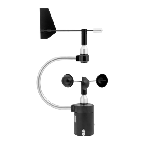
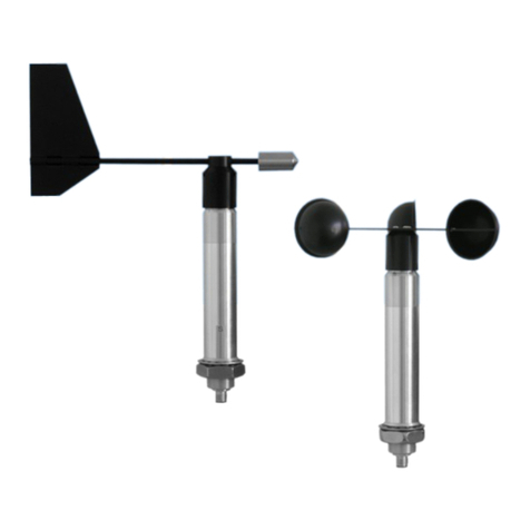
The family of METEOROLOGY sensors includes the heatable sensors for wind speed type 14576 and wind direction
type 14566.
Measuring elements
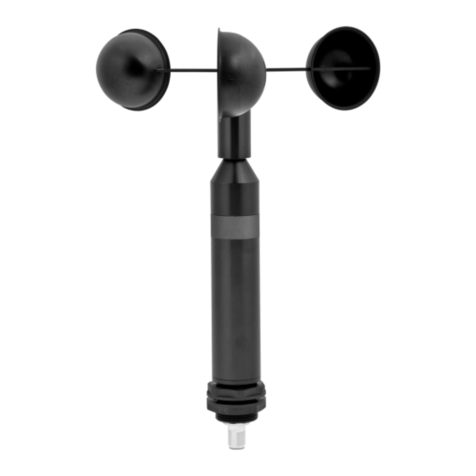
CUP ROTOR
The three-armed cup rotor is set into rotation by the wind. The number of rotations is a measure of the wind
speed. The design features of the cup rotor, which are permanently monitored by quality management during the
manufacturing process, ensure optimum linearity.
WIND VANE
to the wind direction. The size and shape of the wind vane is optimized for a low starting value, while achieving an
excellent compromise in terms of dynamic properties (inertia, natural frequency).
Installation wind vane
1.
screws.
2. Now the cable with the mounted coupling socket is pulled through the mounting mast with a diameter of approx.
50 mm.
3. The plug-in connection is made and secured by screwing.
4. Then the sensor is placed on the mast.
5. To align the sensor to the north, the two points on the sensor housing and the dome are positioned one above the
6. This allows a point determined in the south to be targeted via the sword of the wind vane and the fastening screw
to be tightened in this position using the enclosed Allen key (4 mm).
Putting into operation
The wind can be represented by a vector quantity. For a complete description of the wind it is necessary to specify its
speed and direction. The two components are subject to spatial and temporal variations; thus, strictly speaking, they
are valid only for the site where the measuring instrument is put up. We therefore recommend to select the place of
installation very carefully.

aem.eco
LAMBRECHT meteo |AEM | METEOROLOGY
page –4
SELECTING THE PLACE OF INSTALLATION
Thus, when installing the sensor you should make sure the place of installation is not under the lee of great obstacles.
The distance between the obstacles and the sensor should be 10 times the height of the obstacles (this corresponds
If an undisturbed terrain of this kind does not exist the sensor must be put up at a height of at least 5 m above the
obstacle height. If the sensor must be installed on a roof top the place of installation must be in the middle of the roof
to avoid predominant wind directions.
If you want to measure both wind direction and wind speed, install the sensors at the same measuring point,
requirement since the sensors are set up side by side. Their horizontal distance should be approximately 1.5 m. The
two sensors must be staggered vertically so that the lower edge of the upper wind speed sensor is 0.1 to 0.5 m above
the upper edge of the lower wind direction sensor.
MOUNTING THE SENSOR ON THE MAST
Mount the sensor at the top of a grounded tube with an outer diameter of 50 to 52 mm. Make sure the device is easily
accessible so that you can set up the north direction for the wind direction sensor and perform any maintenance
work. To reach the sensors use a ladder of the appropriate length or a telescoping working platform of the
appropriate height.
Ladders or other lifting helps must be absolutely in order and must be guarantee a secure support!
You can also use masts that can turn around their vertical axis or masts consisting of individual segments or
telescoping masts that you can secure after setting up the north direction.
If wind speed and wind direction are measured at the same time, the measurement generally takes place not only at
the top of a mast but also at the ends of a cross arm. The arms must stay torsion-free and vibration-proof even at high
wind speeds and they must be accessible for you to perform mounting and maintenance work.
When you install the connecting cables make sure not to excessively shorten the cable leading to the connector in
the lower part of the sensor casing so that you can later maintain or dismount the sensor.

aem.eco
LAMBRECHT meteo |AEM | METEOROLOGY
page –5
VIEW OF CABLE ROUTING ON A WIND TRAVERSE
ESTABLISH ELECTRICAL CONNECTION
All sensors of the METEOROLOGY series are electrically connected via a 12-pin connector (pin) embedded in the
base of the housing.
Because the installation takes place in a dangerous height, the assembly personal must follow the rules
for prevention of accidents.
CABLE ROUTING
The connecting cable is suitably led along the mast between the data evaluation device (indicating instrument
or data acquisition system) and the sensor. The cable must be fastened using appropriate cable ties (their length
depends on the mast diameter). You can also install the entire connecting cable within the tube elements of the mast
if the mast is prepared correspondingly.
Lead the cable in a wide curve from the mast to the bottom of the casing so that you can later easily
dismount the cable.
Example illustration:
Cable routing through an
EMC compliant Pg socket
Please make sure the cable is protected from humidity on the side of the data processing system. Generally, Pg
sockets that use a rubber joint to prevent humidity from penetrating into the terminal box of the data processing

aem.eco
LAMBRECHT meteo |AEM | METEOROLOGY
page –6
OUTPUT SIGNAL
When you connect the output signal please note the assignment of the wires of the open cable end shown in
the internal circuit diagrams on the following pages. The individual output wires lead you to the corresponding
connecting terminals of the data acquisition section.
ELECTRONICS SUPPLY
On models 14566 and 14576, the electronics are supplied via the J(-) and H(+) wires of the 12-pin connector.
The permissible values are:
Model Voltage Current
The electronic heating of versions 14566 and 14576 is supplied via an external power supply unit. The necessary
voltage of 24 VDC is connected via the M(-) and G(+) wires.
GROUNDING
To reduce the risk of inductive interference the sensor must be properly grounded (screening on both sides). The use
of ready-made connecting cables from LAMBRECHT meteo guarantees a proper grounding between sensor and
cable. You just have to connect the cable screening to the ground of the indicator or the data acquisition unit. When
other cables are used, you must create an appropriate screening.
ADJUSTING THE WIND VANE
For wind direction measurements the north mark on the sensor must be aligned with the geographical north
direction; the allowed maximum alignment deviation is ±3 degrees. To set up the sensor’s north orientation select
reference point can be selected using a topographical map (1:25000). The exact position of the reference point is
determined using an amplitude compass that can be adjusted horizontally on a stand.
A point on the rotary knob and another point on the casing shaft represent the north mark of the wind direction
point by aiming at it over the axis. Now you must turn the sensor casing on the mounting tube until the tip of the wind
vane points to the reference point in the north.
Please make sure there is no magnetic deviation of the compass.
When the north direction is set up for the wind direction sensor, tighten the headless screws in the lower part of the
casing and remove any adhesive tape, if necessary. Using an indicating instrument or a data acquisition system,
90 degrees from each other.
If the local conditions do not allow the reference point to be set up in a northerly direction, the procedure can be
applied analogously to a southerly reference point. In this context, it must be ensured that the north mark on the wind
sensor does not point to the reference point, but in the opposite direction.

aem.eco
LAMBRECHT meteo |AEM | METEOROLOGY
page –7
Maximum interval Wind direction and wind speed
a) 1 week Time mark of the measuring system (correction if necessary)
Visual inspection of the device function
Rough check of the measured values
b) 6 months Check of the measured value transmission
c) 2 years Calibration of the wind sensors
Check of the north alignment
Maintenance
The sensor design permits long periods of maintenance-free operation. To obtain useful measured data the
measuring station must be systematically controlled and monitored. The properties of the sensor may change due to
We therefore recommend to check the measuring station periodically according to intervals listed in this table:
If any problems should arise during the checks that you are unable to solve, please contact the LAMBRECHT meteo
service at:
Tel: +49-(0)551-4958-0
E-Mail support@lambrecht.net
Troubleshooting
If the sensor delivers no signal, the points below should be checked:
1.
connection of the power supply as well as the signal line.
2. Is the wind vane or the cup rotor damaged? You can order the spare parts from LAMBRECHT meteo and replace
them yourself by loosening the screws.
ID 32.14565.001010
Wind vane for wind direction sensor
ID 33.14565.017000 (order separately)
2 x Countersunk screw (loss-proof) for wind vane
ID 32.14576.005010
Cup rotor for wind speed sensor
ID 35.73801.618501 (order separately)
3 x Semi-circular screw for cup rotor
When mounting the cup rotor, use all three screws to ensure the correct and secure t of the cup rotor.
If there is no output signal despite a positive check of the a. m. points 1 and 2, the sensor must be sent to the
manufacturer for repair.

aem.eco
LAMBRECHT meteo |AEM | METEOROLOGY
page –8
Dimensional drawing 14566
WeitergabesowieVervielfältigungdieserUnterlage,VerwertungundMitteilungihresInhaltsnicht
gestattet,sowienichtausdücklichzugestanden.ZuwiderhandlungverpflichtenzuSchadensersatz.
AlleRechtefürdenFallderPatenterteilungoderGebrauchsmuster-Eintragungvorbehalten.
Passingonandduplicationofthisdocument,utilizationandcommunicationof
it's contentsprohibitedunlessdefinitelypermitted.Infringementisboundto
compensation.Allrightsreservedforpatentorregisteredpattern.
Maße ohne Toleranzangabe nach
Zust. Änderungen Datum Name Dateiname Ersatz für:
Blatt
Bl
MaßstabMaterial
Bearb.
Gepr.
Datum Name
Artikelnummer
DIN ISO 2768-m
Benennung
80.14566.000B01.idw
1 / 1
15.12.2022 curdt
80.14566.000B01
Oberfläche
Maßzeichnung 00.14566.400000
1
A4
1:2,5
Norm.
Revision
364
8
M
10
20
237
225ca.
123
74
n
Für 50 mm Masten geeignet
suitable for 50 mm poles

aem.eco
LAMBRECHT meteo |AEM | METEOROLOGY
page –9
Dimensional drawing 14576
WeitergabesowieVervielfältigungdieserUnterlage,VerwertungundMitteilungihresInhaltsnicht
gestattet,sowienichtausdücklichzugestanden.ZuwiderhandlungverpflichtenzuSchadensersatz.
AlleRechtefürdenFallderPatenterteilungoderGebrauchsmuster-Eintragungvorbehalten.
Passingonandduplicationofthisdocument,utilizationandcommunicationof
it's contentsprohibitedunlessdefinitelypermitted.Infringementisboundto
compensation.Allrightsreservedforpatentorregisteredpattern.
Maße ohne Toleranzangabe nach
Zust. Änderungen Datum Name Dateiname Ersatz für:
Blatt
Bl
MaßstabMaterial
Bearb.
Gepr.
Datum Name
Artikelnummer
DIN ISO 2768-m
Benennung
80.14576.000B01.idw
1 / 1
14.12.2022 curdt
80.14576.000B01
Oberfläche
Masßzeichnung 00.14576.400000
1
A4
1:2
Norm.
Revision
8
M
10
172
20
74
n
Für 50 mm Masten geeignet
suitable for 50 mm poles
n
220,3
n
55

aem.eco
LAMBRECHT meteo |AEM | METEOROLOGY
page –10
Connection diagram 14566 and 14576
WeitergabesowieVervielfältigungdieserUnterlage,VerwertungundMitteilungihresInhaltsnicht
gestattet,sowienichtausdücklichzugestanden.ZuwiderhandlungverpflichtenzuSchadensersatz.
AlleRechtefürdenFallderPatenterteilungoderGebrauchsmuster-Eintragungvorbehalten.
Passingonandduplicationofthisdocument,utilizationandcommunicationof
it's contentsprohibitedunlessdefinitelypermitted.Infringementisboundto
compensation.Allrightsreservedforpatentorregisteredpattern.
Zust. Änderungen Datum Name Dateiname Ersatz für:
Blatt
Bl
Bearb.
Gepr.
Datum Name
Artikelnummer
Benennung
80.14566.000E03.idw
1 / 1
16.12.2022 curdt
80.14566.000E03
Anschlussplan 00.14566.400000 /
00.14576.435000
1
A4
Norm.
Revision
EFG
DMH
J
L
C
BAK
Anschlussbild / connection diagram
Buchstabe
letter PIN Kabelfarbe
color code
Funktion
function
F 1 RD / BU + 0...20 mA
E 2 GY / VT GND (I OUT)
D 3 WH + 4...20 mA
C 4 GY RS485 (A+)
L 5 VT Fout 700 Hz
(WG)
B 6 BU GND (A GND)
A 7 GN SDI-12 OUT
K 8 YE RS485 (B-)
J 9 OG + 10...30 VDC
(Elektronik)
H 10 RD GND
M 11 BN - 24 VDC
Heating
G 12 BK + 24 VDC
Heating
0...20 mA = 0...50 m/s
4...20 mA = 0...50 m/s 0...20 mA = 0...360°
4...20 mA = 0...360°

aem.eco
LAMBRECHT meteo |AEM | METEOROLOGY
page –11
Coupling socket
ID 65.53070.470100
View of the connector from
the plug contact side
Cable assignment
ID 32.14565.060 xxx
Disposal
LAMBRECHT meteo GmbH is listed and registered at the Stiftung Elektro-Altgeräte Register ear under:
WEEE-Reg.-Nr. DE 45445814
In the category of monitoring and control instruments, device type: “Monitoring and control instruments for
exclusively commercial use”.
Within the EU
The device has to be disposed according to the European Directives 2002/96/EC and 2003/108/EC
(Waste Electrical and Electronic Equipment). Do not dispose the old device in the household waste!
company for electronic waste.
Outside the EU
Please follow the regulations in your country regarding the appropriate disposal of waste electronic equipment.

aem.eco
LAMBRECHT meteo |AEM | METEOROLOGY
METEOROLOGY_b-de.indd 01.23
Photo copyright: © Alexanderthegreat - Adobe stock
Copyright © 2022 LAMBRECHT meteo GmbH. All rights reserved.
Information in this document subject to change without notice.
LAMBRECHT meteo GmbH Tel +49-(0)551-4958-0
Friedländer Weg 65-67 Fax +49-(0)551-4958-312
37085 Göttingen E-Mail info@lambrecht.net
Germany Internet www.lambrecht.net
page –12
Technical data
METEOROLOGY Wind direction sensor METEOROLOGY Wind speed sensor
ID 00.14566.400000 00.14576.400000
Measuring range 0...360° 0.3...50 m/s
Accuracy 1° 2 % FS
Resolution 1° 0.1 m/s
Starting value 0.3 m/s 0.3 m/s
Output 0...20 mA (maximum load 500 Ohm)
4...20 mA (maximum load 500 Ohm)
0...20 mA = 0...50 m/s
(maximum load 500 Ohm)
4...20 mA = 0...50 m/s
(maximum load 500 Ohm)
Operating ranges temperature: -30...+70 °C heated;
0...+70 °C unheated;
survival wind speed: 100 m/s
temperature: -30...+70 °C heated;
0...+70 °C unheated
survival wind speed: 100 m/s
Supply voltage 10...30 VDC 10...30 VDC
Heating voltage 24 VDC, 600 mA (for controlled heating) 24 VDC, 600 mA (for controlled
heating)
Housing seawater resistant aluminum; anodized;
IP 53
seawater resistant aluminum;
anodized; IP 53
Measuring elements wind vane, aluminum, dimensionally
stable
three-arm cup rotor, aluminum,
breakproof
Dimensions see dimensional drawing;
for mounting on tube Ø 49...51 mm
see dimensional drawing;
for mounting on tube Ø 49...51 mm
Weight 0.6 kg 0.4 kg
Included in delivery plug, 12-pin; if a cable is ordered as well,
the plug is mounted on it
plug, 12-pin; if a cable is ordered as
well, the plug is mounted on it
ACCESSORIES (please order separately)
ID 32.14565.060000
ID 32.14565.060020
SPARE PARTS (please order separately)
ID 32.14565.001010 Wind vane for wind direction sensor (Screws see “Troubleshooting“)
ID 32.14576.005010 Cup rotor for wind speed sensor (Screws see “Troubleshooting“)
In case of possible icing and ice formation on the movable sensor measuring element, the function is
reduced for the time of icing.
Table of contents
Other AEM Accessories manuals

![AEM Lambrecht Meteo u[sonic]WS7 User manual AEM Lambrecht Meteo u[sonic]WS7 User manual](/data/manuals/12/e/12e6t/sources/aem-lambrecht-meteo-u-sonic-ws7-manual.jpg)
