DIP SWITCH SETTINGS
Recommended time delay settings:
Offices and conference rooms: . . . . . . . . . . . . . . .10-16 min.
Open office spaces: . . . . . . . . . . . . . . . . . . . . . . .10-16 min.
Classrooms: .............................10-16min.
Warehouses: ..............................8-10min.
Hallways: ................................10-16min.
Note: Frequent cycling of lights can reduce
lamp life; use caution when setting the time
delay below 8-10 min.
TROUBLESHOOTING
WARNING – Turn off power at the circuit breaker before working with
high voltage.
The lights do not turn on with occupancy:
LED does NOT flash:
1. Check the sensitivity settings. Increase (clockwise) as needed.
2. Check all sensor and power pack wire connections.
3. Check for 24VDC at sensor (red & black).
• If 24VDC is present, replace the sensor.
• If 24VDC is not present, check that high voltage (120 or 277VAC) is
present to power pack. If it is, replace power pack.
4. Call (800) 223-4185 for technical support.
LED does flash:
1. Check all sensor and power pack wire connections.
2. Check for 24VDC at the power pack’s blue wire connection to sensor while
someone moves in front of sensor to activate the LED. If there is no
voltage, replace the sensor. If there is voltage, replace the power pack.
3. Call (800) 223-4185 for technical support.
The lights do not turn o automatically:
1. Check the sensitivity settings. Decrease (counterclockwise) as needed.
2. Check all sensor and power pack wire connections.
3. Disconnect power pack’s blue wire:
If the lights do not turn off, replace power pack.
If the lights turn off, the problem may be in the sensor, to check:
• Turn sensitivity and time delay to minimum and allow the sensor to time
out. If the lights turn off, the sensor is working properly. The lights may
be staying on because the sensor is detecting motion or some type of
interference. Go through the sensor adjustment process again.
4. If sensor still does not operate properly, call (800) 223-4185 for
technical support.
Override Function:
In the event of unit failure or if it is necessary to leave the lights on, set DIP
switch #5 to ON. This will bypass the automatic function of the sensor to
allow manual on/off control of circuits.
SELECTING SENSOR LOCATION
Proper placement of the sensor is critical in achieving maximum performance
of the device. Passive infrared sensors respond to movement of heat
sources, such as humans, through their direct viewing area. Use the following
rules when selecting the location of the sensors:
• Do not place sensors where viewing area contains direct air currents, or
concentrated, direct reflected light.
• Sensor viewing is line-of-sight, therefore, do not place sensors where
desired coverage is obstructed by walls, columns or other objects.
• Do not place sensors directly above baseboard heaters or forced air
outlets.
• Use sensors only with lighting loads.
• Sensors should be used in dry, indoor locations.
INSTALLATION
The WA1001 and HS1001 can be mounted to a wall or ceiling. Brackets
are available that give flexibility for positioning the sensor.
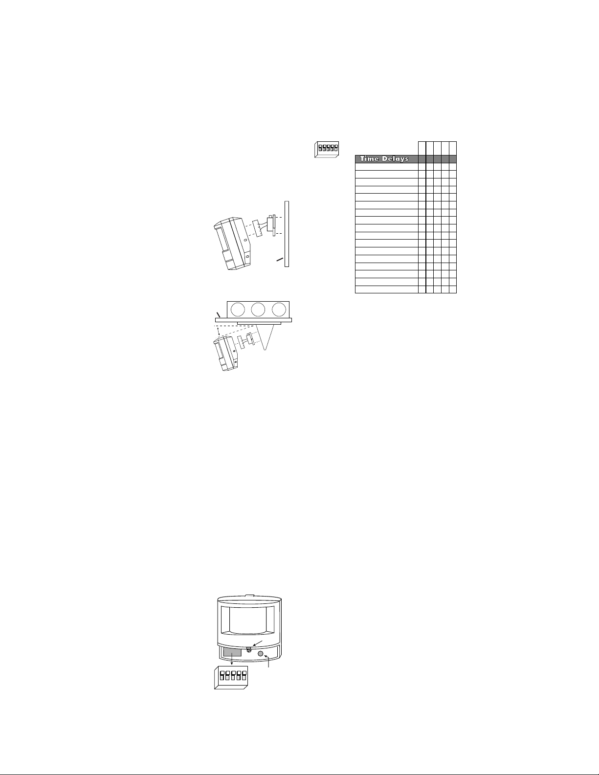
Swivel Mount Bracket
The swivel mounting bracket gives the angle
adjustment flexibility needed in some
applications, especially for low or very high
mounting heights, or when mounting to a wall.
This is achieved by aligning the angle markings
on the sensor mount with the alignment mark on
the wall mount. The swivel mounting bracket can
be used with or without the ceiling mount bracket.
Ceiling Mount Bracket
The ceiling and swivel mounting brackets can be
used together when mounting the WA1001 or
HS1001 to the ceiling. This arrangement gives
angle adjustment flexibility.
Align the angle marks on the
swivel mount bracket to the angle desired. Note
that the ceiling mount bracket adds 18 to the
angle set with the swivel mount bracket.
The ceiling mount bracket is designed to
connect to a standard 3-0 Mud/Plaster Ring.
1. Use provided screws to secure ceiling mount bracket plate
to mud ring.
2. Connect the swivel mount bracket to the sensor and to the
V-bracket of the ceiling mount bracket with Phillips head
screws.
3. Run wire through slots in V-bracket (two slots are provided
for flexibility) and snap bracket to the ceiling plate, taking
precautions to prevent wires from getting pinched. Connect
wire leads coming out of sensor as described in wiring diagram.
Sensor Angle Adjustment
When adjusting, have a person walk toward the sensor in a zig-zag pattern
from the far end of the desired coverage area. Increase or decrease mounting
angle as needed until the PIR sensor detects them (red LED flashes).
SENSOR ADJUSTMENT
After sensor is installed, it should be set so the lights will stay on whenever the
coverage area is occupied. Before starting the adjustment process, make
sure the office furniture is installed, lighting circuits are turned on, and the
HVAC systems are in the overridden/on position. VAV systems should be set
to their highest air flow.
Note: There is up to a one and a hal minute
warm-up after power is restored to the sensor, before
the sensor works properly.
1. Set the time delay to minimum, 15 seconds.
See table under DIP Switch Settings for time
delay adjustments.
2. Set the sensitivity to maximum, fully clockwise.
3. Move out of the coverage area. The lights should turn
off after approximately 15 seconds. If not, see
Troubleshooting. If needed, decrease sensitivity to
reduce coverage in the area.
4. Set the desired time delay with the DIP switches.
5. Readjust the angle of the sensor if necessary
(see Installation).
✆Call (800) 223-4185 or Technical Support ✆
Swivel
Mount
Bracket
Ceiling
Mount
Bracket
Ceiling
Sensitivity
Adjustment
Time-Delay
DIP Switch
on
25431
LED
DIP Switch #
15 seconds
4minutes
6 minutes
8minutes
10 minutes
12 minutes
14 minutes
2minutes
16 minutes
20 minutes
22 minutes
24 minutes
26 minutes
28 minutes
30 minutes
Override
18 minutes
12345
X=on O=off
X
X
X
X
X
X
X
XX
X
X
X
X
X
X
X
X
X
X
O
O
O
O
XX
X
XX
XX
X
X
O
O
O
O
OO
O
O
OOO
O
O
X
X
X
O
O
O
O
O
O
O
O
O
O
O
O
O
O
O
O
O
O
O
O
O
O
O
O
O
O
O
X
X
O
O
O
O
O
O
O
O
Time-Delay
DIP Switch
on
25431
Swivel Mount Bracket
Wall


