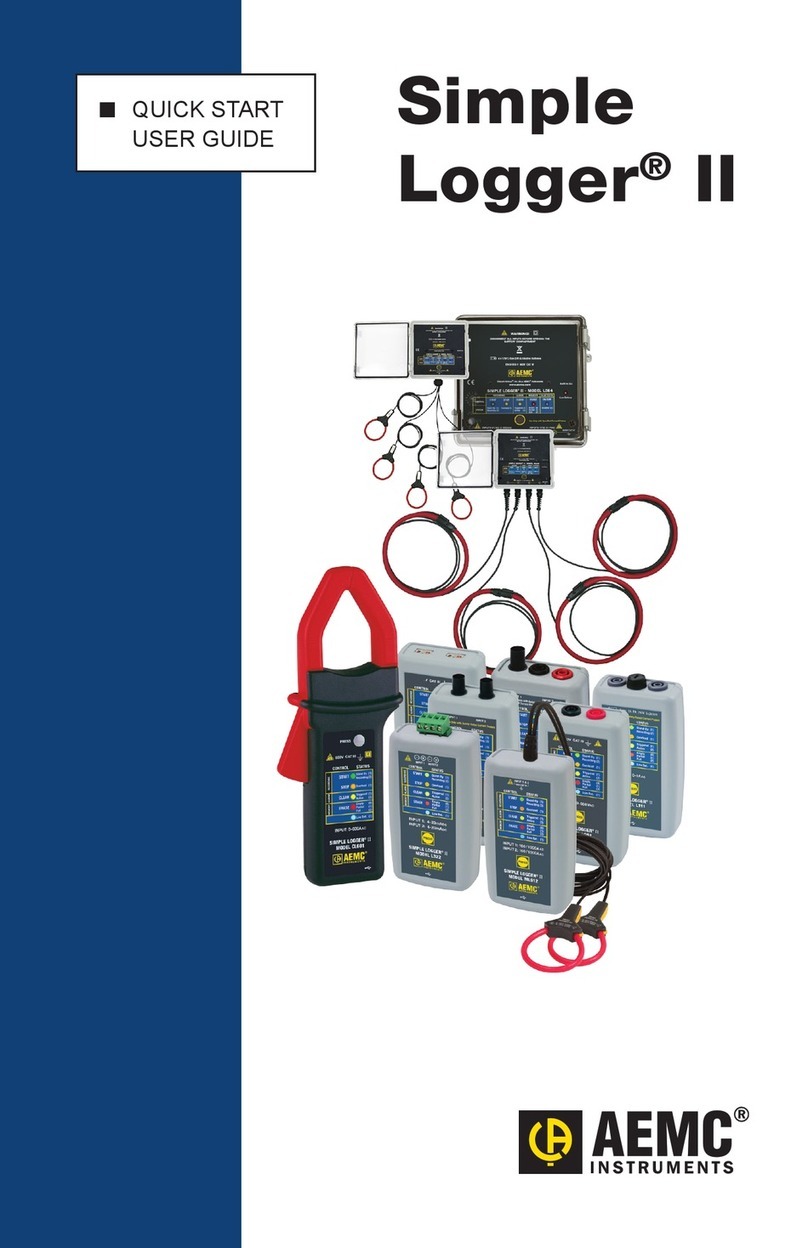
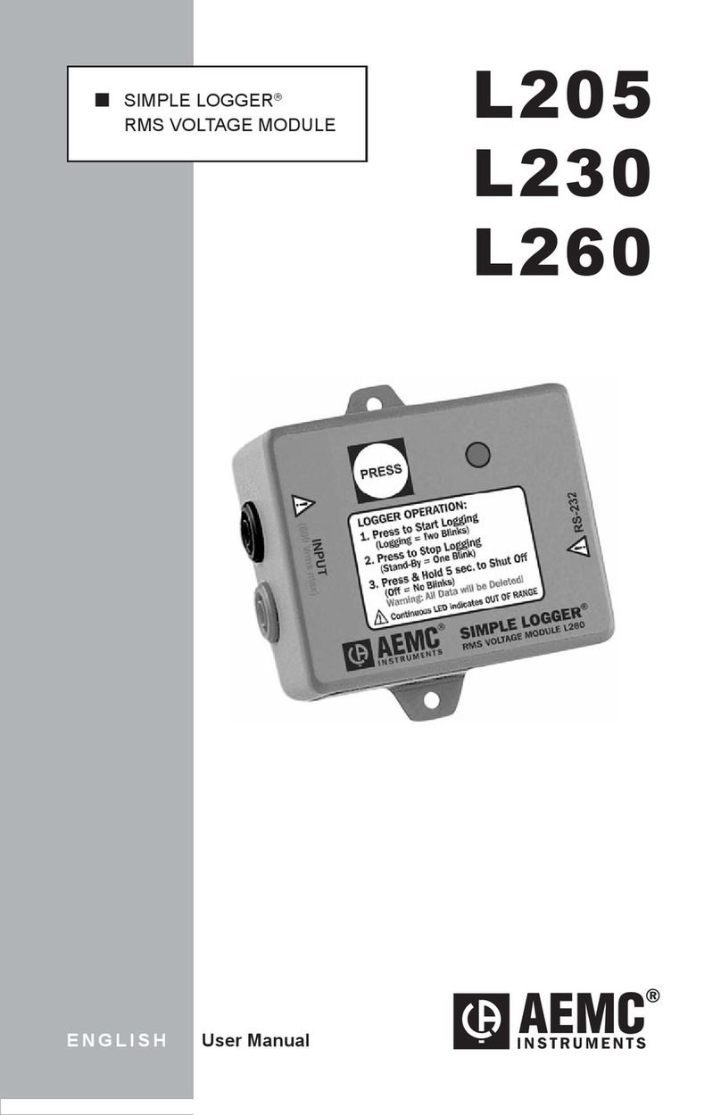
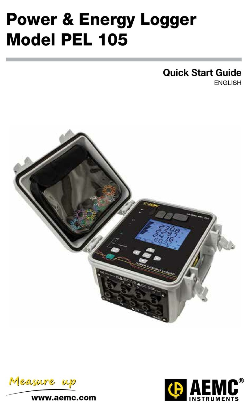
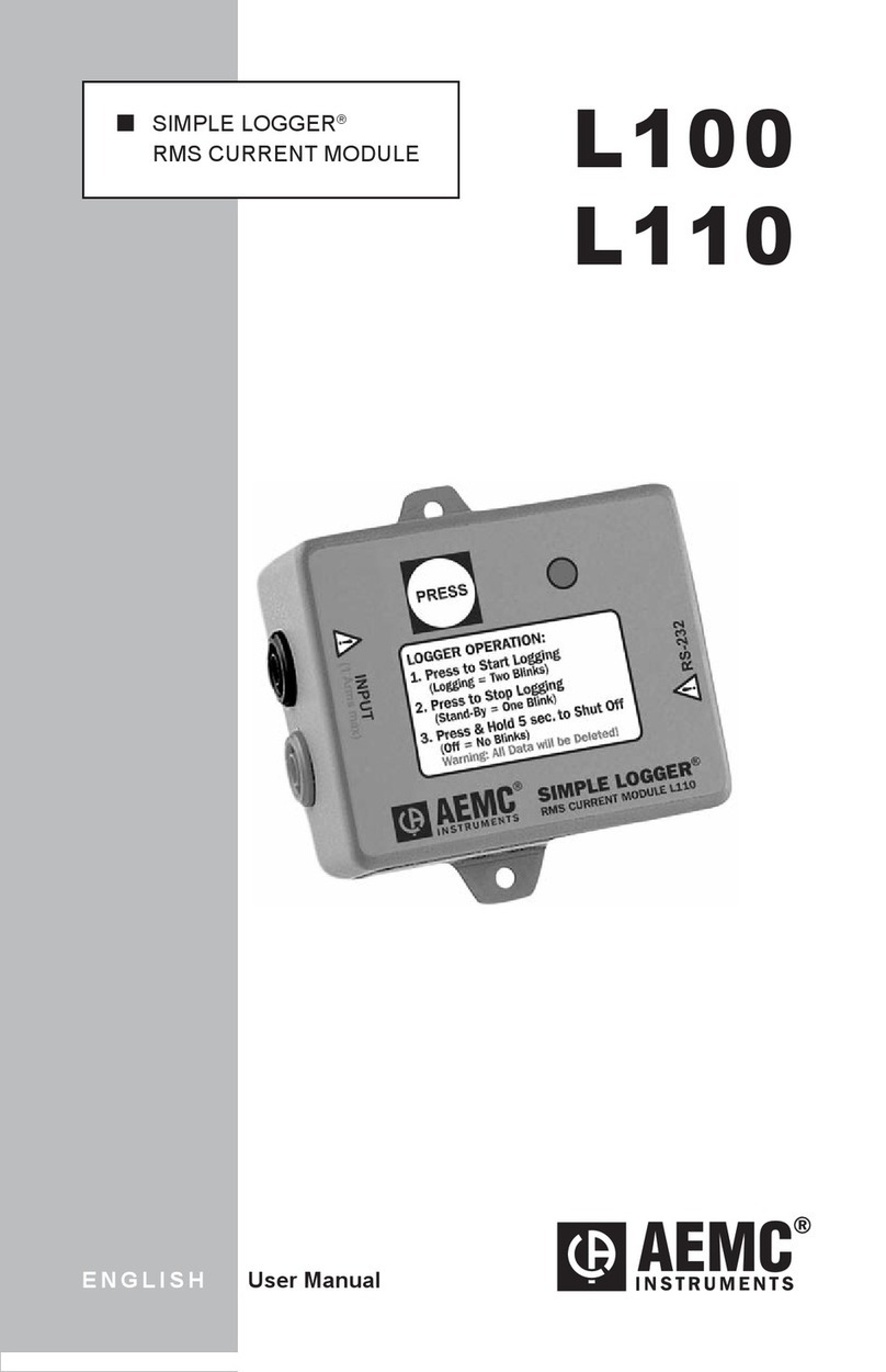
AEMC SENTINEL SDL-V301 User manual

QSENTINEL™
DATA LOGGERS
SDL-V301
SDL-A301
SDL-A302
ENGLISH User Manual

Owner’s Record
The serial number for the Sentinel™ Data Logger is located on the bottom
side of the case. Please record this number and purchase date for your
records.
SENTINEL™ DATA LOGGER
MODEL #: _______________________________________________
SERIAL #: _______________________________________________
PURCHASE DATE: ________________________________________
DISTRIBUTOR: ___________________________________________

Table of Contents
1. INTRODUCTION...................................................................3
Warning ..................................................................................................3
1.1 International Electrical Symbols.....................................................3
1.2 Receiving Your Shipment...............................................................3
1.3 Ordering Information ......................................................................4
1.3.1 Accessories and Replacement Parts ................................4
2. PRODUCT FEATURES ..........................................................5
2.1 Description .....................................................................................5
2.2 Control Features ............................................................................6
2.3 Inputs and Outputs.........................................................................7
3. SPECIFICATIONS.................................................................8
3.1 Sentinel™ Voltage Logger - Model SDL-V301...............................8
3.2 Sentinel™ Current Logger - Model SDL-A301.............................10
3.3 Sentinel™ Current Logger - Model SDL-A302.............................12
4. OPERATION .......................................................................14
4.1 Operating Modes .........................................................................14
4.2 Connecting the Sentinel™ to your Computer ..............................16
4.3 Turning the Unit On ..................................................................16
4.4 Recording Data ............................................................................17
4.4.1 Starting and Stopping a Recording Session....................17
4.5 Downloading Recorded Data .......................................................18
4.6 Erasing Data from Memory ..........................................................18
4.7 Data Storage................................................................................19
4.7.1 Trend Measurements ......................................................19
4.8 Normal Operation.........................................................................20
4.8.1 Normal Operating Environment.......................................20
4.9 Reset Button Operation ...............................................................22
4.10 Synopsis of Operation..................................................................24
5. DATAVIEW® SOFTWARE.....................................................27
5.1 DataView® Software Installation...................................................27
5.2 Installing the Sentinel™ USB drivers ...........................................34
Sentinel™ Data Loggers
3
5.3 Connecting to the Sentinel™ Logger ...........................................40
5.4 Using the Sentinel Control Panel .................................................42
5.5 Conguring the Sentinel™ Logger...............................................45
5.5.1 Setting Recording Options ..............................................46
5.5.2 Setting Format Options ...................................................52
5.5.3 Conguring and Recording Data .....................................54
5.6 Displaying Real-time Status Information......................................57
5.7 Resizing and Saving Real-time Window Layouts ........................59
5.8 Displaying Real-time Waveform Graphs......................................60
5.9 Displaying Real-time Harmonic Bar Graphs ................................62
5.10 Displaying Real-time Harmonic Text Summary............................63
5.11 Displaying a Real-time Trend Graph............................................64
5.12 Saving Real-time Measurements.................................................65
5.12.1 Saving Waveforms and Harmonics .................................65
5.12.2 Saving Trend Graphs ......................................................68
5.13 Downloading Recorded Instrument Data .....................................69
5.14 Sentinel™ Logger Templates.......................................................70
6. MAINTENANCE..................................................................75
6.1 Battery Installation .......................................................................75
APPENDIX A: TROUBLESHOOTING .......................................76
APPENDIX A: GLOSSARY .......................................................77
Repair and Calibration.................................................................................79
Technical and Sales Assistance ..................................................................79
Limited Warranty .........................................................................................80
Warranty Repairs.........................................................................................80

Sentinel™ Data Loggers
3
CHAPTER 1
INTRODUCTION
Warning
These safety warnings are provided to ensure the safety of person-
nel and proper operation of the instrument.
• Read the instruction manual completely and follow all the safety
information before attempting to use or service this instrument.
• Never exceed the maximum working voltage ratings given.
• NEVER open the back of the instrument while connected to any
circuit or input.
• Always inspect the instrument accessories and leads prior to use.
Replace any defective parts immediately with factory parts.
1.1 International Electrical Symbols
This symbol signies that the instrument is protected by double or
reinforced insulation. Use only specied replacement parts when
servicing the instrument.
This symbol on the instrument indicates a WARNING and that the
operator must refer to the user manual for instructions before oper-
ating the instrument. In this manual, the symbol preceding instruc-
tions indicates that if the instructions are not followed, bodily injury,
installation/sample and product damage may result.
Risk of electric shock. The voltage at the parts marked with this
symbol may be dangerous.
1.2 Receiving Your Shipment
Upon receiving your shipment, make sure that the contents are consistent
with the packing list. Notify your distributor of any missing items. If the equip-
ment appears to be damaged, le a claim immediately with the carrier and
notify your distributor at once, giving a detailed description of any damage.
Save the damaged packing container to substantiate your claim.

4
Sentinel™ Data Loggers
5
1.3 Ordering Information
Sentinel™ Voltage Logger Model SDL-V301
(3-Channel, 600VAC) ......................................................... Cat. #2134.10
Includes a USB cable, DataView® CD-ROM, user manual and warranty card.
Sentinel™ Current Logger Model SDL-A301
(3-Channel, 1000AAC) ....................................................... Cat. #2134.15
Includes a USB cable, DataView® CD-ROM, user manual and warranty card.
Sentinel™ Current Logger Model SDL-A302
(3-Channel, 3000AAC) ....................................................... Cat. #2134.16
Includes a USB cable, DataView® CD-ROM, user manual and warranty card.
1.3.1 Accessories and Replacement Parts
Set of black and red leads with alligator clips.................... Cat. #2118.51
NEW:
Order Accessories and Replacement Parts Directly Online
Check our storefront at www.aemc.com for availability

4
Sentinel™ Data Loggers
5
CHAPTER 2
PRODUCT FEATURES
2.1 Description
The Sentinel™ Data Logger Models SDL-V301, SDL-A301 and SDL-A302
are battery powered, three channel recording devices with an alkaline
battery pack. Line tracking is performed such that 64 samples over one
line cycle are taken. Frequency tracking is performed over the range of
±3Hz around the nominal line frequency (50 or 60Hz). Power Quantity
and Power Quality measurements are calculated from these 64 samples
for all input channels (note that Power Quality is only available from the
Sentinel™ Control Panel application).
The Sentinel™ records RMS for each of the inputs at a rate of up to four
times per second. Measurements for each channel are taken sequentially.
This means that while the instrument is taking samples on one channel
the other channels are ignored. The measurement process is performed
no more that four times per second. RMS calculations are performed on
a single line cycle. This means that the inputs and line cycles are ignored
between measurement intervals.
The main advantage of the logger is its ability to perform a variety of
recording tasks with easy and intuitive setup from a computer using the
DataView® Software.
Analog information on the input is sampled and converted to a digital
signal. This digital signal is processed and stored along with scale and
time information. An optically isolated Universal Serial Bus (USB) port
provides for the transfer of data from internal memory to the computer for
analysis. Figure 2-1 shows a block diagram of the logger.
Figure 2-1. Data Logger Block Diagram.

6
Sentinel™ Data Loggers
7
2.2 Control Features
1
2
3
Figure 2-2. Key Components and Features
1. Control Button (Record Start/Stop)
This button marked “PRESS” selects the mode of operation. The
logger has three modes: RECORD, STANDBY and OFF. Use this
button to start or stop recording and erase recording memory.
2. Three LED Indicators
• RED LED: Indicates the status of battery voltage
• YELLOW LED: Indicates the status of the memory
LED OFF: No data in memory
LED Single Blink: Memory is partially lled
LED Double Blink: Memory is full
• GREEN LED: Indicates the mode of operation
(STANDBY, RECORD or OFF)
LED OFF: Logger is turned off
LED Single Blink: Logger is in Standby Mode (and not recording)
LED Double Blink: Logger is in Record Mode
Note: All three LEDs single blink simultaneously in case of an over-
load (≥10% above range) at the input if the unit is in power-on status.

6
Sentinel™ Data Loggers
7
3. Female Type B USB Connector
4. Reset Button (not shown)
This button resets the CPU.
The Reset Button is located inside the instrument under the shield.
Remove the rear cover and insert a small tool, such as a pen, through
the hole in the shield to activate it. Do not press the Reset Button
under normal operation.
If the Reset Button is pressed when the Logger is recording, it will stop
recording and data in the memory may be lost.
2.3 Inputs and Outputs
The Sentinel™ Data Logger voltage models have voltage leads and clips.
The current models have permanently attached AmpFlex™ current probes.
The logger is also supplied with a male/male USB cable used for data
transmission from the Sentinel™ Data Logger to your computer.

8
Sentinel™ Data Loggers
9
CHAPTER 3
SPECIFICATIONS
3.1 Sentinel™ Voltage Logger - Model SDL-V301
ELECTRICAL
All measurements are TRMS based on 64 samples per cycle.
Range: 0 to 600VAC; 0 to 850VDC
Display Resolution: 0.1V
Accuracy: ± (0.25% of Reading + 0.6V) from 85 to 600VAC (850VDC)
± (1.0% of Reading + 0.6V) from 5 to 85VAC/DC
Accuracy specications apply in the 23°C ± 5°C (30 to 50% RH) range. Add 200 ppm/°C from -10° to
18°C and 28° to 50°C to all accuracy specications. Sinusoidal voltage with frequency 50 or 60Hz ± 3Hz.
Calibration cycle is 1 year.
POWER
Power Source: Four 1.5V, C size alkaline batteries.
Operating Time (@ 25°C):
Storage Rate < 2 Sec: 100 hrs
Storage Rate 5 Sec, 6 Sec: 20 days
Storage Rate 10 Sec, 15 Sec: 45 days
Storage Rate > 30 Sec: 90 days
An internal lithium battery (>2.8V) provides additional memory back up for
up to 30 days.
If the unit is connected to DataView® via PC, the operating time is 100
hours regardless of the storage rate.

8
Sentinel™ Data Loggers
9
RECORDING
Storage Rate: 250ms to 12 hrs
Recording Session Length: 1 minute to 8 weeks selectable from table
or user programmable from computer
Total Memory: Record 480,000 events (Size: 1MB)
Date and Time: MM/DD/YY, DD/MM/YY, hh:mm:ss.sss
(24hr and AM/PM)
Storage Technique: Start/Stop, FIFO, XRM™ (Extended Recording Mode)
INPUT
Three sets of recessed banana jacks for voltage inputs for differential
measurements. 64-samples/cycle are taken to calculate TRMS value for
each input.
INTERFACE
Output: USB 2.0 Compliant
Isolation: Optically isolated, 5.5kVrms maximum
Speed: 115.2 kbps
MECHANICAL
Dimensions: 6.73 x 4.76 x 2.17" (171 x 121 x 55mm)
Weight: 1.8 lbs (0.8kg) including the batteries
Case: Polycarbonate UL94-V2
ENVIRONMENTAL
Operating Temperature: 14° to 122°F (-10° to 50°C)
Storage Temperature: -4° to 140°F (-20° to 60°C)
Relative Humidity: Up to 85% @ 95°F (35°C), Non-condensing
Altitude: 2000m
SAFETY
Safety: 600V Cat. III, 300V Cat. IV
Vibration: IEC 68-2-6 (1.5mm 10Hz-55Hz)
Shock: IEC 68-2-27 (30G)
Drop: IEC 68-2-32 (1m)

10
Sentinel™ Data Loggers
11
3.2 Sentinel™ Current Logger - Model SDL-A301
ELECTRICAL
All measurements are TRMS based on 64 samples per cycle.
Range: 5 to 1000A
Display Resolution: 0.1A
Accuracy: ± (1.0% of Reading + 1.0A) from 100 to 1000A
± (1.0% of Reading + 1.2A) from 5 to 100A
Accuracy specications apply in the 23°C ± 5°C (30 to 50% RH) range. Add 300 ppm/°C from -10° to
18°C and 28° to 50°C to all accuracy specications. Conductor must be centered in the sensor. Continu-
ous magnetic eld <40 A/m (Earth Magnetic Field). No external electrical or alternating magnetic eld is
present. Sinusoidal current with frequency 50/60Hz ± 3Hz for >60A and 50/60Hz for <60A. Calibration
cycle is 1 year.
POWER
Power Source: Four C size alkaline batteries.
Operating Time (@ 25°C):
Storage Rate <2 Sec: 100 hrs
Storage Rate 5 Sec, 6 Sec: 15 days
Storage Rate 10 Sec, 15 Sec: 25 days
Storage Rate >30 Sec: 45 days
An internal lithium battery (>2.8V) provides additional memory back up for
up to 30 days.
If the unit is connected to DataView® via PC, the operating time is 100
hours regardless of the storage rate.
RECORDING
Storage Rate: 250ms to 12 hrs
Recording Session Length: 1 minute to 8 weeks selectable from table
or user programmable from computer
Total Memory: Record 480,000 events (Size: 1MB)
Date and Time: MM/DD/YY, DD/MM/YY, hh:mm:ss.sss
(24hr and AM/PM)
Storage Technique: Start/Stop, FIFO, XRM™ (Extended Recording Mode)

10
Sentinel™ Data Loggers
11
INPUT
Three current input using integrally wired exible AmpFlex™ sensors. 64
samples/cycle are taken to calculate TRMS value for each input.
INTERFACE
Output: USB 2.0 Compliant
Isolation: Optically isolated, 5.5kVrms maximum
Speed: 115.2 kbps
MECHANICAL
Dimensions: 6.73 x 4.76 x 2.17" (171 x 121 x 55mm)
Weight: 3.2 lbs (1.4kg) including the batteries and AmpFlex™ sensors
Case: Polycarbonate UL94-V2
ENVIRONMENTAL
Operating Temperature: 14° to 122°F (-10° to 50°C)
Storage Temperature: -4° to 140°F (-20° to 60°C)
Relative Humidity: Up to 85% @ 95°F (35°C), Non-condensing
Altitude: 2000m
SAFETY
Safety: 600V, Cat. III, 1000A
Vibration: IEC 68-2-6 (1.5mm 10Hz-55Hz)
Shock: IEC 68-2-27 (30G)
Drop: IEC 68-2-32 (1m)

12
Sentinel™ Data Loggers
13
3.3 Sentinel™ Current Logger - Model SDL-A302
ELECTRICAL
All measurements are TRMS based on 64 samples per cycle.
Range: 15 to 3000A
Display Resolution: 0.25A
Accuracy: ± (1.0% of Reading + 1.0A) from 100 to 3000A
± (1.0% of Reading + 1.5A) from 15 to 100A
Accuracy specications apply in the 23°C ± 5°C (30 to 50% RH) range. Add 300 ppm/°C from -10° to
18°C and 28° to 50°C to all accuracy specications. Conductor must be centered in the sensor. Continu-
ous magnetic eld <40 A/m (Earth Magnetic Field). No external electrical or alternating magnetic eld is
present. Sinusoidal current with frequency 50/60Hz ± 3Hz for > 60A and 50/60Hz for < 60A. Calibration
cycle is 1 year.
POWER
Power Source: Four C size alkaline batteries.
Operating Time (@ 25°C):
Storage Rate < 2 Sec: 100 hrs
Storage Rate 5 Sec, 6 Sec: 15 days
Storage Rate 10 Sec, 15 Sec: 25 days
Storage Rate > 30 Sec: 45 days
An internal lithium battery (>2.8V) provides additional memory back up for
up to 30 days.
If the unit is connected to DataView® via PC, the operating time is 100
hours regardless of the storage rate.
RECORDING
Storage Rate: 250ms to 12 hrs
Recording Session Length: 1 minute to 8 weeks selectable from table
or user programmable from computer
Total Memory: Record 480,000 events (Size: 1MB)
Date and Time: MM/DD/YY, DD/MM/YY, hh:mm:ss.sss
(24hr and AM/PM)
Storage Technique: Start/Stop, FIFO, XRM™ (Extended Recording Mode)

12
Sentinel™ Data Loggers
13
INPUT
Three Current input using integrally wired exible AmpFlex™ sensors. 64
samples/cycle are taken to calculate TRMS value for each input.
INTERFACE
Output: USB 2.0 Compliant
Isolation: Optically isolated, 5.5kVrms maximum
Speed: 115.2 kbps
MECHANICAL
Dimensions: 6.73 x 4.76 x 2.17" (171 x 121 x 55mm)
Weight: 3.2 lbs (1.4kg) including the batteries and AmpFlex™ sensors
Case: Polycarbonate UL94-V2
ENVIRONMENTAL
Operating Temperature: 14° to 122°F (-10° to 50°C)
Storage Temperature: -4° to 140°F (-20° to 60°C)
Relative Humidity: Up to 85% @ 95°F (35°C), Non-condensing
Altitude: 2000m
SAFETY
Safety: 600V Cat. III, 300V Cat. IV, 3000A
Vibration: IEC 68-2-6 (1.5mm 10Hz-55Hz)
Shock: IEC 68-2-27 (30G)
Drop: IEC 68-2-32 (1m)

14
Sentinel™ Data Loggers
15
CHAPTER 4
OPERATION
4.1 Operating Modes
The Sentinel™ Logger has three modes: RECORD, STANDBY and OFF.
After the instrument has been turned on, the operating mode of the logger
can be determined by pressing the PRESS button for less than 1.5 seconds.
The GREEN LED indicates the mode of operation:
LED OFF: Logger is turned off
LED Single Blink: Logger is in Standby Mode (and not recording)
LED Double Blink: Logger is in Record Mode
The YELLOW LED will blink depending on the state of recording memory:
LED OFF: No data in memory
LED Single Blink: Memory is partially lled
LED Double Blink: Memory is full
In the STANDBY and OFF modes, the logger retains recorded information
for transfer to a computer.
Both of these modes have low power states, which require very little
power from the battery. The LEDs will not blink at this time. By using these
low power states the instrument can be programmed to start recording at
some time in the future without draining the batteries. The instrument can
also record for very long periods.
While in a low power state, a button press is required before further use
of the instrument. For this reason, a short button press should be issued
before attempting any other button control operations.
When in the STANDBY mode, the unit enters the low power state if the
button is not pressed for ve minutes. It will remain in this state until either
the button is pressed or the internal clock reaches the start time for a
scheduled recording.
When in the RECORD mode, the instrument will enter the low power state
provided the storage period is one second or greater and the button has
not been pressed for ve minutes. If the recording storage rate is faster
than once per second the unit will not power down between sample sets.

14
Sentinel™ Data Loggers
15
Operations are determined by the length of time the control button is
pressed. The lighting of each LED in sequence provides a visual indication
that a required amount of time (for each operation) has been reached.
The following table illustrates the operations that can be performed while
in each of the three modes.
Mode Operation to be
Performed
Press
Duration
(seconds)
Indication
(LEDs that light) Notes
Off Turn On 5 RED, GREEN and YELLOW
simultaneously (1)
Standby
Turn Off 5 GREEN, then RED (2) (3)
Start Recording 1.5 GREEN
Erase Memory 10 GREEN, then RED,
then YELLOW (2) (4) (5)
Recording Stop Recording 3 GREEN and RED
simultaneously (1)
Notes:
(1) LEDs light at the same time.
(2) LEDs light one at a time in sequence.
(3) GREEN lights after 1.5 seconds, RED lights after 3 seconds.
(4) GREEN lights after 1.5 seconds, RED lights after 3 seconds and YELLOW lights
after 10 seconds.
(5) Hold the button for 10 seconds. Release it. Press again within 3 seconds and hold
for 10 seconds.
NOTE: If the input to the logger exceeds 10% over the range and the logger
is powered on, all three LEDs will blink at a rate of one per second.

16
Sentinel™ Data Loggers
17
4.2 Connecting the Sentinel™ to your Computer
DO NOT CONNECT THE SENTINEL TO THE COMPUTER
UNTIL THE SOFTWARE & DRIVERS HAVE BEEN INSTALLED.
Figure 4-1 shows a typical hook-up. The Sentinel™ Data Logger utilizes an
optically isolated USB communication port.
The manual for your computer should indicate where to nd the USB port.
Figure 4-1. Connecting the Data Logger to the Computer’s USB port.
You may leave the logger connected to the computer during a recording
session. However, additional battery drainage will occur to support the
active USB connection.
4.3 Turning the Unit On
The Sentinel™ Data Logger can be turned ON by performing one of the
following:
• Press and hold the PRESS button for approximately 5 seconds.
• Connect the unit to the USB connection using the DataView® software
The logger will remain ON while a communication link with DataView®
is active (provided sufcient battery power is available during the com-
munication session).
The unit has been turned ON successfully when the RED, YELLOW and
GREEN LEDs light up. At this time you can release the PRESS button.
The unit is now in the STANDBY mode.
The instrument contains protection circuitry to prevent it from being turned
on when the battery voltage is below 3.8V.

16
Sentinel™ Data Loggers
17
There are two thresholds for the battery voltage depending on how the
instrument is turned ON (either button press or DataView®) and the record-
ing state that it is in.
•
If the unit is turned ON from a button press, the threshold is
4.3V. This means that if the unit is turned on and the battery voltage is
below 4.3V, the RED LED will double-blink and the unit will turn off.
• If the unit is turned ON via DataView®, the threshold is 3.8V.
This means that the instrument can be turned on via DataView®
as long as the battery voltage is above 3.8V. If the instrument is
recording, it will continue to record until the battery voltage falls
below 3.8V.
4.4 Recording Data
4.4.1 Starting and Stopping a Recording Session
NOTE: The Sentinel™ Data Logger is factory congured and may be altered
to t the users needs (see § 5.5 - Conguring the Sentinel™ Logger).
Once a conguration is written to the Sentinel, the logger will no longer
need to be connected to DataView® to start the congured recording.
When data is stored in the memory, the user may download the informa-
tion onto a hard-disk (see § 5.13 - Downloading Recorded Instrument
Data).
To Start Recording:
NOTE: A new recording may not be started if the memory is full.
1. Connect the inputs to the measurement source.
2.
Make sure the logger is in STANDBY mode (GREEN LED single-blinks).
3. Press the PRESS button for longer than 1.5s but less than 3s to start
recording.
4. Verify that the GREEN LED double-blinks to ensure that the logger is
recording.
Warning: If, during a recording, the GREEN LED remains ON,
the Sentinel™ Data Logger is in a fault condition. Disconnect
immediately (the logger will not record and the battery will
drain faster).

18
Sentinel™ Data Loggers
19
To Stop Recording:
1. Push the PRESS button for >3s and <5s. The RED and GREEN LED
will turn on simultaneously.
2. The GREEN LED will change from a double-blink to a single-blink,
indicating STANDBY mode.
The data will be retained, even if the instrument is turned OFF. The
recorded data may be downloaded to a hard-disk.
4.5 Downloading Recorded Data
Recorded measurements stored in the instrument are transferred to a
database on a hard-disk via the download command in the Sentinel
Control Panel. For complete instructions on downloading data, see §5.13
- Downloading Recorded Instrument Data.
4.6 Erasing Data from Memory
Erasing data from the instrument’s memory can only be performed while
in the STANDBY mode.
WARNING: Data will be permanently lost by performing this
procedure.
There are two ways to erase the memory:
Erasing the Memory using the PRESS Button:
1. Press and hold the PRESS button for >10s. This will arm the instru-
ment for an erase operation (when not in record mode).
2.
Once the button has been held long enough to arm the unit, the
YELLOW LED will light. At this time you can release the
PRESS
button.
3. Press and hold the PRESS button for another 10s within 3 seconds of
arming the erase operation.
4.
Once the button has been held long enough to erase memory, the
YELLOW LED will light. At this time you can release the PRESS
button.
5. As the memory is being erased the unit will cycle through the three
LEDs until the operation has nished.
This manual suits for next models
2
Table of contents
Other AEMC Data Logger manuals

AEMC
AEMC L205 User manual

AEMC
AEMC PEL 52 User manual

AEMC
AEMC Simple Logger II User manual

AEMC
AEMC PEL 102 User manual

AEMC
AEMC Simple Logger II User manual

AEMC
AEMC L452 User manual

AEMC
AEMC PEL 102 User manual

AEMC
AEMC Simple Logger II Series User manual

AEMC
AEMC L452 User manual

AEMC
AEMC PEL 102 User manual
Popular Data Logger manuals by other brands

Capetti Elettronica
Capetti Elettronica WSD12-EVTT user manual

Calypso Instruments
Calypso Instruments ULTRASONIC Portable Solar user manual

Newland
Newland NLS-MT70 user guide

Circutor
Circutor PV-Monitor-M instruction manual

Reed Instruments
Reed Instruments R8100SD instruction manual

Colorado time systems
Colorado time systems Dolphin user guide