AEMC 193-24-BK User manual

Current Probes & Sensors
(For Power Quality Meters & Power Energy Loggers)
193-24-BK
193-36-BK
196A-24-BK
MA193-10-BK
MA193-14-BK
MN93-BK
MN193-BK
MR193-BK
SL261
SR193-BK
ENGLISH User Manual

Copyright © Chauvin Arnoux®, Inc. d.b.a. AEMC®Instruments. All rights reserved.
No part of this documentation may be reproduced in any form or by any means (including electronic storage and retrieval or
translation into any other language) without prior agreement and written consent from Chauvin Arnoux®, Inc., as governed
by United States and International copyright laws.
Chauvin Arnoux®, Inc. d.b.a. AEMC®Instruments
15 Faraday Drive • Dover, NH 03820 USA
Tel: (800) 945-2362 or (603) 749-6434 • Fax: (603) 742-2346
This documentation is provided “as is,” without warranty of any kind, express, implied, or otherwise. Chauvin Arnoux®,
Inc. has made every reasonable eort to ensure that this documentation is accurate; but does not warrant the accuracy or
completeness of the text, graphics, or other information contained in this documentation. Chauvin Arnoux®, Inc. shall not be
liable for any damages, special, indirect, incidental, or inconsequential; including (but not limited to) physical, emotional or
monetary damages due to lost revenues or lost prots that may result from the use of this documentation, whether or not
the user of the documentation has been advised of the possibility of such damages.

Thank you for purchasing an AEMC current probe.
For best results from your instrument and for your safety, read the enclosed
operating instructions carefully and comply with the precautions for use. These
products must be only used by qualied and trained users.
WARNING, risk of DANGER! The operator must refer to these instructions
whenever this danger symbol appears.
CAUTION! Risk of electric shock. The voltage at the parts marked with this
symbol may be dangerous.
Application or withdrawal authorized on conductors carrying dangerous voltages.
Type A current sensor as per IEC 61010-2-032.
Must not be applied to or removed from conductors at dangerous voltages.
Type B current sensor as per IEC 61010-2-032.
Equipment is protected by double insulation.
Battery
Important instructions to read and to fully understand.
Useful information or tip to read.
The CE marking guarantees conformity with European directives and with
regulations covering EMC.
The trash can with a line through it means that in the European Union, the
product must undergo selective disposal for the recycling of electric and
electronic material, in compliance with Directive WEEE 2002/96/EC.
Denition of Measurement Categories (CAT)
CAT IV Measurement category IV corresponds to measurements taken at the
source of low-voltage installations.
Example: power feeders, counters and protection devices.
CAT III Measurement category III corresponds to measurements on building
installations.
Example: distribution panel, circuit-breakers, machines or xed indus-
trial devices.
CAT II Measurement category II corresponds to measurements taken on cir-
cuits directly connected to low-voltage installations.
Example: power supply to domestic electrical appliances and portable
tools.

PRECAUTIONS BEFORE USE
The protection assured by the current probe can be compromised if it is used in a
way that is not recommended by the manufacturer.
■Comply with the rated maximum voltage and current, and the measurement
category. Do not use the current probe on networks where the voltage or
category exceeds those specied.
■Comply with the conditions of use (e.g. temperature, humidity, altitude, degree
of pollution, location).
■Do not use the current probe if its housing is open, deteriorated, or incorrectly
reassembled. Before each use, check the integrity of the insulation of the unit,
jaws, clamps, housing, and leads.
■Do not subject the current probe to water or other liquids.
■Keep the jaw contacts of the clamp absolutely clean.
■Use suitable personal protective equipment when hazardous voltages may be
accessible in the installation where the measurement is made.
■Any repairs must be carried out by accredited skilled personnel.

Current Probes & Sensors for Power Quality Meters and Power Energy Loggers
3
Table of Contents
1. INTRODUCTION .....................................................................4
1.1 Receiving Your Shipment......................................................................4
1.2 Ordering Information.............................................................................4
2. PRODUCT FEATURES ............................................................5
2.1 Control Features...................................................................................5
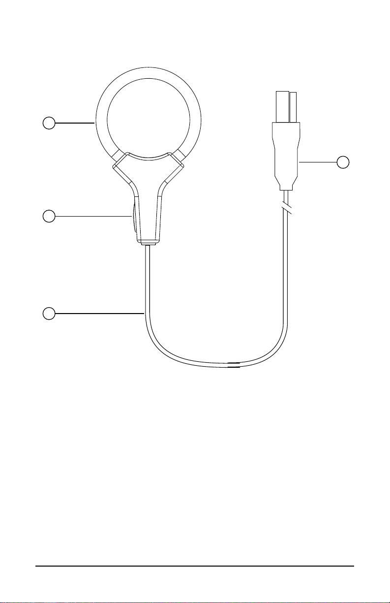
2.1.1 AmpFlex®Models 193-24-BK, 193-36-BK & 196-24-BK ..........5
2.1.2 MiniFlex®Model MA193-BK .....................................................6
2.1.3 AC/DC Current Probe Model J93-BK .......................................7
2.1.4 AC Current Probe Models MN93-BK & MN193-BK..................8
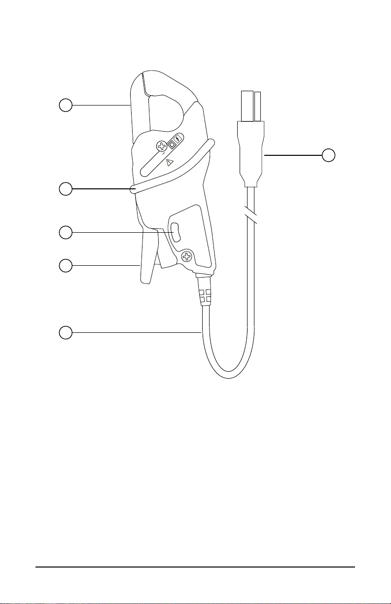
2.1.5 AC Current Probe Model MR193-BK........................................9
2.1.6 AC Current Probe Model SL261.............................................10
2.1.7 AC Current Probe Model SR193-BK ......................................11
3. OPERATION..........................................................................12
4. SPECIFICATIONS .................................................................14
4.1 Electrical .............................................................................................14
4.2 Environmental.....................................................................................15
4.3 Mechanical..........................................................................................15
4.4 Safety..................................................................................................16
5. MAINTENANCE ....................................................................17
5.1 Cleaning..............................................................................................17
5.2 Battery Replacement ..........................................................................17
5.2.1 Model MR193-BK ...................................................................17
5.2.2 Model SL261 ..........................................................................17
5.2.3 Model J93-BK.........................................................................18
5.3 Repair and Calibration........................................................................19
5.4 Technical and Sales Assistance..........................................................19
5.5 Limited Warranty.................................................................................20
5.6 Warranty Repairs................................................................................20

4Current Probes & Sensors for Power Quality Meters and Power Energy Loggers
1. INTRODUCTION
1.1 Receiving Your Shipment
Upon receiving your shipment, make sure that the contents are consistent with the
packing list. Notify your distributor of any missing items. If the equipment appears
to be damaged, le a claim immediately with the carrier and notify your distributor
at once, giving a detailed description of any damage. Save the damaged packing
container to substantiate your claim.
1.2 Ordering Information
NOTE: The current probes in this manual are compatible only with AEMC®Power
Analyzers (see § 4 for meter compatibility).
AmpFlex®Sensor 24" Model 193-24-BK ..........................................Cat. #2140.34
AmpFlex®Sensor 36" Model 193-36-BK ..........................................Cat. #2140.35
AmpFlex®Sensor 24” Model 196A-24-BK........................................Cat. #2140.75
MiniFlex®Sensor 10" Model MA193-10-BK......................................Cat. #2140.48
MiniFlex®Sensor 14" Model MA193-14-BK......................................Cat. #2140.50
AC/DC Current Probe Model J93-BK ....................... Discontinued October 2021
AC Current Probe Model MN93-BK..................................................Cat. #2140.32
AC Current Probe Model MN193-BK................................................Cat. #2140.36
AC Current Probe Model MR193-BK................................................Cat. #2140.28
AC Current Probe Model SR193-BK ................................................Cat. #2140.33
AC/DC Current Probe Model SL261* ...............................................Cat. #1201.51
* Adapter for SL261 - BNC Adapter ............................................Cat. #2140.40

Current Probes & Sensors for Power Quality Meters and Power Energy Loggers
5
2. PRODUCT FEATURES
2.1 Control Features
2.1.1 AmpFlex
®
Models 193-24-BK, 193-36-BK & 196A-24-BK
2
3
4
1
1. Flexible sensor
2. Sensor opening connector
3. Shielded lead
4. Custom 4-pin input connector (available standard or IP 67 compliant,
depending on instrument)

6Current Probes & Sensors for Power Quality Meters and Power Energy Loggers
2.1.2 MiniFlex®Model MA193-BK
2
3
4
1
1. Flexible sensor
2. Sensor opening device
3. Shielded lead
4. Custom 4-pin input connector

Current Probes & Sensors for Power Quality Meters and Power Energy Loggers
7
2.1.3 AC/DC Current Probe Model J93-BK
1
2
4
5
6
3
5000A
500A
ZERO
Stop
Test
MARCHE
SORTIE
ZERO
ON
OFF
300 V CAT IV
600 V CAT III
1. Jaws
2. 4-point CA connector
3. Safety guard
4. Zero adjustment knob
5. Power ON/ Low battery indicator
6. Three-position switch: ON, OFF, battery test

8Current Probes & Sensors for Power Quality Meters and Power Energy Loggers
2.1.4 AC Current Probe Models MN93-BK & MN193-BK
200V CAT IV
600V CAT III 200A
5
4
2
3
6
1
1. Jaws
2. Protective guard
3. Two-position range switch (MN193-BK only)
4. Jaw opening lever
5. Shielded lead
6. Custom 4-pin input connector

Current Probes & Sensors for Power Quality Meters and Power Energy Loggers
9
2.1.5 AC Current Probe Model MR193-BK
5
2
4
3
7
6
1
1. Jaws
2. Protective guard
3. Jaw opening lever
4. Two-position range switch
5. Shielded lead
6. Zero adjustment
7. Custom 4-pin input connector

10 Current Probes & Sensors for Power Quality Meters and Power Energy Loggers
2.1.6 AC Current Probe Model SL261
2
3
5 6
4
1
1. Jaws
2. Zero adjust knob
3. Range selection switch
4. Battery compartment screw
5. Battery compartment cover
6. BNC Adapter (sold separately - Cat. #2140.40)

Current Probes & Sensors for Power Quality Meters and Power Energy Loggers
11
2.1.7 AC Current Probe Model SR193-BK
4
2
3
5
1
1. Jaws
2. Protective guard
3. Jaw opening lever
4. Shielded lead
5. Custom 4-pin input connector

12 Current Probes & Sensors for Power Quality Meters and Power Energy Loggers
3. OPERATION
The current probes and exible sensors are used to measure the current owing
in a conductor or bus bar without opening the circuit. They also insulate the user
from dangerous voltages in the circuit.
The choice of current probe or sensor to be used depends on the amperage to be
measured and the diameter of the cables or size of the bus bar.
■For three-phase measurements, use the color-coded ID markers to associate
a color for each current input to match the phase identiers on the measured
system.
IMPORTANT NOTE: Always connect the probes or sensors
with the indicating arrows pointing toward the load.
For Example Only (instrument’s will vary):
■Connect the current probe or sensor to the current terminals of the instrument.
For MR193-BK and SL261 Probes:
■MR193-BK: Set the switch to 1mV/A; the ON indicator will light up.
SL261: Set the switch to 10mV or 100mV/A; the ON indicator will light up.
■Connect the probe to the instrument.
■Adjust the zero by turning the potentiometer with no conductor in the jaws of the
clamp.
■When the measurement is nished, turn the probe switch to OFF.

Current Probes & Sensors for Power Quality Meters and Power Energy Loggers
13
For Probes:
■Press the jaw opening lever on the probe to open the jaws.
■Clamp the probe around the conductor to be tested. For best results, center the
conductor in the jaws of the clamp.
I
For AmpFlex® and MiniFlex® Sensors:
■AmpFlex®: Press simultaneously on both sides of the opening connector.
■MiniFlex®: Press the opening device to open the exible sensor.
■Clamp the sensor around the conductor to be tested. For best results, center the
conductor in the jaws of the clamp.
■Close the sensor by pushing the moving part into the connector until it clicks.
NOTE: For details of the measurement configuration and technical specifications,
refer to the user manual of the instrument the current probe is being used with.

14 Current Probes & Sensors for Power Quality Meters and Power Energy Loggers
4. SPECIFICATIONS
4.1 Electrical
NOTE: The measurement ranges specied are for the probes and sensors.
In some cases, they may dier from the ranges that can be measured by the
instrument with which they are used with.
For complete specifications: Refer to the product user manual that is supplied
with each compatible instrument.
Model Measurement Range Compatibility
AmpFlex®193-24-BK (1)
24"(610mm)
200mA to 10kAAC (2)
(12,000A) (3) All PowerPads and PEL 100 Series
AmpFlex®193-36-BK (1)
36"(910mm)
200mA to 10kAAC (2)
(12,000A) (3) All PowerPads and PEL 100 Series
AmpFlex®196A-24-BK (1)
24"(610mm)
200mA to 10kAAC (2)
(12,000A) (3) 8435, 8436, and PEL 105
MiniFlex®MA193-BK (1)
10"(250 mm)
200mA to 3000A
(10,000A peak) All PowerPads and PEL 100 Series
MiniFlex®MA193-BK (1)
14"(355 mm)
200mA to 3000A
(10,000A peak) All PowerPads and PEL 100 Series
J93-BK 50 to 3500;
50 to 5000 (DC only)
8333, 8336, 8435, 8436 and
PEL 100 Series
MN93-BK 2 to 240AAC
(I >200A not permanent) All PowerPads and PEL 100 Series
MN193-BK 5A: 0.005 to 6AAC
100A: 0.1 to 120AAC All PowerPads and PEL 100 Series
MR193-BK 10 to 1000AAC;
10 to 1300APEAK AC+DC All PowerPads and PEL 100 Series
SL261 100mV/A: 100mA to 10A peak
10mV/A: 1 to 100A peak All PowerPads and PEL 100 Series
SR193-BK 1 to 1200AAC
(I > 1000A not continuously) All PowerPads and PEL 100 Series
(1) 10 to 6500AAC for Model 8435; 100mA to 6500A for Model 8436
(2) 200mA to 10,000A measurement range for the PEL 100 Series.
(3) 12,000A is specied for the PEL 100 Series only.
Battery: 9V Alkaline NEDA 1604A, 6LR61
Battery Life: MR193-BK - 100H typical
SL261 - 55H typical
J93-BK - 70H typical
NOTE: Battery life is twice the typical value when using Lithium batteries

Current Probes & Sensors for Power Quality Meters and Power Energy Loggers
15
4.2 Environmental
Indoor use.
Operating Temperature: 14° to 131°F (-10° to 55°C); 10% to 85% RH
Storage Temperature: -40° to 158°F (-40° to 70°C); 10% to 90% RH
Degree of pollution: 2
Altitude: < 2000 m
4.3 Mechanical
Model Lead Length
(nominal)
Clamping
Diameter Dimensions Weight
AmpFlex®193-24-BK
24"(610mm) 10 ft (3m) 7.64"(190mm)
6.6 x 6.2 x 0.98"
(170 x 158 x
25mm)
7.7 oz
(270g)
AmpFlex®193-36-BK
36"(910mm) 10 ft (3m) 11.46"(290mm)
11 x 10.4 x 0.98"
(280 x 265 x
25mm)
9.5 oz
(220g)
AmpFlex®196A-24-BK
24"(610mm) 10 ft (3m) 7.64"(190mm)
6.6 x 6.2 x 0.98"
(170 x 158 x
25mm)
7.7 oz
(270g)
MiniFlex®
MA193 -10-BK
10"(250mm)
10 ft (3m) 2.75"(70mm) 4.0 x 2.5 x 1.1"
(103 x 64 x 28mm)
1.94 oz
(55g)
MiniFlex®
MA193-14-BK
14"(350mm)
10 ft (3m) 3.94"(100mm) 4.0 x 2.5 x 1.1"
(103 x 64 x 28mm)
2.11 oz
(60g)
J93-BK 10 ft (3m) 2.84"(72mm)
13.23 x 5.00 x
1.65"(336 x 127 x
42mm)
3.75 lbs
(1.7kg)
MN93-BK 10 ft (3m) 0.8"(20mm) 5.47 x 2.00 x 1.18"
(135 x 51 x 30mm)
24 oz
(690g)
MN193-BK 10 ft (3m) 0.8"(20mm) 5.47 x 2.00 x 1.18"
(135 x 51 x 30mm)
24 oz
(690g)
MR193-BK 10 ft (3m)
One 1.6"(42mm)
or two 0.98"
(25mm)
or two bus bars
1.96 x 0.19"
(50 x 5mm)
8.8 x 3.82 x 1.73"
(224 x 97 x 44mm)
19 oz
(540g)
SL261 6.5 ft (1.9m) 0.46"(11.8mm) 9.09 x 1.42 x 2.64"
(231 x 36 x 67mm)
11.6 oz
(330g)
SR193-BK 10 ft (3m) 2"(52mm)
8.5 x 4.4 x 1.8"
(216 x 111 x
45mm)
24 oz
(690g)

16 Current Probes & Sensors for Power Quality Meters and Power Energy Loggers
4.4 Safety
Protection index IP 40 for the probes and IP 30 jaws open, according to IEC 60 529
■IP 65 for the AmpFlex®according to IEC 60 529
■IK 04 according to IEC 50102
Drop test: According to IEC 61010-1
Electrical safety according to IEC 61010-2-032.
Maximum applicable voltage:
AmpFlex® 193-BK: 1000V CAT III; 600V CAT IV
AmpFlex® 196A-BK: 1000V CAT IV
MiniFlex®-BK: 1000V CAT III; 600V CAT IV
J93-BK: 600V CAT III; 300V CAT IV
MN93 /MN193-BK: 600V CAT III; 300V CAT IV
MR193-BK: 600V CAT III; 300V CAT IV
SL261: 600V CAT III
SR193-BK: 1000V CAT III; 600V CAT IV
4.5 Conformity To International Standards
The instruments are compliant with IEC 61010-2-032: 300V in category IV or 600V
in category III. The equipment is protected by double or reinforced insulation .
Type of current sensor per IEC 61010-2-032: type A .
4.6 Electromagnetic Compatability
The instruments conform with standard IEC 61326-1.
Specications are subject to change without notice.

Current Probes & Sensors for Power Quality Meters and Power Energy Loggers
17
5. MAINTENANCE
Use only factory specied replacement parts. AEMC®will not be held responsible
for any accident, incident, or malfunction following a repair done other than by its
service center or by an approved repair center.
CAUTION: Risk of electric shock. Disconnect the instrument from any source of
electricity.
5.1 Cleaning
■Use a soft cloth, dampened with soapy water. Rinse with a damp cloth
and dry rapidly with a dry cloth.
■Do not use alcohol, solvents, or hydrocarbons.
■Do not splash water directly on the instrument.
5.2 Battery Replacement
5.2.1 Model MR193-BK
■Disconnect the MR193-BK completely and turn the rotary switch to
OFF.
■Use a screwdriver to unscrew the screws and remove the battery
compartment cover on the backside of the unit.
■Withdraw the battery from its compartment.
■Disconnect the old battery without pulling on the wires and replace with
a new one, observing the polarity.
■Put the battery into its compartment.
■Put the cover back in place and screw the screws back in.
5.2.2 Model SL261
■Disconnect the SL261 completely and turn the rotary switch to OFF.
■ Unscrew the battery compartment screw and pull o the battery
compartment cover.
■Replace the battery with a new one, observing the polarity.
■Put the cover back in place and screw the screw back in.

18 Current Probes & Sensors for Power Quality Meters and Power Energy Loggers
5.2.3 Model J93-BK
■Insert a tool, not more than 3mm in diameter, in the hole in the battery
compartment cover.
■ Push to unlock the battery compartment cover, then slide it o.
■Remove it completely by hand.
■Remove the battery and the shim from the compartment.
■Place the new battery in the compartment with the polarity as indicated
on the label. Then replace the shim.
■Put the battery compartment cover back in the slide and push it in until
you hear a click.
Used batteries must not be treated as ordinary household waste.
Recycle them appropriately.
Other manuals for 193-24-BK
3
This manual suits for next models
12
Table of contents
Other AEMC Measuring Instrument manuals