4
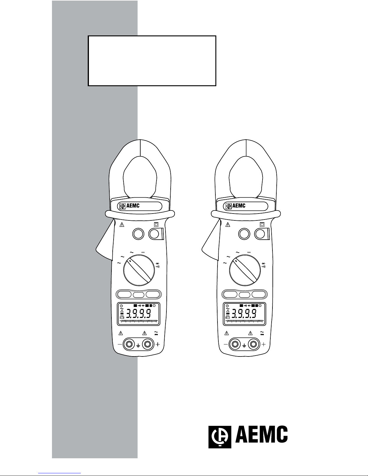
Clamp-on Meter Models 511 and 512
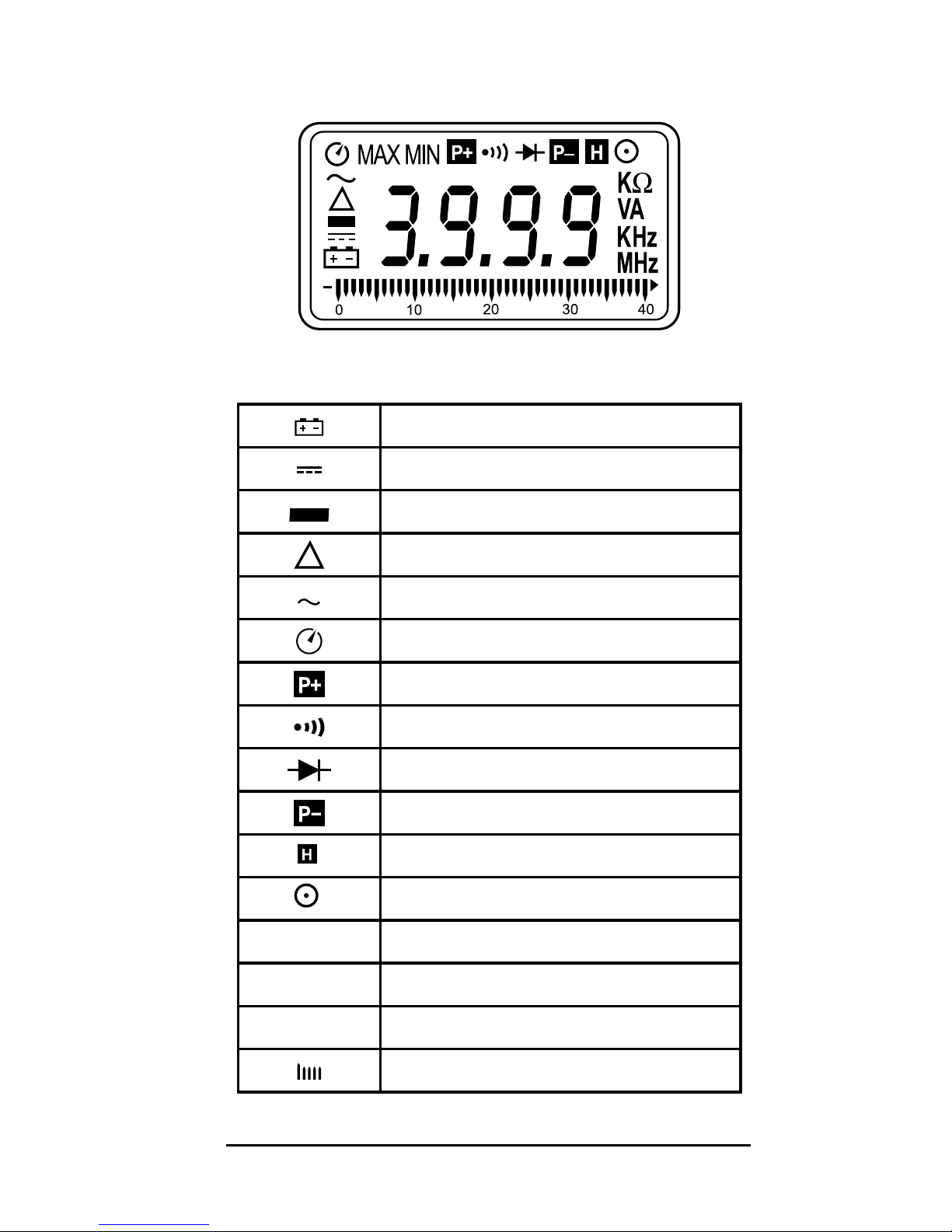
1.1 International Electrical Symbols
This symbol signies that the instrument is pro-
tected by double or reinforced insulation.
This symbol on the instrument indicates a
WARNING and that the operator must refer to the
user manual for instructions before operating the
instrument. In this manual, the symbol preceding
instructions indicates that if the instructions are
not followed, bodily injury, installation/sample and
product damage may result.
Risk of electric shock. The voltage at the parts
marked with this symbol may be dangerous.
1.2 Receiving Your Shipment
Uponreceiving your shipment, makesurethat the con-
tents are consistent with the packing list. Notify your dis-
tributor of any missing items. If the equipment appears to
bedamaged,leaclaimimmediatelywiththecarrierand
notify your distributor at once, giving a detailed descrip-
tion of any damage. Save the damaged packing container
to substantiate your claim.
1.3 Ordering Information
Clamp-on Meter Model 511 .....................Cat. #2117.67
Includes meter, pair of test leads (red/black with probe tips), one
9V battery, soft carrying case and a user manual.
TRMS Clamp-on Meter Model 512..........Cat. #2117.68
Includes meter, pair of test leads (red/black with probe tips), one
9V battery, soft carrying case and a user manual.
1.3.1 Accessories and Replacement Parts
Set of 2, 5 ft color-coded leads..................Cat. #2140.68
Replacement Pouch ..................................Cat. #2118.94
www.ShopAEMC.com
Shop for AEMC products online at: 1.888.610.7664