Aercus WeatherMaster User manual

WeatherMaster
MULTI-CHANNEL WIFI
WEATHER STATION WITH
INTERNET PUBLISHING

Aercus Instruments™
-
WeatherMaster
2
|
P a g e
WeatherMaster
MULTI-CHANNEL WIRELESS
WEATHER STATION WITH INTERNET PUBLISHING
Mode d'emp oi en français
Téléchargez ce manuel d'instructions en français sur
aercusinstruments.com/manuals/
Manua e Operativo in ita iano
Scarica uesto manuale di istruzioni in italiano da
aercusinstruments.com/manuals/
Operation Manua
About This Manua
Thank you and congratulations on selecting this professional weather
station. We are positive you will enjoy the benefits of accurate weather
readings and information that our weather stations offer. This manual
will guide you step-by-step through setting up your device. Use this manual
to become familiar with your professional weather station and save it for
future reference.
For optimal performance from your Aercus Instruments WeatherMaster
we strongly recommend you read this manual thoroughly before
beginning installation. Installation is simple if the steps below are
followed and doing so will ensure that you avoid the most common
pitfalls of weather station operation.

Aercus Instruments™
-
WeatherMaster
3
|
P a g e
Important!
Warranty and Support
We warrant our products to be free of defects in components and
workmanship, under normal use and service, for one year from the date of
original purchase. For product support and warranty claims please contact
the following:
Purchased in UK/EU: As many issues can be a result of incorrect
setup please contact our local distributor Greenfrog Scientific
greenfrogscientific.co.uk and their team will be happy to help.
Genuine faults can typically be diagnosed without re uiring the
unit to be returned and replacement parts sent uickly if needed.
Purchased in AUSTRALIA: As many issues can be a result of
incorrect setup please contact our local distributor Monax Test &
Weather monaxtestandweather.com.au and their team will be
happy to help. Genuine faults can typically be diagnosed without
re uiring the unit to be returned and replacement parts sent
uickly if needed.
Purchased in NEW ZEALAND: As many issues can be a result of
incorrect setup please contact our local distributor Scientific Sales
scientificsales.co.nz and their team will be happy to help.
Genuine faults can typically be diagnosed without re uiring the
unit to be returned and replacement parts sent uickly if needed.
For all others, please contact the seller who sold you this item.

Aercus Instruments™
-
WeatherMaster
4
|
P a g e
Contents
1.
Pre-Insta ation Check and Site Survey ............................................................... 6
1.1 Pre-installation Check ...................................................................................... 6
1.2 Site Survey ....................................................................................................... 7
2.
Unpacking .......................................................................................................... 8
3.
Disp ay conso e .................................................................................................. 9
3.1 Optional sensors ............................................................................................ 11
4.
Set up Guide .................................................................................................... 13
4.1 Pre-installation .............................................................................................. 13
4.2 Outdoor Sensor Package Assembly ............................................................... 13
4.2.1 Install U-bolts and metal plate ............................................................... 13
4.2.2 Install wind vane .................................................................................... 14
4.2.3 Install anemometer ................................................................................ 15
4.2.4 Install rain gauge funnel ......................................................................... 16
4.2.5 Install Batteries in sensor pac age ......................................................... 16
4.2.6 Mount assembled outdoor sensor pac age ........................................... 18
4.2.7 Reset Button and Transmitter LED ......................................................... 19
4.3 Indoor Sensor Set Up ..................................................................................... 19
4.4 Multi-channel temperature and humidity sensor (Optional) ........................ 20
4.4.1 Install batteries ....................................................................................... 21
4.4.2 Sensor Placement ................................................................................... 23
4.5 Best Practices for Wireless Communication .................................................. 24
4.6 Console Setup ................................................................................................ 26
4.6.1 Initial Display Console Set Up ................................................................. 28
4.6.2 Key functions .......................................................................................... 30
4.6.3 Main interface icons ............................................................................... 31
4.7 Multiple Channel Selection and Scroll Mode ................................................ 33
4.8 History Mode ................................................................................................. 34
4.8.1 View and Reset MAX/MIN ...................................................................... 34

Aercus Instruments™
-
WeatherMaster
5
|
P a g e
4.8.2 History Record Mode .............................................................................. 35
4.8.3 View Graph ............................................................................................. 38
4.8.4 View Channel Data ................................................................................. 39
4.9 Setup Mode ................................................................................................... 40
4.9.1 Date and Time setup .............................................................................. 42
4.9.2 Time format setup .................................................................................. 44
4.9.3 Date format setup .................................................................................. 44
4.9.4 Temperature unit setup .......................................................................... 44
4.9.5 Barometric pressure unit setup .............................................................. 44
4.9.6 Wind speed unit setup ............................................................................ 44
4.9.7 Rainfall unit setup .................................................................................. 44
4.9.8 Solar radiation unit setup ....................................................................... 45
4.9.9 Multi-channel sensor setup .................................................................... 45
4.9.10 Bac light setting ................................................................................... 46
4.9.11 Longitude and Latitude setup ............................................................... 48
4.9.12 Barometric display setting.................................................................... 49
4.9.13 Rainfall season (default: January) ........................................................ 49
4.9.14 Storing interval setup ........................................................................... 49
4.9.15 Weather Server..................................................................................... 49
4.9.16 Wunderground server setup ................................................................. 51
4.9.17 Weathercloud server setup .................................................................. 55
4.9.18 Wi-Fi scan ............................................................................................. 64
4.9.19 Bac ground .......................................................................................... 66
4.9.20 More ..................................................................................................... 66
4.10 Alarm Setup Mode ....................................................................................... 71
4.11 Calibration Mode ......................................................................................... 73
4.12 Factory reset ................................................................................................ 78
4.12.1 Re-register indoor transmitter ............................................................. 78
4.12.2 Re-register outdoor transmitter ........................................................... 79
4.12.3 Automatic Clear Max/Min .................................................................... 79
4.12.4 Reset to Factory .................................................................................... 79
4.12.5 Clear History ......................................................................................... 79

Aercus Instruments™
-
WeatherMaster
6
|
P a g e
4.12.6 Clear Max/Min ..................................................................................... 80
4.12.7 Bac up data ......................................................................................... 80
4.12.8 About information ................................................................................ 81
4.12.9 Language .............................................................................................. 81
5.
Other Conso e Functions .................................................................................. 82
5.1 Beaufort Wind Force Scale ............................................................................ 82
5.2 Weather Forecasting ..................................................................................... 83
5.3 Lightning Alert ............................................................................................... 83
5.4 Weather Forecasting Description and Limitations ........................................ 84
5.5 Moon Phase ................................................................................................... 84
6.
Maintenance ................................................................................................... 86
7.
Troub eshooting Guide .................................................................................... 87
8.
G ossary of Common Terms ............................................................................. 91
9.
Specifications .................................................................................................. 94
10.
Contact Information ...................................................................................... 96
1.
Pre-Installation Check and Site Survey
1.1 Pre-insta ation Check
Before installing your weather station in its permanent location, we
recommend operating the weather station for one week in a temporary
location with easy access. This will allow you to check out all the
functions, ensure proper operation, and familiarise yourself with the
weather station and calibration procedures. This will also allow you to
test the wireless range of the weather station.

Aercus Instruments™
-
WeatherMaster
7
|
P a g e
1.2 Site Survey
Perform a site survey before installing the weather station. Consider the
following:
1.
You must clean the rain gauge every few months and change
the batteries every 12 months or so. Ensure you have easy
access to the weather station.
2.
Avoid radiant heat transfer from buildings and structures. In
general, install the sensor array at least 1.5m from any building,
structure, ground, or roof top.
3.
Avoid wind and rain obstructions. The rule of thumb is to
install the sensor array at least four times the distance of the
height of the tallest obstruction. For example, if the building
is 6m tall, and the mounting pole is 2m tall, install 4 x (8m –
2m) = 24m away.
4.
Wireless Range. The radio communication between receiver
and transmitter in an open field can reach up to 100m,
providing there are no interfering obstacles such as buildings,
trees, vehicles, high voltage lines. Wireless signals will not
penetrate metal buildings. Under most conditions, the
maximum wireless range is 20-40m.
5.
Radio interference such as PCs, radios or TV sets can, in the
worst case, entirely cut off radio communication. Please take
this into consideration when choosing console or mounting
locations. Make sure your display console is at least 1.5m away
from any electronic device to avoid interference.

Aercus Instruments™
-
WeatherMaster
8
|
P a g e
2.
Unpacking
Open your weather station box and inspect that the contents are intact
(nothing broken) and complete (nothing missing). Inside you should find
the following:
QTY
Item Description
1
Display console
1
AC adapter
1
Outdoor sensor
array with the following sensors:
temperature/humidity, rain gauge, wind speed, wind direction,
light and UV and solar panel
1
Wind speed cups (to be attached to outdoor sensor body)
1
Wind vane (to be attached to outdoor sensor body)
1
Indoor
sensor unit
2
U
-
bolts for mounting on a pole
4
Threaded nuts for U
-
bolts (M5 size)
1
Metal mounting plate to be used with U
-
bolts
1
Wrench for M5 bolts
1
User manual (this manual)
Tab e: Box contents
If components are missing from the package, or broken, please contact
your local distributor to resolve the issue.
Note: Batteries for the outdoor sensor package are not inc uded. You will
need 2 AA-sized batteries, alkaline or Lithium batteries (Lithium is
recommended for colder climates).
Note: The console operates using an AC adapter. The included adapter
can generate a small amount of electrical interference with the RF
reception in the console, when placed too close to the console.
Please keep the console display 50cm/2ft from the power adapter
to ensure best RF reception.

Aercus Instruments™
-
WeatherMaster
9
|
P a g e
3.
Display console
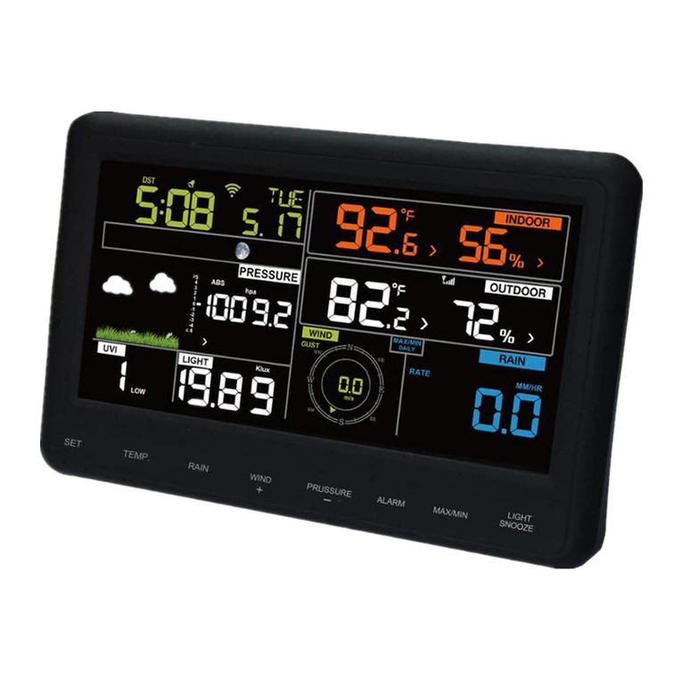
Figure 1: Disp ay conso e
Note: The USB port in the console of weather station is only for firmware
updates, not for data communication and a USB cable is not included. An
SD card (not included ) can also be used for the firmware update.
USB port
R
eset
Power jack
memory card slot

Aercus Instruments™
-
WeatherMaster
10
|
P a g e
Outdoor sensor:
Figure 3: Sensor assemb y components
1 Wind vane 7 Solar panel
2 Wind speed cups 8 U-Bolts
3 Light sensor and UV sensor 9 Battery compartment
4 Thermo/hygrometer sensor 10 Reset button
5 Rain collector 11 LED (red)
6 Bubble level
Indoor sensor:
Figure 2: Indoor sensor 2 disp ay variations
The indoor sensor will display indoor temperature, humidity, and
barometric pressure alternately.

Aercus Instruments™
-
WeatherMaster
11
|
P a g e
3.1 Optiona sensors
The following optional sensors (purchased separately) can be used with the
WeatherMaster.
If you have purchased extra sensors, just simple power up, the display
console will receives the data automatically. If sensor not reporting in to
console, the display console will re-search the data after one hour or
restart the console to search the data. Please refer to the sensor manual
(provided separately with sensor) for details.
This table shows the maximum number of each type of sensor that can be
worked with console display
Sensor Image Maximum
WH31 Multi-channel temperature and
humidity sensor
8
WH51 Soil moisture sensor
8
WH41 outdoor PM2.5 air uality sensor
WH43 indoor PM2.5 air uality sensor
WH41 and WH43 share the four channels
4
WH55 Water leak alarm
4

Aercus Instruments™
-
WeatherMaster
12
|
P a g e
WH57 Lightning
1
WH45 Indoor PM2.5/PM10 CO
2
air uality
sensor
1
WN34S stainless-steel probe thermometer
for soil and water
WN34L wire probe thermometer for water
WN34S and WN34L share the 8 channels
8
WN35 leaf wetness sensor - data will not
be displayed on the main screen, it will
show its data on the
Channel Data page.
8
Note:For optional sensors, the console will display current data, and
historical data is saved on an SD card. If you are uploading to the internet,
some websites do not support additional sensor data. We recommend
Ecowitt.net.

Aercus Instruments™
-
WeatherMaster
13
|
P a g e
4.
Set up Guide
4.1 Pre-insta ation
To complete assembly you will need a Philips screwdriver (size PH0) and an
M5 wrench (included).
For setup we recommend placing the weather station in a temporary
location with easy access for one week. This will let you check all functions,
ensure proper operation, and get familiar with the weather station and its
calibration procedures.
Attention:
Ensure batteries are installed with correct polarity (+/-)
Do not mix old and new batteries
Do not use rechargeable batteries
If outdoor temperature go below 0°C for prolonged periods, Lithium
based batteries are recommended for optimal performance
4.2 Outdoor Sensor Package Assemb y
4.2.1 Insta U-bo ts and meta p ate
Installation of the U-bolts, which are in turn used to mount the sensor
package on a pole, re uires installation of an included metal plate to
receive the U-bolt ends. The metal plate, has four holes through which the
ends of the two U-bolts will fit. The plate itself is inserted in a groove on the
bottom of the unit (opposite the solar panel). Note that one side of the
plate has a straight edge (which goes into the groove), the other side is
bent at a 90-degree angle and has a curved profile (which will end up
“hugging” the mounting pole). Once the metal plate is inserted, insert both
U-bolts through the respective holes of the metal plate as shown in Figure
4.

Aercus Instruments™
-
WeatherMaster
14
|
P a g e
Figure 4: U-Bo t insta ation
The plate and U-bolts are not yet needed at this stage but doing this now
may help avoid damaging wind vane and wind speed cups later. Handling of
the sensor package with wind vane and anemometer installed to install
these bolts is more difficult and more likely to lead to damage.
4.2.2 Insta wind vane
Push the wind vane onto the shaft on the opposite side of the wind cups,
until it goes no further, as shown on the left side in Figure 6. Next, tighten
the set screw, with a Philips screwdriver (size PH0), as shown on the right
side, until the wind vane cannot be removed from the axle. Make sure the
wind vane can rotate freely. The wind vane’s movement has a small
amount of friction, which is helpful in providing steady wind direction
measurements
Figure 5: Wind vane insta ation diagram

Aercus Instruments™
-
WeatherMaster
15
|
P a g e
The sensor array must be oriented so that the arrow marked “North” on
the top of the wireless sensor is pointing north. If the sensor array is
oriented incorrectly, wind direction measurement will be inaccurate.
4.2.3 Insta anemometer
Push the anemometer assembly onto the shaft on the top side of the
sensor package, as shown in Figure 6 (left). Tighten the set screw, with a
Philips screwdriver (size PH0), as shown on the right. Make sure the cup
assembly can rotate freely. There should be no noticeable friction when it is
turning.
Figure 6: Wind speed cup insta ation diagram

Aercus Instruments™
-
WeatherMaster
16
|
P a g e
4.2.4 Insta rain gauge funne
Turn clockwise to attach the funnel to the sensor array.
Figure 7: Rain Gauge Funne insta ation diagram
4.2.5 Insta Batteries in sensor package
Insert 2xAA batteries into the battery compartment and tighten the screw
of battery cover. The LED indicator on the back of the transmitter will turn
on for 4 seconds and flash once every 16 seconds.
Figure 8: Battery insta ation diagram

Aercus Instruments™
-
WeatherMaster
17
|
P a g e
Note: If no LED lights up or is illuminated permanently, make sure the
battery is inserted the correct way and that a proper reset has been
performed. Do not install the batteries backwards. You can
permanently damage the outdoor sensor.
Note: The LED can be hard to see in bright light.
Note: We recommend lithium batteries for cold weather climates, but
alkaline batteries are sufficient for most climates. We do not
recommend rechargeable batteries. They have lower voltages, do
not operate well at wide temperature ranges and do not last as
long, resulting in poorer reception.

Aercus Instruments™
-
WeatherMaster
18
|
P a g e
4.2.6 Mount assemb ed outdoor sensor package
Install the sensor array in an open space, away from obstacles such as other
buildings, trees, etc. that prevent free wind flow, to ensure undistorted
measurements of individual weather elements. Point the part with the
vane and propeller north for correct wind direction measurement. Place
the sensor array onto the stand (not included) at a minimum height of 1.5
metres from the ground to prevent the measured values being affected by
the ground surface and tighten the bolts. Use the spirit level on the top of
the sensor array to ensure that it is level. Tighten the U-bolt nuts.
Figure 9: Sensor package mounting diagram
Note: If you handle the sensor array when it is powered up and
transmitting, you can generate false wind reading as you move
and rain readings if to tip the array. Please remember to reset
your readings.

Aercus Instruments™
-
WeatherMaster
19
|
P a g e
4.2.7 Reset Button and Transmitter LED
In the event the sensor array is not transmitting, reset the sensor array.
Using a skewer or open paperclip, press and hold the Reset Button (see
Figure 0) to affect a reset. The LED turns on while the Reset button is
depressed, and it can now be released. The LED should then return to
flashing approximately once every 16 seconds.
Figure 10: Reset button and Transmitter LED ocation
4.3 Indoor Sensor Set Up
Note: To avoid permanent damage, please take note of the battery polarity
before inserting the batteries.
Remove the battery door on the back of the sensor. Insert two AA batteries
(See Figure 11)

Aercus Instruments™
-
WeatherMaster
20
|
P a g e
Figure 11: Indoor sensor battery insta ation
4.4 Mu ti-channe temperature and humidity sensor (Optiona )
The WeatherMaster supports up to 8 additional thermo-hygrometer
sensors (WH31), which can be viewed on the display tablet and Internet.
Note: Do not use rechargeable batteries. We recommend fresh alkaline
batteries for outdoor temperature ranges between -10°C and 60°C and
fresh lithium batteries for outdoor temperature ranges between -40°C and
-10°C.
Table of contents
Other Aercus Weather Station manuals
Aercus
Aercus WS2073 User manual
Aercus
Aercus WS3083 User manual
Aercus
Aercus WS3085 User manual
Aercus
Aercus WS2083 User manual

Aercus
Aercus WS1093 User manual
Aercus
Aercus WS2085 User manual
Aercus
Aercus WH41 User manual
Aercus
Aercus WS1173 User manual
Aercus
Aercus WeatherSpy User manual
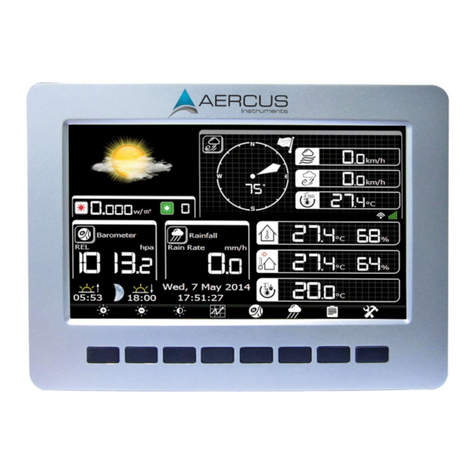
Aercus
Aercus WeatherRanger User manual
Popular Weather Station manuals by other brands

elsner elektronik
elsner elektronik Suntracer KNX sl basic Technical specifications and installation instructions

Oregon Scientific
Oregon Scientific WMR300 user manual

La Crosse Technology
La Crosse Technology WS6828 Quick setup guide

General
General WS831DL user manual

Explore Scientific
Explore Scientific WSX1001 instruction manual
Silva
Silva ADC Wind quick guide


