Aereco DXR Quick start guide

INSTALLATION AND USE (EN)
MONTAGE UND VERWENDUNG (DE)
INSTALLATION ET UTILISATION (FR)
Fonctions principales :
• Démarrage du système
• Surventilation et rafraîchissement
• Paramètres du système
• Fonctionnement et performances
• Maintenance
Hauptfunktionen:
• Systemstart
• Intensivlüftung und Kühlung
• Systemparameter
• Betriebs- und Leistungsdaten
• Wartung
Main functions:
• Starting the system
• Boost ventilation and free cooling
• System settings
• Operating and performance
• Maintenance
XP-1 (Bedarfsgeführte Wohnungslüftung mit Wärmerückgewinnung) Grafik-Display
DXR (Room-by-room demand control heat recovery) Graphic interface
DXR (double flux modulé avec récupération de chaleur) Interface graphique
TF5822_B
06/10/2015

2 / 52
TF5822_B
DE
1. Einführung 4
2. Piktogramme Präsentation der raumweisen bedarfsgeführten
Wohnungslüftung XP-1 4
3. Piktogramme 6
4. Allgemeiner Betrieb 8
4.1. Hauptmenü 8
4.2. Aufbau des Bildschirms und Navigation zwischen den
verschiedenen Menüs 8
4.3. Standby 10
5. Initialisierung 10
5.1. Grafik-Display Anschließen 10
5.2. Sprachwahl 10
5.3. Montagedatum 12
5.4. Vorerhitzer 12
5.5. Temperatureinheit wählen 12
5.6. Kondensatpumpe 14
5.7. Anzahl der angeschlossenen Sensoren bestimmen 14
5.8. Zuordnung der Sensoren und Zuluftelemente 16
5.9. Filtertests 18
6. Benutzermenü 20
6.1. Intensivlüftung 20
6.1.1 Einschalten der Intensivlüftung 20
6.1.2 Parametrieren der Intensivlüftung 20
6.1.3 Anhalten der Intensivlüftung 22
6.2. Kühlung 22
6.2.1 Inbetriebnahme der Kühlung 22
6.2.2 Parametrieren der Kühlung 22
6.2.3 Anhalten der Kühlung 24
6.3. BYPASS 26
6.3.1 Einstellen des BYPASS 26
6.4. Statistische Betriebsdaten 30
6.4.1 Luftmenge, Druck, Zulufttemperatur 30
6.4.2 Öffnung der Zuluftstellventile 30
6.4.3 Vorheizregister 32
6.5. Energieeffizienz 34
6.5.1 Energierückgewinnung 34
6.5.2 Heizenergieeinsparung 34
6.6. Zusätzliche Parameter 36
6.6.1 Sprachwahl 36
6.6.2 Temperatureinheit wählen 36
6.7. Filter und Filterwechsel 36
6.7.1 Letzter Filtertest 36
6.7.2 Verschmutzungsgrad der Filter 38
6.7.3 Filtertest laufen lassen 38
7. Alarme 40
7.1. Filtertest-Alarm 40
7.2. Filter-Alarm 40
7.3. Sensor-Alarm 42
7.4. Vorheizregister-Alarm 42
7.5. Kondensatpumpen-Alarm 42
8. Display außer Spannung setzen und rückstellen 44
8.1. Display außer Spannung setzen 44
8.2. Display rückstellen 44
9. Fehlerbehebung 46
10. Garantie - Kundendienst - Konformität 49

3 / 52
TF5822_B
FREN
1. Introduction 5
2. Presentation of the room by room demand control
heat recovery 5
3. Pictograms 7
4. General operation 9
4.1. Main menu 9
4.2. Organization of the screen and navigation between
the menus 9
4.3. Standby 11
5. Initialization 11
5.1. Connecting the graphic interface 11
5.2. Choice of language 11
5.3. Date of installation 13
5.4. Defrosting device 13
5.5. Choice of unit of temperature 13
5.6. Condensation pump 15
5.7. Determination of the number of sensors connected 15
5.8. Pairing of sensors and supply units 17
5.9. Test of the filters 19
6. User menu 21
6.1. Boost ventilation 21
6.1.1 Starting the boost ventilation function 21
6.1.2 Parameterizing boost ventilation 21
6.1.3 Stopping boost ventilation 23
6.2. Free cooling 23
6.2.1 Starting free cooling 23
6.2.2 Parameterizing free cooling 23
6.2.3 Stopping free cooling 25
6.3. BYPASS 27
6.3.1 Parameterizing the BYPASS function 27
6.4. Operating statistics 31
6.4.1 Supply air flow, pressure, and temperature 31
6.4.2 Opening of the supply units 31
6.4.3 Defrosting device 33
6.5. Energy performance 35
6.5.1 Heat recovery 35
6.5.2 Heating savings 35
6.6. Additional settings 37
6.6.1 Choice of language 37
6.6.2 Choice of unit of temperature 37
6.7. Filters and Maintenance 37
6.7.1 Last filters test 37
6.7.2 Filters clogging 39
6.7.3 Starting the filter test 39
7. Alarms 41
7.1. Filter test alarm 41
7.2. Filter alert 41
7.3. Sensor alert 43
7.4. Defrosting alert 43
7.5. Condensation pump alert 43
8. Powering down and reset of the interface 45
8.1. Powering down the interface 45
8.2. Resetting the interface 45
9. Troubleshooting 47
10. Warranty-Customer service-Conformity 50
1. Introduction 5
2. Présentation du double flux modulé pièce 5
3. Pictogrammes 7
4. Fonctionnement général 9
4.1. Menu principal 9
4.2.Organisation de l’écran et navigation entre les menus 9
4.3. Mise en veille 11
5. Initialisation 11
5.1. Branchement de l’interface graphique 11
5.2. Choix de la langue 11
5.3. Date d’installation 13
5.4. Dispositif de dégivrage 13
5.5. Choix de l’unité de température 13
5.6. Pompe à condensats 15
5.7. Détermination du nombre de capteurs connectés 15
5.8. Association capteurs - bouches de souage 17
5.9. Test filtres 19
6. Menu utilisateur 21
6.1. Surventilation 21
6.1.1 Mise en route de la surventilation 21
6.1.2 Parametrage de la surventilation 21
6.1.3 Arrêt de la surventilation 23
6.2. Rafraîchissement 23
6.2.1 Mise en route du rafraîchissement 23
6.2.2 Paramétrage du rafraîchissement 23
6.2.3 Arrêt du rafraîchissement 25
6.3. BYPASS 27
6.3.1 Paramétrage du BYPASS 27
6.4. Statistiques de fonctionnement 31
6.4.1 Débit d’air, pression, température au soufflage 31
6.4.2 Ouverture des bouches de soufflage 31
6.4.3 Dispositif de dégivrage 33
6.5. Performance énergétique 35
6.5.1 Récupération d’énergie 35
6.5.2 Économies de chauffage 35
6.6. Paramètres supplémentaires 37
6.6.1 Choix de la langue 37
6.6.2 Choix de l’unité de température 37
6.7. Filtres et Maintenance 37
6.7.1 Dernier test filtre 37
6.7.2 Taux d’encrassement des filtres 39
6.7.3 Lancement du test filtre 39
7. Alarmes 41
7.1. Alarme test filtres 41
7.2. Alerte filtres 41
7.3. Alerte capteurs 43
7.4. Alerte dégivrage 43
7.5. Alerte pompe à condensats 43
8. Mise hors tension et réinitialisation de l’interface 45
8.1. Mise hors tension de l’interface 45
8.2. Réinitialisation de l’interface 45
9. Résolution des problèmes 48
10. Garantie – SAV – Conformité 51

4 / 52
TF5822_B
DE
1. EINFÜHRUNG
Herzlichen Glückwunsch, Sie haben sich für eine raumweise bedarfsgeführte Zu- und Abluftanlage XP-1 von Aereco entschieden. Mit Hilfe
dieser Anlage gewährleisten Sie eine ständige optimale Innenraumluftqualität und sparen dabei noch an Energiekosten.
Bitte lesen Sie diese Gebrauchsanweisung aufmerksam durch.
2. PRÄSENTATION DER RAUMWEISEN BEDARFSGEFÜHRTEN WOHNUNGSLÜFTUNG XP-1
Beim Nutzen einer Wohnung werden permanent Feuchte und CO2abgegeben, durch unterschiedliche Tätigkeiten und Nutzung der Räume. In der Küche
wird z.B. gekocht, im Bad geduscht oder Wäsche getrocknet usw. Durch das Atmen wird ebenfalls Feuchte produziert. Die verwendeten Baumaterialien in
den Wohnräumen geben Schadstoe ab z.B. Farben, Kleber, Bodenbeläge etc. Ohne ein Abführen dieser Schadstoe mit Hilfe einer Lüftung sammeln sich
diese Schadstoe in gut gedämmten Wohnungen an und können sowohl die Gesundheit als auch die Wohnung belasten.
Die Zu- und Abluftanlage ist ein Lüftungssystem, das die verbrauchte Luft aus den Ablufträumen wie Küche, Bad, WC, Waschraum usw. abzieht, filtert und
gleichzeitig gefilterte Aussenluft vorgewärmt als Zuluft in den Wohn- und Schlafräumen verteilt.
Die Zu- und Abluftanlage XP-1:
Siehe Bild 1 : Lüftungssystem mit raumweiser bedarfsgeführter Zu- und Abluftanlage XP-1und XP-1 Hub.
Siehe Bild 2
Das XP-1-System besteht aus dem zentralen Gerät mit Wärmerückgewinnung (XP-1: A), die an die Abluftelemente (B)und eine Luftverteilungsbox
angeschlossen ist (XP-1 Hub: C) welche die Zuluftmengen in Abhängigkeit des CO2 Wertes moduliert (D).
Der eingebaute Gegenstromwärmeübertrager führt einen Großteil der Wärme aus der Abluft der kalten Aussenluft zu und spart damit für die
Luftvorerwärmung erforderliche Energie.
A
B
B
E
D
C
2

5 / 52
FREN
TF5822_B
1. INTRODUCTION
Vous venez d’acquérir le DXR d’Aereco : un système double flux
à débits modulés pièce par pièce. Ce système va vous permettre
d’assurer en permanence une bonne qualité d’air à l’intérieur
de votre logement tout en vous faisant réaliser des économies
d’énergie.
Nous vous invitons à lire attentivement cette notice d’utilisation avant
toute manipulation de votre produit.
2. PRÉSENTATION DU DOUBLE FLUX MODULÉ
PIÈCE PAR PIÈCE DXR
Que ce soit par son activité (cuisine, douche, séchage de linge, etc.)
ou par son métabolisme (respiration et transpiration), l’occupant émet
à tout moment de l’humidité et du CO2. Le logement est lui-même
source de polluants (peintures, revêtements de sols…). Sans ventilation
correctement conçue et dans un logement assez étanche, les polluants
s’accumulent et peuvent avoir des eets néfastes sur votre santé et
votre logement.
La VMC Double Flux est un système de ventilation qui assure la filtration
et l’extraction de l’air vicié des pièces de services (cuisine, salle de bains,
WC, buanderie…) et qui simultanément, assure l’insuation de l’air neuf
filtré dans les pièces de vie (séjour, chambre, bureau…).
Le double flux DXR :
Figure 1: Système de ventilation double flux à débit modulé pièce par
pièce. DXR Unit et DXR Hub.
Voir figure 2
Le système DXR est constitué d’un double flux avec récupérateur de
chaleur (DXR Unit : A) raccordé à des bouches d’extraction (B) et à une
boîte de répartition (DXR Hub : C) modulant les débits d’air insués en
fonction du CO2(D).
L’échangeur thermique à contre-courant intégré au double flux assure
la récupération d’une grande partie de la chaleur de l’air extrait vers l’air
entrant pour limiter l’énergie nécessaire à son réchauage.
1. INTRODUCTION
You are the new owner of an Aereco DXR: a heat-recovery with
room-by-room demand control airflow rate. This system will ensure
good air quality in your dwelling at all times while helping you to
save energy.
Please read this user manual carefully before any handling of your
product.
2. PRESENTATION OF THE ROOM BY ROOM
DEMAND CONTROL HEAT RECOVERY
Whatever they may be doing (cooking, showering, drying clothes, etc.)
and whatever their metabolism (breathing, transpiration), the occupants
of a dwelling give o moisture and CO2at all times. The dwelling is itself
a source of pollution (paint, floor coverings, etc.). In a dwelling that is
reasonably air-tight, pollutants accumulate and may have harmful eects
on your health and on your dwelling, unless there is a well-designed
ventilation system.
The heat recovery ventilation is a ventilation system that filters and
exhausts stale air from wet rooms (kitchen, bathroom, WC, laundry room,
etc.) and supplies filtered fresh air to living areas (living room, bedrooms,
oce, etc.).
DXR heat recovery:
Figure 1: Heat recovery ventilation system with room-by-room
controlled airflow rate. DXR Unit and DXR Hub.
See figure 2
The DXR system is a heat recovery system with a heat exchanger (DXR
Unit: A) connected to exhaust units (B) and to a distribution box (DXR
Hub: C) that modulates the supply air flow rates as a function of CO2(D).
The supply air recovers a large fraction of the heat from the exhaust air in
the counter-current exchanger built into the heat recovery system, limiting
the energy needed to heat it.
1

6 / 52
DE
TF5822_B
A
B
C
Alle Luftmengen werden in Abhängigkeit des Lüftungsbedarfs in
jedem Raum der Wohnung automatisch angepasst: Zuluft in den
Wohn- und Schlafräumen, Abluft in der Küche, Bad und WC. Die
einzelnen Zuluftelemente sind direkt an die Luftverteilungsbox XP-1
Hub angeschlossen. Die Luftverteilbox passt in jedem Wohn- und
Schlafraum unter Einbeziehung der dort gemessenen, relativen
CO2-Konzentration (E) die Zuluftmenge an. Abluftseitig passen die
Abluftelemente die Luftmenge anhand verschiedener Parameter für eine
bedarfsgerechte Lüftung in den Ablufträumen an: Feuchtigkeit im Bad
(AH 80), Anwesenheit im WC (ASOGZ 80), Feuchtigkeit mit Taster für
Intensivlüftung (AHSIN 80) in der Küche. Außerdem sind Versionen mit
CO2- bzw. VOC-Messung auch an der Abluftseite möglich.
Die gesamte Zu- und Abluftmenge wird laufend gemessen und
mit Hilfe von zwei gesteuerten Kompensationsventilen erfolgt
in einem Wohnraum, Küche oder in einem Flur/Korridor die
Luftmengenbalancierung, um die Volumenströme im Gleichgewicht zu
halten. Wenn der Bedarf also z.B. beim Kochen in der Küche aufgrund
relativer Feuchte ansteigt, in Wohn- und Schlafräumen jedoch kein
Bedarf besteht die Luftmenge auf der Zuluftseite zu erhöhen, lässt
sich die angeforderte Abluftmenge, durch Önen der im XP-1 Hub
liegenden Kompensation des Zuluftsystems gewährleisten, sodass die
Volumenströme ausgeglichen sind.
Ein im zentralen Gerät befindlicher Bypass sorgt dafür, dass im Sommer
der Wärmeübertrager nicht mit warmer Aussenluft beaufschlagt wird,
um so ggf. auch eine free-cooling Funktion für eine Nachtauskühlung im
Rahmen der technischen Möglichkeitenzu gewährleisten.
Grafik-Display:
Siehe Bild 3: Touchpad-Display für Anzeige, Einstellung und
Auswertung des XP-1.
Ein farbiges LCD-Touchpad-Display zeigt die jeweiligen
Leistungsparameter (Luftmenge, Stromaufnahme etc.) und den
einwandfreien Betrieb der Gerätemodule an und ermöglicht es,
unterschiedliche Parameter einzustellen (Temperatur für den
automatischen Bypass, Wohnraumkühlung mit free-cooling nach
Bedarf).
Der Bewohner erhält auch eine Information sobald die Filter
ausgetauscht werden müssen.
3. PIKTOGRAMME
AWichtiger Hinweis. Gefahr einer Beschädigung des Geräts bzw.
Beeinträchtigung der Ezienz und Lebensdauer des Geräts.
BLange Initialisierungsdauer (>10 Minuten).
CGefahr einer Lärmbelästigung.
3

7 / 52
FREN
TF5822_B
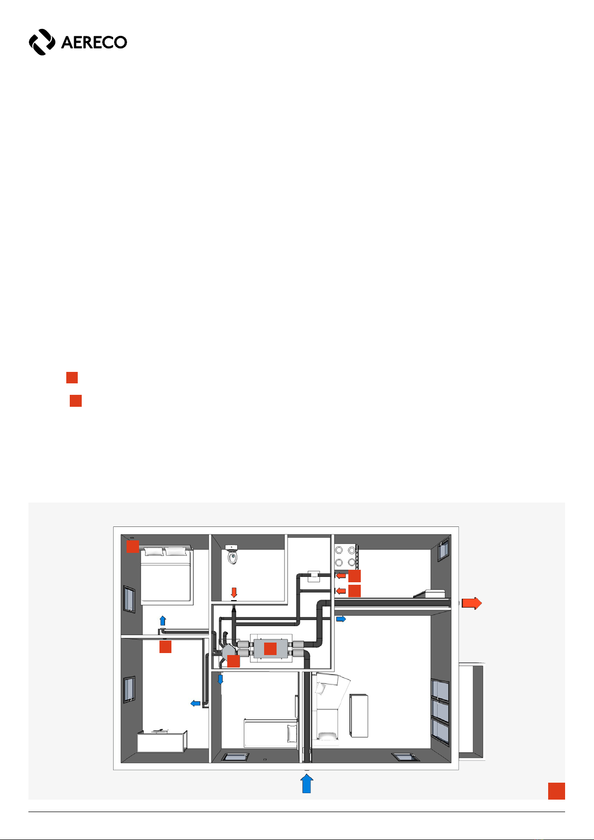
The air flow rates are automatically modulated according to the needs
of each room of the dwelling: both the air supplied to the bedrooms and
living room and the air exhausted from the kitchen, bathroom, and WC.
Each supply unit is directly connected to the DXR Hub (distribution box),
which adjusts the flow of air to each main room according to the level
of CO2(E), in proportion to the measured level. On the exhaust side,
the BXC units adjust the air flows according to parameters that dier
between the rooms: humidity in the bathroom, presence in the toilets,
humidity and boost flow rate control pushbutton in the kitchen. Versions
with CO2or VOC detection can also be used for the exhaust function.
The total supply and exhaust air flow rates are measured by the heat
recovery system at all times and balanced by means of two controlled
compensation valves, which can be placed in the living room, the
kitchen, or a corridor. And when, for example, the need increases in the
kitchen during the preparation of a meal, without there being a matching
high demand in a bedroom or the living room, the exhaust flow rate
required can be provided by opening the compensation valve (in the DXR
Hub) of the supply network.
The bypass in the heat recovery system automatically shunts the
exchanger when the outdoor temperature is warm enough; it can also be
actuated in the free-cooling mode for cooling at night in summer.
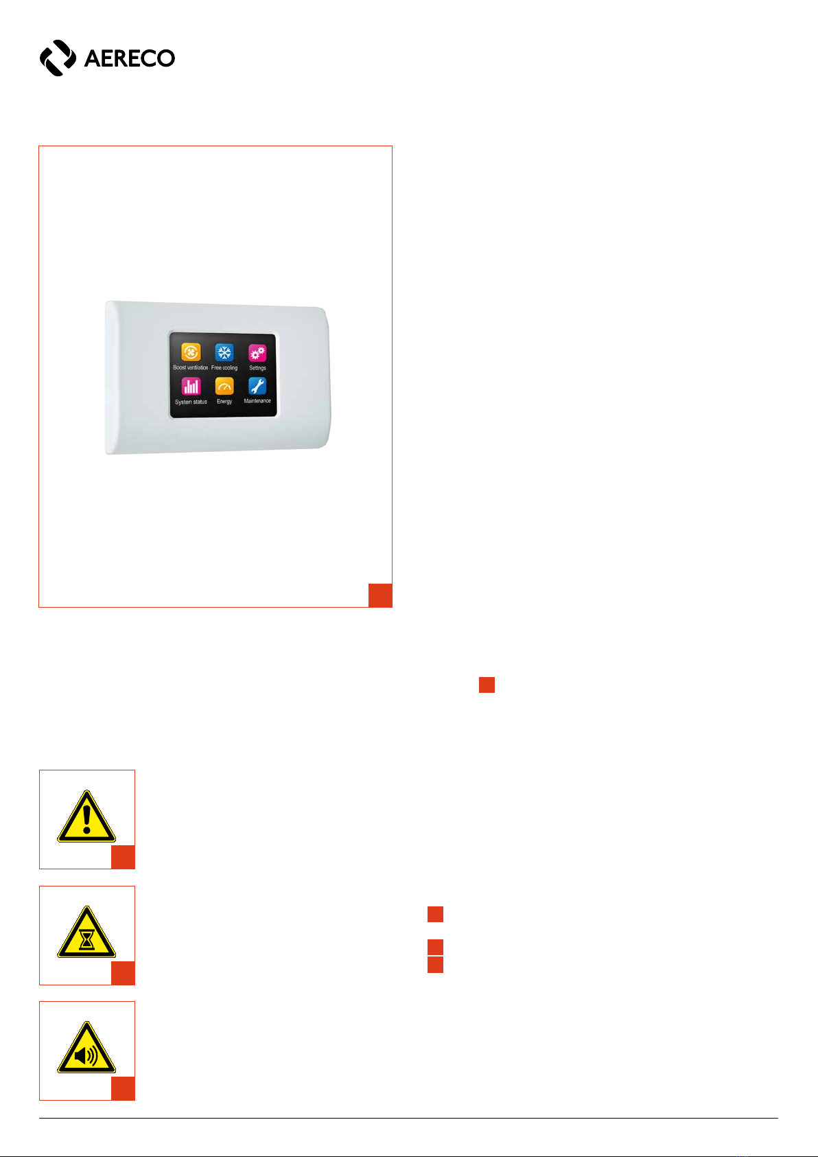
The graphic interface:
Figure 3: Touch-screen interface for the display, settings, and
diagnostic functions of the DXR.
The colour touch-screen interface is used to view system performance,
for diagnostics of its operation, and to adjust such parameters as the
automatic bypass temperature, or to start free cooling of the dwelling on
demand.
It also tells the occupant when it is time to replace the filters.
3. PICTOGRAMS
AWarning. Risk of deterioration of the appliance and impairment
of its eectiveness and life.
BLong initialization time (>10 minutes).
CRisk of noise.
Les débits d’air sont automatiquement modulés en fonction des besoins
de chaque pièce du logement : à l’insuation dans les chambres et le
séjour comme à l’extraction dans la cuisine, la salle de bain et les WC.
Chaque bouche d’insuation est directement raccordée à la boîte de
répartition DXR Hub : celle-ci adapte le débit d’air insué dans chaque
pièce principale en fonction du taux de CO2(E), de façon proportionnelle
au niveau mesuré. À l’extraction, les bouches BXC adaptent le débit d’air
en fonction de paramètres variables selon les pièces : humidité dans la
salle de bain, présence dans les toilettes, humidité et bouton poussoir
pour le débit de pointe dans la cuisine. Des versions avec détection de
CO2ou des COV peuvent également être utilisées à l’extraction.
À chaque instant, les débits totaux insués et extraits sont mesurés au
niveau du double flux pour être équilibrés au moyen de deux vannes de
compensation pilotées pouvant être situées en séjour, cuisine ou dans
un couloir. Ainsi, par exemple lorsque le besoin augmente en cuisine
lors de la préparation des repas sans être accompagné d’une forte
demande en chambre ou en séjour, le débit demandé à l’extraction peut
être assuré grâce à l’ouverture de la compensation (située dans le DXR
Hub) du réseau d’insuation.
Le bypass situé dans le double flux assure le shunt automatique de
l’échangeur dans les cas où la température extérieure est susamment
douce ; il peut également être actionné en mode free-cooling pour
assurer le rafraîchissement nocturne en été.
L’interface graphique :
Figure 3: Interface tactile pour l’achage, le paramétrage et le
diagnostic du DXR.
L’interface tactile couleur permet d’acher les performances du
système, de diagnostiquer son fonctionnement et de régler des
paramètres tels que la température de bypass automatique ou encore de
lancer un rafraîchissement du logement à la demande.
Elle avertit en outre l’occupant lorsque les filtres ont besoin d’être
remplacés.
3. PICTOGRAMMES
APoint d’attention. Risque de dégradation de l’appareil et de
mauvaises ecacité et longévité de l’appareil.
BDélai d’initialisation important (>10 minutes).
CRisque de gêne sonore.

8 / 52
DE
TF5822_B
4. ALLGEMEINER BETRIEB
Das Grafik-Display ist ein Touchpad. Das heißt, man kann die
gewünschten Vorgänge durch einfaches Antippen der Symbole
auslösen. Um die Parameter für einen Vorgang anzeigen zu
lassen, drückt man länger auf das betreende Symbol (zum
Beispiel beim Einstellen von Zeiträumen und Temperaturen).
Es empfiehlt sich, zum Betätigen der Befehle die Finger oder
einen Tablet-Stift zu verwenden. Verwenden Sie keinesfalls
Spitze oder scharfe Gegenstände, diese könnten das Display
beschädigen!
4.1. HAUPTMENÜ
Siehe Bild 4
Im Hauptmenü kann aus 6 Untermenüs gewählt werden:
A Intensivlüftung: In diesem Menü wird der Modus "Intensivlüftung" der
Zu- und Abluftanlage aktiviert.
BFree-Cooling: In diesem Menü wird der Modus "Nachtauskühlung"
im Rahmen der technischen Möglichkeiten der Zu- und Abluftanlage
aktiviert.
CEinstellungen: In diesem Menü können einige Parametereinstellungen
geändert werden.
DSystemstatus: In diesem Menü werden die statistischen Betriebsdaten
des Systems angeführt.
EEnergie: In diesem Menü werden die dank der Bedarfsführung
erzielten Energiegewinne angezeigt.
FWartung: In diesem Menü wird der Filterwechsel gesteuert.
4.2. AUFBAU DES BILDSCHIRMS UND NAVIGATION
ZWISCHEN DEN VERSCHIEDENEN MENÜS
Siehe Bild 5
ABeschreibung des Untermenüs.
BZurück zum Hauptmenü.
CBestätigen der gewählten Konfiguration.
DZurück zum vorigen Bildschirm.
Bemerkung: Wenn die Bestätigungsleiste nicht auf dem Bildschirm
erscheint, wählt man einfach das Bild aus und löst damit den nächsten
Vorgang aus.
A B C
D E F
A
B C D
4
5

9 / 52
FREN
TF5822_B
4. GENERAL OPERATION
The graphic interface uses a touch screen. Simply press one of
the icons to trigger the desired action. A long press on an icon
scrolls the possible values of a parameter (useful for example
when setting durations and temperatures).
We recommend using your fingers or a stylus to actuate the
commands. Avoid using sharp or cutting materials, which
might damage the surface.
4.1. MAIN MENU
See figure 4
The main menu has six user-activated sub-menus:
ABoost ventilation: this menu is used to activate the boost ventilation
mode of the heat-recovery.
BFree cooling: this menu is used to activate the free cooling mode of
the heat-recovery.
CSettings: this menu is used to modify the choice of some default
settings.
DSystem status: this menu displays the operating statistics of the
system.
EEnergy: this menu displays the energy savings achieved thanks to the
demand controlled heat-recovery.
FMaintenance: this menu is used to manage maintenance of the filters.
4.2. ORGANIZATION OF THE SCREEN AND NAVIGATION
BETWEEN THE MENUS
See figure 5
ADescription of the step.
BReturn to the main menu.
CConfirms the selected configuration.
DReturn to the previous screen.
Remark: If the validation bar is not visible on the screen, simply selecting
the image triggers the next action.
4. FONCTIONNEMENT GÉNÉRAL
L’interface graphique est tactile. Il sut d’appuyer sur les
icônes pour déclencher les actions désirées. L’appui prolongé
sur une icône permet de faire défiler un paramètre (par
exemple lors du réglage des durées et des températures).
L’usage des doigts ou d’un stylet est recommandé pour
actionner les commandes. Il est fortement déconseillé d’utiliser
des matériaux pointus ou coupants, qui pourraient détériorer le
support.
4.1. MENU PRINCIPAL
Voir figure 4
Le menu principal est composé de 6 sous-menus, activés par
l’utilisateur :
ASurventiler : ce menu permet d’activer le mode surventilation
du double flux.
BRafraîchir : ce menu permet d’activer le mode de rafraîchissement
du double flux.
CParamétrer : ce menu permet de modifier les choix de certains
paramètres initiaux.
DÉtat système : ce menu décrit les statistiques de fonctionnement
du système.
EÉnergie : ce menu ache les gains énergétiques réalisés grâce
au double flux modulé.
FMaintenance : ce menu permet de gérer la maintenance des filtres.
4.2. ORGANISATION DE L’ECRAN ET NAVIGATION ENTRE
LES MENUS
Voir figure 5
ADescription de l’étape.
BRetour au menu principal.
CValide la configuration choisie.
DRetour à l’écran précédent.
Remarque : Si la barre de validation ne figure pas sur l’écran, le simple
fait de sélectionner l’image déclenchera l’action suivante.

10 / 52
DE
TF5822_B
4.3. STANDBY
Das Touchpad-Display schaltet automatisch auf Standby, wenn es
30 Sekunden lang nicht verwendet wird. 3 Sekunden lang wird der
Bildschirmschoner angezeigt (Siehe Bild 6).Danach schaltet das
Display auf Energiesparmodus und der Bildschirm wird schwarz.
Solange der Bildschirmschoner zu sehen ist, kann der Benutzer zur
ursprünglich unternommenen Aufgabe zurückkehren, indem er das
Display berührt.
Wenn der Energiesparmodus zu sehen ist, kehrt man hingegen zum
Hauptmenü zurück.
5. INITIALISIERUNG
Im Initialisierungsmenü muss der Installateur die Standardeinstellungen
des Systems eingeben und den einwandfreien Betrieb des Systems
prüfen, Versorgung der Sensoren mit Spannung und Zuordnung der
Räume.
5.1. GRAFIK-DISPLAY ANSCHLIESSEN
Siehe Bild 7
Das Touch-Display wird mit einem RJ11-Kabel an der Rückseite des
Displays mit der XP-1 verbunden. An der Rückseite des Gehäuses ist ein
abtrennbarer Bereich als Kabeldurchlass vorgesehen.
Sobald das Touch-Display an die RJ11-Leitung angeschlossen ist, und
die XP-1 ebenfalls angeschlossen ist, schaltet sich der Bildschirm ein,
die Programmversion und die Systemangaben erscheinen in grüner
Schrift auf schwarzem Hintergrund.
Nach einigen Sekunden erscheint der erste Bildschirm. Für die
Initialisierung des Systems befolgen Sie die Anweisungen auf dem
Bildschirm.
5.2. SPRACHWAHL
Siehe Bild 8
Wählen Sie die Sprache, indem Sie auf das entsprechende Bild drücken.
Hinweis: Später kann diese Einstellung im Parametermenü wieder
geändert werden.
8
7
6

11 / 52
FREN
TF5822_B
4.3. STANDBY
After 30 seconds of non-use, the graphic interface automatically
switches to standby. The interface displays the standby screen for 3
seconds (see figure 6). After this time, the interface screen changes
to full standby (the screen turns black).
When the interface displays the standby screen, any user action on the
screen accesses the task previously initiated.
When the interface displays the black screen, any user action on the
screen causes a return to the main menu.
5. INITIALIZATION
The initialization menu allows the installer to enter the default settings of
the system and check the proper operation of the system (connection of
the sensors in the main rooms).
5.1. CONNECTING THE GRAPHIC INTERFACE
See figure 7
The graphic interface is connected to the DXR via an RJ11 cable on the
back of the interface. A knockout hole in the back of the support makes
it easy to insert the cable.
When the graphic interface is powered up through RJ 11 cable, the
screen lights and identifies the program version and displays the system
data (green characters on black ground).
After a few seconds, the first screen appears. Follow the instructions on
screen to initialize the system.
5.2. CHOICE OF LANGUAGE
See figure 8
Press the corresponding image to select the language.
Remark: This choice can be changed later, in the settings menu.
4.3. MISE EN VEILLE
Après 30 secondes de non utilisation, l’interface graphique se met
automatiquement en veille. Pendant 3 secondes, l’interface ache
l’écran de veille (voir figure 6).Passé ce délai, l’écran de l’interface
passe en veille prolongée (écran noir).
Lorsque l’interface ache l’écran de veille, toute action de l’utilisateur
sur l’écran permet d’accéder à la tâche précédemment initiée.
Lorsque l’interface ache l’écran noir, toute action de l’utilisateur sur
l’écran permet de revenir au menu principal.
5. INITIALISATION
Le menu d’initialisation permet à l’installateur d’entrer les paramètres
par défaut du système et de vérifier le bon fonctionnement du système
(connexion des capteurs dans les pièces principales).
5.1. BRANCHEMENT DE L’INTERFACE GRAPHIQUE
Voir figure 7
L’interface graphique est connectée au DXR via un câble RJ11 situé
au dos de l’interface. Un espace sécable au dos du support permet de
passer aisément le câble.
Lorsque l’interface graphique est sous tension via le câble RJ11, l’écran
s’allume et identifie la version de programme ainsi que les données du
système (écriture verte sur fond noir).
Après quelques secondes, le premier écran apparaît. Suivre les
indications à l’écran pour initialiser le système.
5.2. CHOIX DE LA LANGUE
Voir figure 8
Sélectionner la langue en appuyant sur l’image correspondante.
Remarque : Par la suite, cette donnée pourra être modifiée dans le
menu paramètres.

TF5822_B
12 / 52
5.3. MONTAGEDATUM
Siehe Bild 9
Geben Sie das aktuelle Datum mit Hilfe der Symbole und ein
(TT/MM/JJ).
Bestätigen Sie mit OK.
5.4. VORERHITZER
Siehe Bild 10
Geben Sie ein, ob in der Aussenluftansaugung ein Elektrisches
Vorheizregister vorhanden ist.
5.5. TEMPERATUREINHEIT WÄHLEN
Siehe Bild 11
Wählen Sie die im Land gebräuchliche Einheit (°C oder °F).
Hinweis: Später kann diese Einstellung im Parametermenü wieder
geändert werden.
11
10
9
DE

13 / 52
FREN
TF5822_B
5.3. DATE OF INSTALLATION
See figure 9
Enter the date of installation using the and icons
(dd/mm/yy).
Confirm by pressing “OK”.
5.4. DEFROSTING DEVICE
See figure 10
Indicate whether or not there is a defrosting device in the air supply
ducts.
5.5. CHOICE OF UNIT OF TEMPERATURE
See figure 11
Choose the customary unit in the country of installation (°C or °F).
Remark: This choice can be changed later, in the settings menu.
5.3. DATE D’INSTALLATION
Voir figure 9
Renseigner la date d’installation en utilisant les icônes et
(jj/mm/aa).
Valider en appuyant sur « OK ».
5.4. DISPOSITIF DE DÉGIVRAGE
Voir figure 10
Renseigner la présence ou non d’un dispositif de dégivrage dans le
conduit d’amenée d’air.
5.5. CHOIX DE L’UNITÉ DE TEMPÉRATURE
Voir figure 11
Choisir l’unité usuelle du pays d’installation (°C ou °F).
Remarque : Par la suite, cette donnée pourra être modifiée dans le
menu paramètres.

14 / 52
DE
TF5822_B
5.6. KONDENSATPUMPE
Siehe Bild 12
Geben Sie an, ob eine Kondensatpumpe an das System angeschlossen
ist.
5.7. ANZAHL DER ANGESCHLOSSENEN SENSOREN
BESTIMMEN
Bei diesem Menüpunkt wird die Anschlussqualität der mit RJ11-Kabeln
verbundenen CO2-Sensoren (Zulufträume) geprüft.
Siehe Bild 13
Geben Sie mit Hilfe der Symbole und die Anzahl der an die XP-1
angeschlossenen CO2-Sensoren an und bestätigen Sie dann mit OK.
Wenn die eingegebene Zahl mit den vom System tatsächlich erfassten
CO2-Sensoren übereinstimmt, kann der nächste Initialisierungsschritt
beginnen.
Sollte dies nicht der Fall sein und die eingegebene Zahl stimmt nicht mit
den vom System tatsächlich erfassten CO2-Sensoren überein, wird die
tatsächlich erfasste Anzahl auf einem roten Bildschirm angezeigt. Zwei
Vorgänge empfehlen sich:
• Verbindung der CO2-Sensoren überprüfen; diese müssen
sowohl an der XP-1 als auch am CO2-Sensor selbst
angeschlossen sein.
• Einstellung der Sensoren überprüfen (Indexierung 1-5, siehe
Bedienungs- und Wartungsanleitung der XP-1).
Bestätigen Sie diesen Schritt mit OK.
Daraufhin springt die Initialisierung zum vorhergehenden Schritt zurück
(Siehe Bild 13 ).
13
12

15 / 52
FREN
TF5822_B
5.6. CONDENSATION PUMP
See figure 12
Indicate whether a condensation pump is connected to the system.
5.7. DETERMINATION OF THE NUMBER OF SENSORS
CONNECTED
This step serves to check the connection of the sensors to the DXR via
the RJ11 cables.
See figure 13
Enter the number of CO2sensors connected to the DXR using the
and icons and confirm by pressing “OK”.
If the number of CO2 sensors entered matches to the number of sensors
detected by the system, the initialization process goes to the next step.
If the number of CO2sensors entered does not match the number
of sensors detected by the system, a red screen appears indicating
the number of sensors detected by the system. Two actions are then
recommended:
• Check that the sensors are correctly connected (connections
on the box and on the sensors themselves).
• Check the indexes of the sensors (index 1 to 5, see the
installation and maintenance manual of the DXR).
Confirm this step by pressing “OK”.
The initialization process returns to the previous step (see figure 13 ).
5.6. POMPE À CONDENSATS
Voir figure 12
Préciser si une pompe à condensats est raccordée au système.
5.7. DÉTERMINATION DU NOMBRE DE CAPTEURS
CONNECTÉS
Cette étape permet de vérifier le raccordement des capteurs CO2au DXR
via les câbles RJ11.
Voir figure 13
Renseigner le nombre de capteur CO2connectés au DXR en utilisant les
icônes et , et valider en appuyant sur « OK ».
Si le nombre de capteurs CO2renseignés correspond eectivement au
nombre de capteurs détectés par le système, l’initialisation passe à
l’étape suivante.
Si le nombre de capteurs CO2renseignés ne correspond pas au nombre
de capteurs détectés par le système, un écran rouge apparaît indiquant
le nombre de capteurs détectés par le système. Deux actions sont alors
conseillées :
• Vérifier que les capteurs CO2sont bien branchés au niveau
du caisson, ainsi qu’au niveau du capteur lui-même.
• Vérifier les indices des capteurs (Indices 1 à 5, voir notice
d’installation et de maintenance du DXR).
Valider cette étape en appuyant sur « OK ».
L’initialisation revient à l’étape précédente (voir figure 13 ).

16 / 52
DE
TF5822_B
5.8. ZUORDNUNG DER SENSOREN UND
ZULUFTELEMENTE
Bei diesem Schritt wird überprüft, dass die Zuordnung der Zulufträume
mit dem jeweiligen CO2-Sensor verbunden sind.
Bei jedem Zwischenschritt geben Sie bitte ein, ob das markierte Element
(blau, mit Nummer) ordentlich an das System angeschlossen ist und
überprüfen Sie die Einstellung (Indexierung 1-5) der Sensoren. Damit die
Zuordnung des entsprechenden Zuluftelementes einwandfrei zugeordnet
werden kann, wird die Luftmenge an diesem Zuluftelement erhöht,
gleichzeitig wird an allen anderen Zuluftelementen die Luftmenge
reduziert.
Siehe Bild 14 (Beispiel für Pos. 1)
Gehen Sie für alle Positionen der Reihe nach folgendermaßen vor:
1. Wenn die betreende Position nicht angeschlossen ist:
a. Wählen Sie "Nicht angeschlossen".
2. Wenn die betreende Position angeschlossen ist:
a. Suchen Sie das der aktuellen Position entsprechende
Zuluftelement (erkennbar am starken Luftstrom).
b. Überprüfen Sie im betreenden Raum den Sensorindex.
i. Wenn der Index stimmt, wenn er also der
aktuellen Position entspricht, wählen Sie "Erledigt".
ii. Wenn der Index falsch ist korrigieren Sie den
Indexierungsfehler und wählen Sie dann "Erledigt".
Hinweis: Die Montage muss einwandfrei nach den Regeln der Technik
erfolgt sein (keine Undichtigkeiten im Kanalnetz und Druckverluste
im Netz), damit die Zuordnung der Zuluftelemente mit den Sensoren
möglich ist.
Zum Abschluss dieses Arbeitsschrittes wird ein Überblick über die
Zuluftelement-Anschlüsse angezeigt. Farbpunkte zeigen an, ob die
betreenden Zuluftelemente korrekt in den Sensoren indexiert sind:
• Blauer Punkt: Das Element ist korrekt und in
Übereinstimmung mit dem entsprechenden CO2-Sensor
angeschlossen.
• Grauer Punkt: Das Element ist nicht angeschlossen, kein
CO2-Sensor vorhanden.
• Roter Punkt: Die Eingaben sind widersprüchlich:
1. Die eingegebene CO2-Sensoranzahl und die
eingegebene Zuluftelemente Anzahl
stimmen nicht überein.
2. Die eingegebenen Zuluftelemente entsprechen
nicht mit der CO2-Sensorindexierung überein.
Beispiel: Siehe Bild 15
Wenn die Zuordnung einwandfrei erfolgt ist, kann der nächste
Initialisierungsschritt beginnen.
14
15

17 / 52
FREN
TF5822_B
5.8. PAIRING OF SENSORS AND SUPPLY UNITS
This step serves to check the pairing of the supply units with their CO2
sensors.
Each intermediate step consists in indicating whether the unit that is
highlighted (by a numbered blue disc) is correctly connected to the
system, and checking the indexing of the sensors (1 to 5). To facilitate
locating the supply units, a strong stream of air emerges from the unit
concerned, while the other units deliver the minimum air flow.
See figure 14 (Example for position 1)
For each position, proceed as follows.
1. If the position in question is not connected:
a. Select “Not connected”.
2. If the position in question is connected:
a. Locate the supply unit corresponding to the position selected
(with the help of the high airflow delivered by the unit).
b. In the corresponding room, check the index of the sensor.
i. If the index is correct (i.e. matches the position in
question), select “Done”
ii. If the index is wrong, correct the indexing
of the sensor, then select “Done”.
NB: The unit/sensor pairing can be checked only if the system has been
installed in accordance with good practice (limiting leaks and losses of
head in the network).
A summary of the connections to the supply units is displayed at the end
of this step. It uses colour-coded discs to indicate whether the supply
units concerned correctly match the indexing of the sensors:
• Blue disc: the unit is correctly connected, matching the
corresponding CO2sensor.
• Grey disc: the unit is not connected, and there is no CO2
sensor corresponding to it.
• Red disc: the information entered is inconsistent:
1. The number of CO2sensors entered is dierent
from the number of air supply positions entered.
2. he air supply positions entered do not match the
indexing of the CO2sensors.
Example: See figure 15
If the pairing has been correctly entered, the initialization process goes
to the next step.
5.8. ASSOCIATION CAPTEURS - BOUCHES DE
SOUFFLAGE
Cette étape permet de vérifier l’association des bouches de souage
avec leur capteur CO2.
Chaque étape intermédiaire consiste à renseigner si la bouche mise
en surbrillance (par une pastille bleue numérotée) est correctement
connectée au système, et à vérifier l’indexation des capteurs (1 à 5).
Pour faciliter le repérage des bouches au souage, un jet d’air fort
est provoqué au niveau de la bouche concernée, tandis que les autres
bouches émettent un débit d’air minimal.
Voir figure 14 (Exemple pour la position 1)
Pour chaque position, procéder de la manière suivante.
1. Si la position considérée n’est pas connectée :
a. Sélectionner « Non connecté ».
2. Si la position considérée est connectée :
a. Repérer la bouche de souage correspondant à la position
sélectionnée (pour cela, s’aider du fort débit provoqué à la
bouche).
b. Dans la pièce correspondante, vérifier l’index du capteur.
i. Si l’index est correct (i.e. : il correspond à la
position considérée), sélectionner « Eectué »
ii. Si l’index est erroné, corriger l’indexation du
capteur, puis sélectionner « Eectué ».
NB : La vérification de l’association bouche / capteur n’est envisageable
que si l’installation a été correctement réalisée dans les règles de l’art
(limitation des fuites et des pertes de charge dans le réseau).
Un récapitulatif des connexions au niveau des bouches de souage
est aché à la fin de cette étape. Il indique par un code de pastilles
colorées si les bouches de souage concernées correspondent à
l’indexation correcte des capteurs :
• Pastille bleue : la bouche est correctement raccordée, en
accord avec le capteur CO2correspondant.
• Pastille grise : la bouche n’est pas raccordée, et aucun
capteur CO2ne lui correspond.
• Pastille rouge : les informations renseignées ne sont pas
cohérentes :
1. Le nombre de capteur CO2renseigné est diérent
du nombre de positions renseignées au souage.
2. Les positions renseignées au souage ne
correspondent pas à l’indexation des capteurs CO2.
Exemple : Voir figure 15
Dans le cas où l’association a été renseignée correctement,
l’initialisation passe à l’étape suivante.

18 / 52
DE
TF5822_B
Sollte dies nicht der Fall sein und die Zuordnung der CO2-Sensoren
zu den Zuluftelementen ist nicht einwandfrei erfolgt, wird der erfasste
Fehler auf einem roten Bildschirm angezeigt. Daraufhin springt die
Initialisierung zum Schritt 5.7 (Anzahl der angeschlossenen Sensoren
bestimmen) zurück.
5.9. FILTERTESTS
Bei diesem Schritt werden die Filtereigenschaften initialisiert, anhand
derer später im Betrieb der Verschmutzungsgrad der Filter eingeschätzt
werden kann.
Bei diesem Vorgang, wird die XP-1 auf max. Leistung
betrieben, dadurch kann es zu deutlicher
Geräuschentwicklung kommen. Nach Abschluss des
Testes wechselt die XP-1 auf den normalen Betriebszustand.
Es dauert etwa 12 Minuten.

19 / 52
FREN
TF5822_B
If the pairing of the supply units with the CO2sensors is not correctly
entered, a red screen is displayed, indicating the type of error detected.
The initialization process returns to step 5.7 Determination of the
number of sensors connected.
5.9. TEST OF THE FILTERS
This step consists in initializing the properties of the filters so that it will
later be possible to evaluate the clogging rate of the filters in operation.
This operation may be slightly noisy because the maximum
airflow rates are reached. The DXR will go back to a
normal mode at the end of the operation.
This operation takes approximately 12 minutes.
Dans le cas où l’association entre les bouches de souage et les
capteurs CO2n’est pas correctement renseignée, un écran rouge est
aché, décrivant le type d’erreur détectée. L’initialisation retourne à
l’étape 5.7 Détermination du nombre de capteurs connectés.
5.9. TEST FILTRES
Cette étape consiste à initialiser les propriétés des filtres pour
pouvoir par la suite évaluer le taux d’encrassement des filtres en
fonctionnement.
Cette opération peut être légèrement bruyante, car les débits
d’air maximum sont atteints. Une fois le test terminé, le DXR
retourne à un état de fonctionnement normal.
Cette opération nécessite une durée de 12 minutes environ.

20 / 52
DE
TF5822_B
6. BENUTZERMENÜ
6.1. INTENSIVLÜFTUNG
Bei der Intensivlüftung wird die Lüftung für eine bestimmte Zeit mit
höchster Luftmenge betrieben. Diese Betriebsart ist immer dann
nützlich, wenn die Luft in der Wohnung rasch erneuert werden soll, zum
Beispiel bei Bauarbeiten mit toxischen Substanzen.
Allerdings sollte die Intensivlüftung nicht bei Bauarbeiten
verwendet werden, bei der viel Staub gebildet wird
(Gipsarbeiten, Schleifen usw.).
6.1.1. EINSCHALTEN DER INTENSIVLÜFTUNG
Die Intensivlüftung wird im Hauptmenü mit dem entsprechenden Symbol
aktiviert .
Zum Aktivieren dieser Funktion drücken Sie auf "JA". Die Intensivlüftung
startet nach ungefähr 3 Minuten.
Wenn die Intensivlüftung aktiviert ist, blinkt das Symbol im Hauptmenü,
somit wird der Benutzer darüber informiert, dass die Intensivlüftung
aktiviert ist.
Bemerkung:
Die Aktivierung der Intensivlüftung dauert standardmäßig mind. 12
Stunden.
Beim Aktivieren der Intensivlüftung wird der Kühlungsmodus
abgeschaltet.
6.1.2. PARAMETRIEREN DER INTENSIVLÜFTUNG
Wie lange die Intensivlüftung laufen soll, kann im Menü "Parametrieren"
eingestellt werden. Dazu klicken Sie auf das entsprechende Symbol im
Hauptmenü .
Drücken Sie auf "Einstellungen".
Drücken Sie auf "Intensivlüftungsdauer einstellen".
Siehe Bild 16
Legen Sie die gewünschte Intensivlüftungsdauer mit den Symbolen
und fest.
Mindestdauer: 12 Stunden
Höchstdauer: 48 Stunden
Zwischenlängen: 18; 24; 36 Stunden
16
Other manuals for DXR
1
This manual suits for next models
1
Table of contents
Other Aereco Heating System manuals
Popular Heating System manuals by other brands

AC Infinity
AC Infinity SUNCORE user manual

Julabo
Julabo ME operating manual

Empire Comfort Systems
Empire Comfort Systems DV-822 installation instructions

Gree
Gree LIVV09HP115V1A installation manual

SaniJura
SaniJura ZEPHYR Instructions for installation and use

Anton Paar
Anton Paar DHS 1100 Instruction Manual and Safety Information