Aereco DXA 230 REFERENCE Technical specifications

INSTALLATION AND MAINTENANCE INSTRUCTION (ENGLISH VERSION)
dx system
DXA 230 REFERENCE
Constant airflows heat recovery ventilation for cupboard installation
TF6746_A_NOT_DXA230_REFERENCE Aereco S.A.

2 / 36
TF6746_A_NOT_DXA230_REFERENCE Aereco S.A.
1. Introduction 3
1.1. Warnings 3
1.2. Pictograms 3
2. Description 4
2.1. General information 4
2.2. Construction / Dimensions 6
2.3. DXA Assembling 6
3. Installation 7
3.1. Location of the installation 7
3.2. DXA Unit 7
3.2.1. Location 7
3.2.2. Accessibility 8
3.2.3. Fixing of the DXA Unit 8
3.2.4. Duct connections to the DXA Unit 11
3.2.5. Evacuation of condensates 11
3.3. Defrosting (optional) 12
3.4. Smart interface 13
3.5. 2I2O module 13
3.6. Special care for the ductwork 14
3.7. Fire protection 14
4. Electrical connections 15
4.1. Electrical connection on the DXA Unit 16
4.2. Electrical connection of the defrosting 17
4.3. Electrical connection of the condensate pump for DXA1705 17
5. Starting and settings of the DXA 18
5.1. Ways to access to the interface 18
5.2. DXA Home page 19
5.3. First start 21
5.4. How to bring up to date the versioning 21
6. Maintenance 22
6.1. Regular maintenance of the installation 22
6.2. Power supply and motor material protections 22
6.3. Filters 23
7. Troubleshooting 25
8. Acceptance of works 26
8.1. Visual inspection 26
8.2. Measurements 26
9. Specific recommendations for airtightness and insulation of the installation 27
9.1. Insulation of the installation 28
9.2. Airtightness of the installation 28
10. Supply and exhaust units 30
10.1. Supply units / exhaust grilles 31
10.2. Fresh air inlet and exhaust air outlet 31
11. Environmental concerns 32
12. Warranty 32
13. Conformity and standard 32
14. Characteristics 33

3 / 36
TF6746_A_NOT_DXA230_REFERENCE Aereco S.A.
1.1. WARNINGS
PLEASE READ THE FOLLOWING INSTRUCTIONS BEFORE THE
INSTALLATION:
In case of non-compliance with advice and warnings contained
in this manual, the manufacturer can not be considered
responsible for damages to persons or property.
The manual describes how to install, use and maintain correctly
the appliance. The only way to ensure the eciency and longevity
of the product is to comply with these requirements.
Do not use this appliance for any applications for which it is not
intended.
The system must be installed by experienced contractors, trained
in the specificities of the process and having the necessary skills
in aeraulics and electricity.
The use of gloves to carry on the installation is recommended.
After unpacking the appliance, make sure it is not damaged. Any
functional default must be reported to your reseller.
The use of an electrical appliance implies the following
fundamental rules:
· Do not touch the appliance with a wet or damp body (hands, feet,
etc.).
· This appliance can be used by children aged from 8 years and
above and persons with reduced physical, sensory or mental
capabilities or lack of experience and knowledge if they have
been given supervision or instruction concerning use of the
appliance in a safe way and understand the hazards involved.
· Children shall not play with the appliance.
· The electrical installation and electrical connections must
be carried out by a qualified technician according to the
manufacturer’s instructions and in compliance with the
characteristics listed on the nameplate of the unit.
· The Appliance shall be installed in accordance with national
wiring regulation (IEC60335-2-40).
· Before carrying out any operation on the appliance, unplug or
disconnect it from the power supply, and ensure it can not be
accidentally restored.
· Power cable modification or replacement must only be carried
out by qualified personnel or by After-sales Service in order to
avoid any accident.
· Cleaning and user maintenance shall not be made by children
without supervision.
1.2. PICTOGRAMS
Warnings
Risks of:
· Appliance damage
· Bad eciency and longevity of the appliance.
Risk of electric shock.
Electrical component: ground.
1. INTRODUCTION
This document presents the installation and maintenance schemes for the whole system.

4 / 36
TF6746_A_NOT_DXA230_REFERENCE Aereco S.A.
The Heat Recovery Unit : DXA Unit
The DXA has been specifically designed for wall or cupboards installation. Thanks to its wellfitted dimensions, the DXA can be installed in technical
rooms, wallmounte.
2. DESCRIPTION
2.1. GENERAL INFORMATION
The DX System is a range of smart heat recovery ventilation systems that continually supply pollen-free and dust-free preheated fresh air to living areas,
ensuring a comfortable feel-good climate.
The DXA REFERENCE is a heat recovery unit with constant airflows for vertical installation (on the wall) in the apartment or in the house, from 2to 6 main
rooms, and from 1 to 5 technical rooms (kitchen, bathroom, others wet rooms). The dwelling has to be limited to 2 floors (1 ground floor and 1 floor
maximum), and has a maximum surface of 210m². This HRV (Heat Recovery Ventilation)system can also be used in oces, hostels, etc., if the required
airflow is in accordance with the one oered by the system.
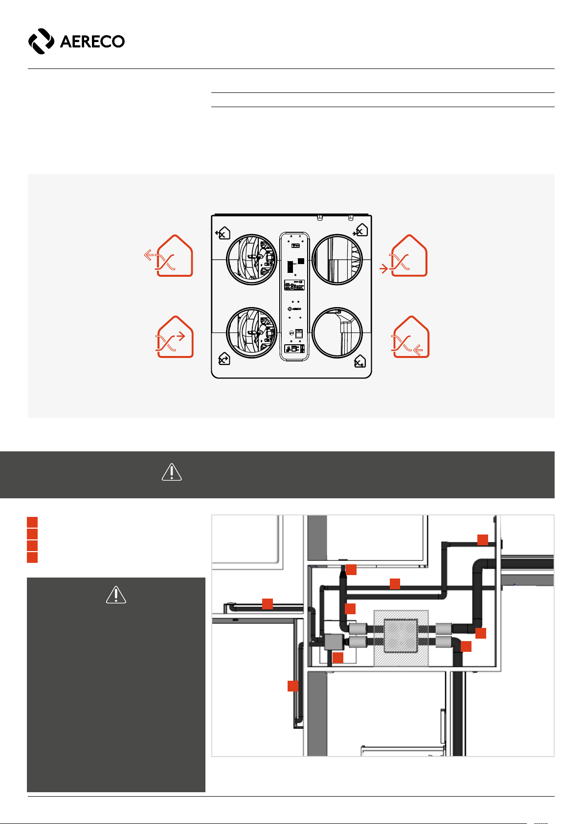
General working of the DXA System, REFERENCE Version
The DXA System is comprised of a heat recovery unit (DXA Unit 1 )
connected to exhaust and supply ductworks. The counter-flow heat
exchanger, integrated into the main unit, ensures the recovery and transfer
of most of the energy from the exhaust air to the supply air, thus limiting
the energy required to heat the fresh air.
According to the size of the dwelling and the number of occupants,
supply and exhaust airflows can easily be set from the interface (80 m3/h,
140 m3/h, 200 m3/h or 230 m3/h). Outdoor filtered air is supplied 3in
the bedrooms and in the living room. Stale air is extracted 7from the
kitchen, bathroom and WC.
At all times, total supply airflows and total exhaust airflows are measured
through pressure sensors placed in the DXA unit. The use of electronic
pressure sensors allows to calculate with a very high accuracy supply and
exhaust airflows without influence of clogging filters or ductwork pressure
drops. So, a dedicated micro-controller drives the two fan motors in such
a way that supply and exhaust massflows are balanced according to the
desired airflow setting point (80 m3/h, 140 m3/h, 200 m3/h or 230 m3/h).
The DXA Reference allows 4 specific regulation modes :
- Absence mode. This mode runs a 40 m3/h airflow ventilation for a
duration the customer may choose within a list of 1, 2, 3, 6, 14 or 30
days.
- Overventilation mode. This mode increase ventilation airflows staying
on the bypass rules. The customer may choose the over ventilation
airflows within a list of 140, 200, 230 or 250 m3/h for a duration he can
also choose (1, 2, 3, 6, 12 or 24 hours).
- Free cooling mode or Free warming mode. This mode is an over
ventilation mode enable only if temperature conditions allow to refresh or
to warm the dwelling.
- Stop mode. This mode allows to stop the fan motors. This mode may be
useful, for example not to clog the filters in case of works in the dwelling.

5 / 36
TF6746_A_NOT_DXA230_REFERENCE Aereco S.A.
2I2O
Modbus
Modbus
2 electric
wires
1
3
3
3
3
4
4
4
4
8
3
5
10
6 6
2
77
9
Typical apartment equipped with the DXA Unit, Reference version
Preheater + 2I2O Module
8
Distribution box (not specific)
2
Passive distribution box for supply airflows (may be replaced with T connections
DXA Unit
1
Heat recovery unit with balanced demand controlled airflows
4
SDC 100
3
Supply unit
Air intake
and outlet grilles
5Acoustic attenuation
6
Manual registrer for balancing
SDC
7
Exhaust units
Smart pannel interface
9
(Optional)
Galvanised steel body with built-in resistance (optional)
10 mA max
5V DC
OUT 1
OUT 2
IN 2
IN 1
0 Volt
2I2O MODULE
Power ON
Modbus trac
Modbus connection
List of components
supply aiflows
exhaust aiflows
technical room

6 / 36
TF6746_A_NOT_DXA230_REFERENCE Aereco S.A.
Dimensions of DXA Unit (mm)
2.2. CONSTRUCTION / DIMENSIONS
DXA Unit 230m3/h– Heat recovery unit
See the characteristics of the DXA Unit system on page 33
· Envelope in EPP.
· 2 low energy consumption fans driven by EC (electronic commutation) motors (supply air and
exhaust air).
· 2 F7 anti pollen filters for the fresh air.
· G4 filter for the exhaust to protect fans and the exchanger.
· Continously checking of filter clogging, and warning for filter change.
· Very high eciency heat exchanger with plastic plates, washable.
· Intelligent electronic control unit of the heat recovery, with integrated control interface.
· Integrated bypass and free-cooling automatically controlled.
ø160 ø160 88
248 151 155
1189
240
R2,50
80
1184
130
545
40
482
545
138 118
151
R80
248 155
554
R80
101
2.3. DXA ASSEMBLING
When delivered, the DXA Unit is furnished with 4 lipseals spigots.
Before removing the 4 plastic caps, pull out carefully the staples with
a screwdriver to not dammage the EPP material. No need to seal the
spigots once they are pushed in the inlets and outlets of the DXA, the
lipseals make it already airtight.
Assembling of the DXA spigots

7 / 36
TF6746_A_NOT_DXA230_REFERENCE Aereco S.A.
wall
(side view)
wall (top view)
3. INSTALLATION
3.1. LOCATION OF THE INSTALLATION
The unit must be installed into the heated space, in parts of the dwelling relatively
insensitive to noise, not in the unheated space (attic, etc.). Upper and lower
temperature limits for the main unit are 5°C and 50°C
Ductwork should be installed in the heated space. If not, they must be insulated
with 50mm minimum of glass wool (or equivalent). The non compliance with these
conditions leads to the degradation of the heat recovery performance.
Features and uses
DXA Unit
Max. altitude of the product installation 2000 m
Temperature range of the installation place 5°C – 50°C
Humidity range of the installation place 5% - 95%
3.2. DXA UNIT
The caps on the DXA Unit must stay during the entire duration of the work, in order to
keep dust and pollution from getting into the boxes.
3.2.1. LOCATION
Before the installation, be sure of the solidity of the wall where you plan to install the DXA
Unit.
· Weight of DXA Unit = 23 kg
The DXA Unit must be positioned exactly vertically (max 1° tolerance).
The non compliance to this requirement may lead to serious problems of condensate
evacuation.
Positionning of the DXA Unit
D = 5 mm
D = 5 mm

8 / 36
TF6746_A_NOT_DXA230_REFERENCE Aereco S.A.
3.2.2. ACCESSIBILITY
The DXA Unit must be positioned so that it is accessible for the maintenance and in case of
access or removal from the wall / false ceiling.
Recommendation for access hatches
The electrical connections must be easily accessible to be able to disconnect the DXA Unit from
the supply before any operation on the appliance. The circuit-breaker must be easily identified and
accessible.
3.2.3. FIXING OF THE DXA UNIT
The DXA Unit is fixed on a wall thanks to the use of two metal brackets, specific to Aereco. The first
bracket is fixed in the DXA while the second bracket is screwed in the wall. The two brackets are
assembled one within the other.
Quick suspension system proposed by Aereco
Wall
D > 15 cm
D > 2 cm

9 / 36
TF6746_A_NOT_DXA230_REFERENCE Aereco S.A.
Installation of the fixing system for the DXA Unit.
1
5 6
7 8
x2 x12 x12 x12
DXA Unit DXA Unit
2 3 4
Ø6 mm
Note : For plasterboard walls, molly metal anchors may be used instead of provided plastic anchors.

10 / 36
TF6746_A_NOT_DXA230_REFERENCE Aereco S.A.
3.2.4. DUCT CONNECTIONS TO THE DXA UNIT
The connections to the DXA Unit are all in Ø160 mm. Labels on the unit identify the 4 ducts to be
connected (fresh air, used air, supply air, exhaust air). Outdoor fresh air, used air and Supply
fresh air ducts must be insulated.
Fresh air
(outdoor to indoor)
Used air
(indoor to outdoor)
Fresh air supply
(outdoor to indoor)
Exhaust air
(indoor to outdoor)
DXA top view
Each supply unit can be connected to a distribution box by a Ø100mm for rigid duct or
by a Ø75mm duct for semi-rigid duct. Each semi-rigid duct cannot aord an airflow
bigger than 30m3/h.
1Ø100 or Ø75 mm
2Ø100 mm or Ø125 mm
3Ø160 mm
4Ø160 + 50mm insulation
All supply grilles have to be balanced to
reach the required airflow in each main
rooms (living room, bedrooms....). This may
be done by the use of manual registers,
blocks of foam, or grilles with nuts inside
allowing to adjust room by room supply
airflows in each main room.
All exhaust grilles have to be balanced to
reach the required airflow in each wet room
(kitchen, rest room, bathroom....). This may
be done by the use od manual registers,
blocks of foam, or grilles with nuts inside
allowing to adjust room by room exhaust
airflows in each wet room.
Duct diameters and recommendation concerning the type of ducts
1
1
1
1
2
2
3
4
4
Supply grille
Supply grille
Supply grille
Supply grille
Exhaust grille
Exhaust grille
to exhaust air outlet
to fresh air inlet

11 / 36
TF6746_A_NOT_DXA230_REFERENCE Aereco S.A.
In order to fully guarantee the acoustic quality of the installation, it is necessary to
attenuate airborne noise from the main unit by:
·20 dB at 500 Hz at supply
·15 dB at 500 Hz at exhaust
This can be done using a silencer or an equivalent length of acoustic duct between the
DXA Unit and the distribution box.
3.2.5. EVACUATION OF CONDENSATES
To evacuate condensates, a lift pump may be used. It is also possible to use a siphon to
evacuate them by gravity, but a minimum slope of about 3° is recommended for the good
evacuation of condensates.
To ensure watertight connections between the condensate evacuation pipe and the lift
pump or the siphon, the DXA Unit is delivered with these components already built-in.
The DXA1705 is equipped with a lift pump, while the DXA1706 is equipped with a siphon.
Only the evacuation pipe to the wastewater has to be realized. This evacuation must be
insulated if installed outside the heated volume (risk of freezing).
Using the lift pump (DXA1705)
· A vertical height of 8 meters must not exceed between the lift pump and the evacuation duct.
Note: The lift pump proposed by Aereco was tested and validated specially for DX System. Using
another lift pump can lead to serious problems of functioning and degrade the security of the
system. All the connections must be watertight.
Using the siphon (DXA1706)
The condensate ducts must not be higher than the DXA Unit evacuation outlet
Before fixing the DXA Unit on the wall, the siphon has to be filled with 0.5 L of water. A funnel can
be used to realise the operation.
Evacuation of condensates with the built-in siphon
Evacuation of condensates with a lift pump
(specific to Aereco)
max 8 m

12 / 36
TF6746_A_NOT_DXA230_REFERENCE Aereco S.A.
3.3. DEFROSTING (OPTIONAL)
The defrosting is located in the duct that serves the fresh air inlet, upstream from the DXA Unit. It is
therefore in Ø160 mm and insulated. A minimum length of 1 m must be respected between the
DXA Unit and the defrosting. The fresh air supply air duct must be manufactured from non-
flammable materials (A1 Class according to EN 13501-1).
The air must travel in the direction shown by the arrows marked on the defrosting device.
325
250
Ø160 mm
View of the defrosting
Positioning of the defrosting compared to the
DXA Unit
L > 1m
The defrosting must be located at a distance of at least twice the connection diameter from a duct
bend or external grille, and at 1m minimum length from the DXA Unit. We recommend tilting the
duct slightly towards the exterior in order to keep rain water from getting into the defrosting.
The installation must allow access to the defrosting for a manual reset, or for maintenance
(access hatch).
Manual reset of the defrosting:
1. Unscrew the black cap 2. Push the red button and screw back the
black cap on
The defrosting must not be installed with the
electrical device at the bottom.
Note:
· The DXA Unit has been specially designed to work with the defrosting provided by Aereco (defrost
strategy specific to DX System, and adapted diameter). Besides, it has been CEM certified with the
DXA Unit.
· Using another defrosting can lead to serious problems of functioning and degrade the security of
the system.
Anti-frost without pre-heating resistance
· When using the DXA Unit without the additional resistance pre-heating, the anti-frost strategy is
based on the supply airflow regulation. The supply air fan is switched o and the extract air fan
remains active, in order to warm up the heat exchanger.
Be careful, very often, this type of strategy does not comply with an open fireplace. Make
sure that you comply with the standard in force in the country of installation.
When the optional defrosting device is used, this anti-frost strategy is not active anymore.
A 1200W preheater allows to warm 200 m3/h @ -20°C. If T° can fall down bellow -20°C,
2 x 1200W preheaters may be implemented on the same supply duct network. These 2
preheaters can be driven with only one 2I2O module. In this situation, the amount power of
the 2 preheaters is 2400W, so this value has to be entered in the manufacturer access web
page (MAINTENANCE / MANUFACTURER ACCESS / Preheater power).

13 / 36
TF6746_A_NOT_DXA230_REFERENCE Aereco S.A.
3.4. SMART INTERFACE
As an optional component, a smart interface may be implemented on the bus network. The small
interface allows to enable the automatic mode, the absence mode, or the overventilation mode.
The smart interface provides information regarding filters clogging rate and warning messages.
3.5. 2I2O MODULE
Wi-Fi ON
OFF
ON
Modbus
connection
RJ45
cable
Bus
cap
bus cap
smart
interface
in 1 grey
black
Modbus cap
(or toward smart interface
Bus
cap
2x0,75mm2 wires
pump
end of pump
wires
230V 3x1,5mm2
to circuit breaker
IOA
output 1
ov
ov
Wi-Fi ON
OFF
ON
Pump (2I2O optionnal) only to display an error message if the pump is not OK
Preheater (mandatory to drive 1 or 2 preheaters)
2I2O
OV
in 1
in 2
out 2
out 1
+5V
2I2O
OV
in 1
in 2
out 2
out 1
+5V
RJ45 cable
bus cap (or toward
2I2O module)
· The 2I2O module may be used to display
pump warning message on the interface
(optional)
· The 2I2O module is mandatory to drive 1 or
2 preheaters
· Only one 2I2O module can be connected on
both a pump and 1 or 2 preheater.
Note : On the DXA unit, the RJ45 cable use to link the
2I2O module may be plug into any Modbus connection
outlet (up to the installer).
If the 2I2O module is not linked with another module
(smart interface for example), a Modbus cap must be
plug in the second RJ45 outlet of the 2I2O module.

14 / 36
TF6746_A_NOT_DXA230_REFERENCE Aereco S.A.
3.6. SPECIAL CARE FOR THE DUCTWORK
Any duct that is outdoors or in an unheated volume must be insulated with 50 mm of
glass wool or equivalent. In countries where the temperature can go under -10°C, the
recommendation of insulation is at least 100 mm of glass wool.
Mounting of ducts:
· The ductwork must be airtight (see recommendations for an airtight ductwork in page 27).
· Take care not to use a material that is too fragile or too flexible.
· The inner surfaces of all ducts must be as smooth as possible.
· Avoid having too many bends (make them gradual, with a large curvature).
· If using flexible duc:
-Avoid slopes (flexible ducts must be securely attached).
-Tauten the straight parts so that the duct is smooth and straight (when using flexible or
semi flexible ducts).
-If the flexible duct is longer than necessary, it must be cut rather than pushing the surplus
into the false ceiling.
-Do not crush the duct or squeeze it down to force it through a narrow passage.
· The interior of the ductwork must be protected during the entire duration of the work (from dust,
pollutants, etc.), using caps, plastic bags, or tape.
The installation of supply and exhaust units, and fresh air inlet and exhaust air outlet
must be carried out in order to obtain a system that performs well in terms of both
aeraulics and thermal and acoustic comfort (see recommendations for the installation
of the units in page 27).
3.7. FIRE PROTECTION
The installation must comply with the fire protection standards in force in the country concerned.

15 / 36
TF6746_A_NOT_DXA230_REFERENCE Aereco S.A.
230 VAC
D
E
230 VAC
in
out
RJ45
Modbus RJ45 cable
RJ45 cable
Smart interface
A
B
C
bus cap
bus cap
Wi-Fi ON
4. ELECTRICAL CONNECTIONS
Disconnect the electrical supply before any operations and ensure that the DXAUnit
cannot be started accidentally.
Only cables provided by Aereco must be used to carry on the DXA Unit installation. If using
dierent cables, Aereco won’t be able to guarantee the good functioning of the appliance.
The installation must be carried out by a professional in compliance with applicable
regulations in force in the country of installation. Each product or component used in the
installation must also comply with standards in force in the country.
ModBus components (2I2O module or
smart interface) may be connected on
one of the 2 RJ45 ModBus socket (the one
you want, it doesn't matter) for a parallel
wiring. But the ModBus components may
also be connected one after the other for a
serial wiring, up to you.
Each modbus line must be ended with a
ModBus cap. So, 2 ModBus caps must be
connected on the ModBus network (because 2
RJ45 ModBus sockets on the main electronic
board).
ADXA Unit
BSmart interface
C2I2O module
DDefrosting
ELift pump
RJ 45
Supply (230 V): 1.5 mm².
Note: RJ45 cables provide both supply and connections.
RJ45 maximal length: loop = 100m
bus cap
Modbus
RJ45
Modbus RJ45
Parallel wiring
bus cap
2I2O
Wi-Fi ON
Smart interface
Serial wiring
Modbus
cap
2I2O
Smart interface
Note: It's possible to connect the smart interface and the 2I2O module with a parallel or a serial wiring.

16 / 36
TF6746_A_NOT_DXA230_REFERENCE Aereco S.A.
4.1. ELECTRICAL CONNECTION ON THE DXA UNIT
1DX ModBus (RJ 45)
2Ethernet
3230VAC, 50/60Hz, 180W max
4ON / OFF
To circuit
breaker 2A
N
GND
L
3
2
1
230VAC 1.5mm²
230VAC 1.5mm²
230VAC 1.5mm²
4
Wi-Fi ON
OFF
ON
The main power supply is on the DXA Unit.
Smart Interface (optional) and 2I2O module (if pump or preheater).

17 / 36
TF6746_A_NOT_DXA230_REFERENCE Aereco S.A.
4.2. ELECTRICAL CONNECTION OF THE DEFROSTING
N - P
1 200 W
L1 - P
1 200 W
A1 +
A2 -
Defrosting unit
x1 or x2
DXA unit
230 VAC 3 x 1.5 mm²
To circuit breaker 10 A
Output 1
OV
RJ 45
cable
RJ 45
cable
bus cap
Hub cap
+
-
Wi-Fi ON
2I2O
OV
in 1
in 2
out 2
out 1
+5V
(2x0,75 mm² wires)
(2x0,75 mm² wires)
Details of DXA Unit and defrosting connection
The defrosting has an individual supply in 230 VAC, 50/60 Hz, single-phase via a flexible cable
having a cross-sectional area of at least 1.5 mm². The control is connected via a 2 wires cable
having a cross sectional area of at least 0.5 mm² and a maximal length of 30 meters.
The electrical connection must be made by a professional and comply with the standards in force
in the country of installation. Plan a contact separation device having an opening distance of at
least 3 mm on each pole.
Note: there is no alarm in the defrosting provided by Aereco.
Details of condensate pump electrical connections
4.3. ELECTRICAL CONNECTION OF THE CONDENSATE PUMP FOR DXA1705
THE DXA1706 is provided with a built in siphon. It is still possible to connect a condensate pump
after the siphon. The diagram below displays the electrical connections.
Dry contact alarm connections.
The alarm is connected via a 2 wires cable having a cross sectional area of at least 0.5 mm² and a
maximal length of 30 meters.
Wi-Fi ON
Hub cap
DXA Unit
in
OV
OV
in 1
in 1
in 2
out 2
out 1
+5V
OV
in 2
in 1
out 2
out 1
+5V
230VAC 3x1.5mm²
To circuit breaker 2A
L (Red), N(Blue) 230V 0.5mm²
Grey
black
black
Grey
L
N
GND
230VAC blue 1.5mm²
230VAC GND 1.5mm²
230VAC Brown 1.5mm²
2I2O
2I2O
On one of the 2 RJ45
Modbus socket
One of the 2 RJ45 Modbus socket may be
used for the 2I2O connection, and a modbus
cap must be plugged on the other RJ45
Modbus socket.

18 / 36
TF6746_A_NOT_DXA230_REFERENCE Aereco S.A.
5. STARTING AND SETTINGS OF THE DXA SYSTEM
5.1. WAYS TO ACCESS TO THE INTERFACE
Two kinds of connection are possible to acceed to the DXA's interface.
1) Communication through ethernet RJ45 cable
The RJ45 cable has to be plugged, on one side, in the DXA RJ45 socket (see scheme below) and,
on the other side, in the laptop's or computer's RJ45 socket.
From windows explorer, in the network, click on the DXA icon: another way is to use internet
browser.
On internet browser address bar (Edge, Chrome, Safari…), the following addresses give an access
to the settings and to the user home page of the DXA's interface:
· http://169.254.1.20/ to go to the Home page,
2) Communication through Wi-Fi connexion
From any smartphone or from a computer (or laptop), access to the available Wi-Fi network.
· Select the WiFi network named "DXA"
· The password to the WiFi is: 12345678
· On the device internet browser address bar (Android, Chrome, Safari…), the following addresses
give an access to the settings and to the user home page of the DXA's interface:
· http://dxr-mb.lan/ to go to the Home page,
Ethernet
Wi-Fi ON

19 / 36
TF6746_A_NOT_DXA230_REFERENCE Aereco S.A.
5.2. DXA HOME PAGE
1) HOME
The Home page gives a clear overview of the system :
-current mode of operation
-direct way to access
2) MAINTENANCE
To get in this section, the following mentions must be used
- Wifi connection
- to select the the Wifi / mode :
• AP mode (Access Point mode). The DXA unit provides its own Wifi network to be accessed with a
smart phone, a laptop, or a touch pad.
• ST mode (Station mode). The DXA unit is connected on the home internet box to access internet
This menu allows :
- To enable or disable the DXA Wi-Fi,
- To change the name of the DXA Wi-Fi (named DXA when the DXA unit is delivered),
- To change the Wi-Fi password (12345678 when the DXA unit is delivered).
- System parameters
This menu allows to access 4 advanced tools.
-Synoptic. This advanced tool allows to have an overview of the whole system, with all
parameters displayed. It’s also possible, with the set BUS values menu, to take under
control all driven parts (bypass, fan motors, defrosting unit).
-Synoptic data charts. This tool allows to display the evolution of the device parameters.
-Configuration wizard. The wizard allows to proceed to the DXA settings. Before starting
to run the DXA, make sure that all the ductwork have been correctly done. The Modbus
communication cable supplies the 2I2O module (if pump or preheater) and the smart
interface (if smart interface).
-Reset. This erase all configuration data kept in memory. A new configuration setting by the
use of the wizard is required after a reset.
- Maintenance
-Filter clogging level
-Filter status. Reset filters each time filters are replaced
-Bypass
-Preheater
- Manufacturer access.
-K factor is use to adjust airflows. (K=113 for DXA)
-Filters clogging threshold allows to display a warning message
-Preheater set point is the target to drive the preheater. This target is the average value of
the 2 cold T° (1/2 x (outside airflow T° before heat Exchanger + Inside airflow T° after heat
exchanger). This target is 2°C for the DXA when delivered by the factory.
-Preheater 1200W if 1 preheater (-20°C) / 2400W if 2 preheater (-38°C)
-Exterior T° set point fixes the minimal exterior T° to proceed free cooling (risk of
condensates outside of the ductwork if T° is too low) and if supply ductwork is not
insulated
-Interior T° set point to manage the bypass.
USER : 0aereco
PASSWORD : 0aereco123

20 / 36
TF6746_A_NOT_DXA230_REFERENCE Aereco S.A.
- General settings
- Email account settings
The emailing feature aims the communication of a possible system warning or a fatal error to the
interested people. We suggest one email address should specify the owner’s one and the second
email address should specify the technician in charge of the maintenance. The contact field may
contain some information providing the maintenance technician with the needed customer contact.
The essential points describing the emailing feature are:
1. The emailing of the warnings feature may be enabled/disabled.
2. When enabled, the system send email to one, two or three recipients. Two recipient email
addresses are configurable. The third recipient is the manufacturer, it is predefined and it is
mandatory when you enable this feature.
3. There is a button to test the configuration. When you click it, the system sends email letting you
to check the connectivity.
4. The information sent is:
a. Date and time,
b. Recipients email addresses
c. The text from the contact field
d. The status of the system including the event, the devices composing the system,
their serial number, hardware version, software version, functioning parameters when
the event happened. The status information is sent as a link onto the manufacturer
cloud.
5. The manufacturer collects only the status information in anonymous fashion. The text from
contact field and the email addresses are discarded.
6. To be able to email, the system needs to be connected to Internet through the local LAN (Station
Mode)
7. If you are concerned about the privacy issues you may simply disable the emailing system.
3) LANGUAGE :
Shortcut to Maintenance / general settings with no need of user name and password.
4) SETTINGS :
This menu allows to configure Automatic mode, free cooling mode, Boost mode, Absence mode
and Stop mode within a choice of airflows set points and duration set points.
Automatic mode, the DXA unit drives the exhaust fan motor in such a way that supplky and
exhaust airflows are constant airflows (80 m3/h, 140 m3/h, 200 m3/h or 230 m3/h). At the supply,
supply fan motor runs in such a way that at all time, amount exhaust airflows and amount supply
airflows are mass-balanced.
Table of contents
Other Aereco Heating System manuals
Popular Heating System manuals by other brands

Carrier
Carrier GT-G user manual

Roberts Gorden
Roberts Gorden CoRayVac CRV-B-2 Design manual

Ferroli
Ferroli UT REC micro E 25H Instructions for installation, use and maintenance manual

Jakka
Jakka JRH73 Series user manual

Firesense
Firesense Mojave Sun IR MS-1500WOIRPH Assembly instructions

Heat & Glo
Heat & Glo PRIMO Series installation instructions

CALEFFI
CALEFFI SATK22107 INSTRUCTIONS FOR INSTALLATION, COMMISSIONING AND MAINTENANCE

Baxi
Baxi Assure FGHR Fitting instructions

S&P
S&P CADB-N-D installation manual

Rinnai
Rinnai IB35RBN OWNER'S OPERATION AND INSTALLATION MANUAL

Carrier
Carrier WEATHERMAKER 48A2 Series Wiring diagrams

Energotech
Energotech EnergoStrip EE-2 Mounting and installation