Aerial Airborne Wakeboard Tower User manual

installation guide
GUIDE#: PWB-AIRBORNE-V1-004
1
airborne WaKeboard toWer
installation suPPort
SHOWN WITH OPTIONAL ACCESSORIES

GUIDE#: PWB-AIRBORNE-V1-004
2
This measurement is taken from the Port to Starboard mounting points.
Aerial does not cover damage caused by burrs during installation.
. We CANNOT be liable for any burring or scratch-
ing that may occur when sliding sections in and out of each other.
cleaning
Warning

GUIDE#: PWB-AIRBORNE-V1-004
3
note: LUBRICATE PARTS WITH A
LIGHT GREASE BEFORE ASSEMBLY
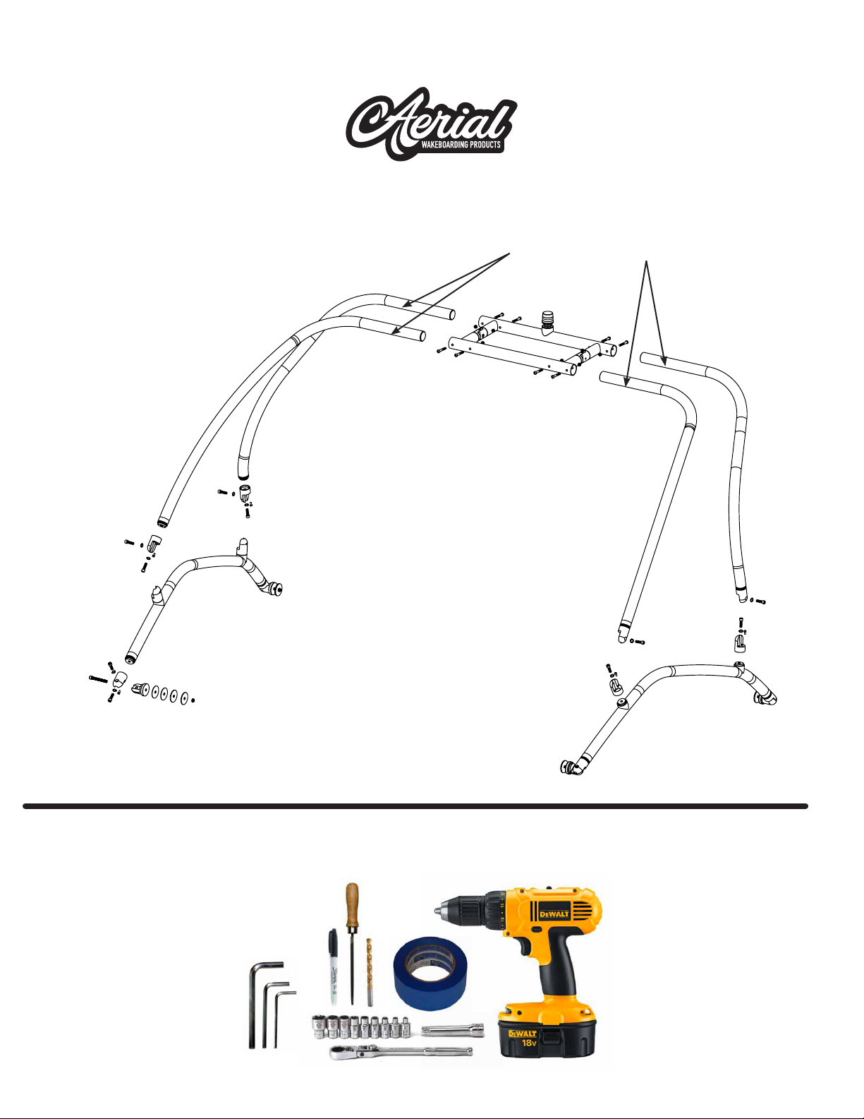
eXPloded oVerVieW
tools reQuired

GUIDE#: PWB-AIRBORNE-V1-004
4
STNEMMOCYTQNOITPIRCSED#METI
1 2.25" TOWER JOINT - THREADED (INCL. M6 X 12mm BOLT) 4
2 2.25" TOWER JOINT - THRU HOLE (INCL. M6 X 12mm BOLT) 8
4TNUOMKCED3
2,1-SMETIHTIWESUROF61TLOBmm04X21M4
3-SMETIHTIWESUROF4TLOBmm54X21M5
3-SMETIHTIWESUROF4TLOBmm57&X21M6
6,5,4-SMETIHTIWESUROF42REHSAWKCOLGNIRPS21M7
91-SMETIHTIWESUROF8TLOBDAEHNOTTUBmm57X01M8
8-SMETIHTIWESUROF8TUNKCOLNOLYN01M9
6-SMETIHTIWESUROF4TUNKCOLNOLYN21M01
6-SMETIHTIWESUROF4REHSAWTALFNOLY
N21M11
3-SMETIHTIWESUROF4)mm07=DO(REHSAWTALFNOLYNEGRAL21
3-SMETIHTIWESUROF4)mm07=DO(REHSAWREBBURDEVRUC31
3-SMETIHTIWESUROF4)mm07=DO(REHSAWTALFMUNIMULAEGRAL41
1YEKNELLA21M51
1YEKNELLA8M61
1YEKNELLA6M71
1REKCOLDAERHT81
1EBUTNOITCESPOT91
2SLIAREDISREWOL02
DRAOBRATS1&TROP12SGELTNORF12
DRAOBRATS1&TROP12SGELRAER22
TOWER PACKAGE
Parts list

GUIDE#: PWB-AIRBORNE-V1-004
5
Parts list
STARBOARD FRONT LEG PORT REAR LEG STARBOARD REAR LEGPORT FRONT LEG
TOP SECTION SIDE RAILS

GUIDE#: PWB-AIRBORNE-V1-004
6
Assemble the side rails to the deck mounts.
Note: these should only be loosely tightened at
this stage as they will require further adjustment
in the following stages of assembly.
Tape off all the areas that may potentially come into
contact with the side rails.
Once the feet are connected to the side rails, hold
the side rail up to your boat. Once the rail is aligned
with your windshield use a small piece of tape to mark
the position of the mounting feet.
LOWER SIDE RAIL
M12 X 45MM
M12 X 40MM
SPLIT LOCK WASHER
MOUNT
FITTING

GUIDE#: PWB-AIRBORNE-V1-004
7
steP 4
Once the desired position is achieved, place one of
the large nylon whasers over the piece of tape and
trace around it with a permanent marker.
This step is very important! After taping the second
side of the boat in approximately the same areas as
the rst side you will need to measure the distance
that you marked on the rst side of the boat
It is best to take measurements from the back of the
boat and mark with blue tape. Be sure to measure
from the same point on both sides.

GUIDE#: PWB-AIRBORNE-V1-004
8
Once you have marked your 4 holes, check the
underside of the deck for wires.
If necessary, you should move the wires out of
the way while you drill. We recommend drilling a small
pilot hole which will keep the 17/32” drill bit from walk-
ing (moving). A small rat tail le can be used to ease
the edge and keep the gel coat from chipping.
Be careful of wires!
A B C
Gelcoat
Fibreglass
Pilot Hole
countersinK
(tHrougH gelcoat)

GUIDE#: PWB-AIRBORNE-V1-004
9
Measuring from your windshield, check the distance
to the side rail to make sure both sides are symmetric.
Install the tower mounts to the boat deck in the order shown in the diagram.
Note: in the case where the deck of your boat is less than 1/4” thick, a reinforcing kit
is required to thicken and reinforce the deck in the mounting locations.
M12 X 75MM
M12 X 75MM
BLACK NYLON WASHER
BLACK NYLON WASHER
MOUNT
MOUNT
NYLON WASHER
NYLON WASHER
FLAT DECK
CURVED RUBBER WASHER
CURVED DECK
REINFORCEMENT REINFORCEMENT
RUBBER WASHER RUBBER WASHER
ALUMINUM BACKING PLATE ALUMINUM BACKING PLATE
SPLIT LOCK WASHER SPLIT LOCK WASHER
NYLON LOCK NUT NYLON LOCK NUT

GUIDE#: PWB-AIRBORNE-V1-004
10
steP 9
The side rails need to be mounted straight up and
down. If they are leaning in or out, this will cause a
problem with the tower when you want to fold it.
Assemble the hinge joints to
the end of the side sections.
Assemble the hinge joint
ttings onto the side rails.
M12 X 40MM
M12 X 40MM
M12 X 40MM
M12 X 40MM
M6 X 12MM
M6 X 12MM
SPLIT LOCK WASHER
SPLIT LOCK WASHER
SPLIT LOCK
WASHER
SPLIT LOCK WASHER
2.25” TOWER JOINT - THRU HOLE
FRONT LEG
REAR LEG
LOWER SIDE RAIL
M6 X 12MM
M6 X 12MM
SPLIT LOCK WASHER
SPLIT LOCK WASHER
2.25” TOWER JOINT - THREADED
M12 X 40MM
M12 X 40MM

GUIDE#: PWB-AIRBORNE-V1-004
11
Make sure that there are no burrs on the inside of the
top section tubes.
Someone will need to hold the top section for you as
you insert the front arms into the top section and con-
nect the hinge ttings into the side rails.
Do the same for the rear arms. It is important to try to
keep the top section centered on the boat during this
process.
Note: the top section can be rotated up or down to be
parallel with the boat.
The X measurement is a great way to make sure that
your tow point is in the center of your boat. To do this,
measure from the tow point to your rear foot, then to
your other foot. Cover your boat with an old sheet or
old cover to make removing the metal shavings easy.
Someone should hold the top section while you drill.
IMAGE SHOWS THE
SIDE SECTION BEING
ATTACHED TO THE
SIDE RAIL.

GUIDE#: PWB-AIRBORNE-V1-004
12
Use a smaller bit to make a pilot hole, then use your
27/64” bit.
After each hole is drilled, insert the 4 bolts into the top
section to keep it from moving.
Once all bolts are in place, tighten them with a socket
wrench and an Allen key.

GUIDE#: PWB-AIRBORNE-V1-004
13
Loosen the rear tower hinges about 1/4 turn. The front tower hinges need to be disconnected
with the help of an Allen key to allow the tower to fold back.
Once the tower is folded back, remove the 2 Allen bolts from the top section hinge which will
allow the arms to fold down for storage.
Once you are happy with your tower installation and all
of the ttings are lined up to allow the tower to fold and
function correctly it will then be important to rmly lock the
rotating ttings in place to prevent any unwanted rota-
tion or loosening. To do this the M12 x 40mm bolts that run
through the center of the ttings will need to be rmly tight-
ened. Next, the pre-instaleld M6 x 10mm fasteners found
in the ttings will then need to be rmly tightened with an
Allen key. We recommend using threadlocker during this
step.
M6 X 12MM

GUIDE#: PWB-AIRBORNE-V1-004
14
Questions?
installing tHe naVigation ligHt
The navigation light is shipped separately.
It is designed to be installed on the top of the tow point.
For a clean wiring installation the wires supplied can be passed through the
center of the tow point, along the inside of the top section and down inside
the leg tube. The wires will need to exit the leg tube just above the ttings
and then be passed over the ttings before entering back into the side rail
tube. Finally the wires will exit the side rail tube just above the mounting foot
and then enter the deck of the boat (through a hole that will need to be
drilled) so that they can be connected to a switch and power source.
Note: The tower is not supplied with pre-drilled wiring holes as each customer
may have a different wiring requirement depending on how they fold their
tower or the accessories that they will mount to the tower.
NAVIGATION LIGHT
(SHIPPED SEPARATELY)
Table of contents
Other Aerial Boating Equipment manuals
Popular Boating Equipment manuals by other brands

Ultraflex
Ultraflex UC130-SVS Installation and maintenance manual

Lippert
Lippert SureShade Power Bimini owner's manual

Vetus
Vetus BOW16024C Operation manual and installation instructions

Quick
Quick HECTOR 1700 Series user manual

SLEIPNER MOTOR AS
SLEIPNER MOTOR AS SIDE-POWER SE-50/140 S Installation and user manual

Vetus
Vetus V-QUIPMENT Light LCS Series installation instructions

CIPTA PERNIKA NUSANTARA
CIPTA PERNIKA NUSANTARA SMART VMS manual

Shoremaster
Shoremaster Bow Guide 7k Vertical instructions

MINN KOTA
MINN KOTA TALON owner's manual

Bennett Marine
Bennett Marine AutoTrimPro Installation & user guide

Origin
Origin Catapult installation guide

Maretron
Maretron FFM100 user manual