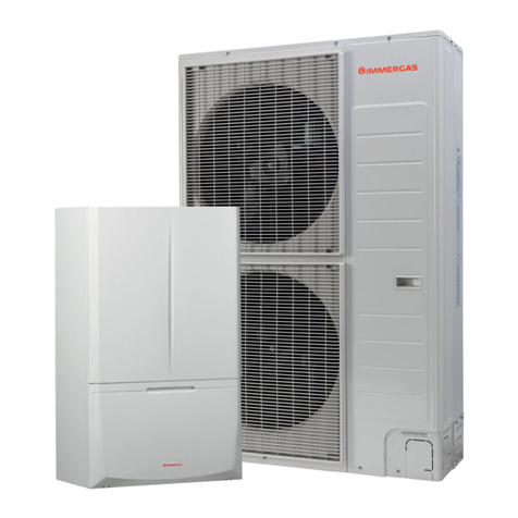
AERMEC Omnia UL 11 C Technical specifications

Omnia UL 11 C
Omnia UL 16 C
Omnia UL 26 C
Omnia UL 36 C
MANUALE D’USO E INSTALLAZIONE
USE AND INSTALLATION MANUAL
MANUEL D’UTILISATION ET D’INSTALLATION
MANUAL DE INSTRUCCIONES E INSTALACIÓN
VENTILCONVETTORE PER INSTALLAZIONE UNIVERSALE
FAN COIL FOR UNIVERSAL INSTALLATION
POUR INSTALLATION UNIVERSELLE
GEBLÄSEKONVEKTOR FÜR UNIVERSELLEN EINBAU
FAN COIL PARA INSTALACIÓN UNIVERSAL
IULCLX 1905 - 6976405_03
Omnia UL C
Please fill out the requested information

TRASPORTO • TRANSPORT • TRANSPORT • TRANSPORT • TRANSPORTE
NON bagnare. Tenere
al riparo dalla pioggia.
KEEP DRY. Keep out of
the rain.
NE PAS mouiller. Tenir à
l’abri de la pluie.
NICHT nass machen.
Vor Regen geschützt
anbringen
NO mojar. Conservar
protegido de la lluvia.
NON calpestare. DO NOT step on unit. NE PAS marcher
sur l’appareil. NICHT betreten . NO pisar.
N
Sovrapponibilità:
controllare sull’imballo
per conoscere il
numero di macchine
impilabili.
Stackability: check the
package to know the
number of stackable
machines.
Empilement : vérifier
sur l’emballage le
nombre
d’appareils empilables.
Stapelbarkeit: Auf
der Verpackung
nachsehen, wie die
Anzahl der stapelbaren
Geräte lautet.
Superponibilidad:
observar en el
embalaje la cantidad
de máquinas que
pueden apilarse.
>25Kg
NON trasportare la
macchina da soli se il
suo peso supera i 25Kg.
DO NOT carry the
equipment alone if
weight exceeds 25Kg.
NE PAS faire transporter
l’appareil par une seule
personne si son poids
est supérieur à 25kg.
NICHT das Gerät allein
transportieren, wenn
sein Gewicht die 25kg
übersteigt.
NO transportar la
máquina solos si su
peso es superior a los
25Kg.
NON lasciare gli imballi
sciolti durante il
trasporto.
Non rovesciare.
DO NOT leave boxes
unsecured during
transportation.
Do not overturn.
NE PAS laisser les
emballages sans
attaches durant le
transport.
Ne pas renverser.
NICHT die
Verpackungen
während des
Transports geöffnet
lassen.
Nicht stürzen.
NO dejar los embalajes
sin sujetar durante el
transporte.
No invertir.
Fragile, maneggiare
con cura.
Fragile, handle with
care.
Fragile, manipuler avec
soin.
Zerbrechlich, sorgfältig
handhaben.
Frágil, manipular con
cuidado.
SIMBOLI DI SICUREZZA • SAFETY SYMBOL • SIMBOIES DE SECURITE • SICHERHEITSSYMBOLEOLE •
SÍMBOLOS DE SEGURIDAD
Pericolo:
Tensione
Danger:
Power supply
Danger:
Tension
Gefahr !
Spannung
Peligro:
Tensión
Pericolo:
Organi in movimento
Danger:
Movings parts
Danger:
Organes en
mouvement
Gefahr !
Rotierende Teile
Peligro:
Elementos en
movimiento
Pericolo!!! Danger!!! Danger!!! Gefahr!!! Peligro!!!
Imballo: indicazioni per
trasporto e stoccaggio
Packing: indications for
transport and storage
Emballage: indications
pour le transport et le
stockage
Verpackung:
Anweisungen für
Transport und
Lagerung
Embalaje: indicaciones
para el transporte y el
almacenamiento

INDICE
VENTILCONVETTORE OMNIA UL C .......................................................................................................................................................................................................................4
COMANDI E VISUALIZZAZIONI................................................................................................................................................................................................................................4
UTILIZZO (OMNIA UL C) ............................................................................................................................................................................................................................................5
VISUALIZZAZIONI LUMINOSE..................................................................................................................................................................................................................................5
CARATTERISTICHE DI FUNZIONAMENTO............................................................................................................................................................................................................6
IMBALLO .........................................................................................................................................................................................................................................................................6
INSTALLAZIONE DELL’UNITÀ ...................................................................................................................................................................................................................................6
COLLEGAMENTI ELETTRICI.......................................................................................................................................................................................................................................7
ROTAZIONE DELLA BATTERIA..................................................................................................................................................................................................................................7
CONFIGURAZIONE DIP-SWITCH.............................................................................................................................................................................................................................8
AUTOTEST ......................................................................................................................................................................................................................................................................8
INFORMAZIONI IMPORTANTI E MANUTENZIONE............................................................................................................................................................................................9
LIMITI DI FUNZIONAMENTO....................................................................................................................................................................................................................................9
CONTENTS
OMNIA UL C FANCOIL............................................................................................................................................................................................................................................ 10
COMMANDS AND VISUALISATION ..................................................................................................................................................................................................................... 10
USE (OMNIA UL C).................................................................................................................................................................................................................................................... 11
DISPLAYS ..................................................................................................................................................................................................................................................................... 11
PACKAGING................................................................................................................................................................................................................................................................. 12
INSTALLATION............................................................................................................................................................................................................................................................ 12
ELECTRICAL CONNECTIONS ................................................................................................................................................................................................................................. 12
COIL ROTATION.......................................................................................................................................................................................................................................................... 12
OPERATION................................................................................................................................................................................................................................................................. 13
DIP-SWITCH SETTINGS............................................................................................................................................................................................................................................ 14
AUTOTEST FUNCTION............................................................................................................................................................................................................................................. 14
IMPORTANT MAINTENANCE INFORMATION................................................................................................................................................................................................... 15
OPERATING LIMITS .................................................................................................................................................................................................................................................. 15
INDEX
VENTILO-CONVECTEUR OMNIA UL C............................................................................................................................................................................................................... 16
COMMANDES ET VISUALISATIONS..................................................................................................................................................................................................................... 16
EMPLOI (OMNIA UL C)............................................................................................................................................................................................................................................. 17
VISUALISATIONS LUMINEUSES ............................................................................................................................................................................................................................ 17
CARACTERISTIQUES DE FONCTIONNEMENT.................................................................................................................................................................................................. 18
EMBALLAGE................................................................................................................................................................................................................................................................ 18
INSTALLATION DE L'UNITE..................................................................................................................................................................................................................................... 18
CONNEXIONS ELECTRIQUES................................................................................................................................................................................................................................. 19
ROTATION DE LA BATTERIE ................................................................................................................................................................................................................................... 19
CONFIGURATION DIP .............................................................................................................................................................................................................................................. 20
INFORMATIONS IMPORTANTES SUR LA MAINTENANCE ............................................................................................................................................................................ 21
INHALTSVERZEICHN
GEBLÄSEKONVEKTOR OMNIA UL C................................................................................................................................................................................................................... 22
BETRIEBSWEISE ......................................................................................................................................................................................................................................................... 22
ANWENDUNG (OMNIA UL C)................................................................................................................................................................................................................................ 23
LEUCHTANZEIGEN.................................................................................................................................................................................................................................................... 23
VERPACKUNG............................................................................................................................................................................................................................................................. 24
INSTALLATION DER EINHEIT.................................................................................................................................................................................................................................. 24
UMDREHEN DES WÄRMETAUSCHERS ............................................................................................................................................................................................................... 24
FUNKTIONSEIGENSCHAFTEN............................................................................................................................................................................................................................... 25
EINSTELLUNGEN DIP-SCHALTER ......................................................................................................................................................................................................................... 26
WICHTIGE HINWEISE UND WARTUNG............................................................................................................................................................................................................... 27
dati dimensionali • dimensions • dimensions • abmessungen [mm]............................................................................................................................................... 28
dati dimensionali • dimensions • dimensions • abmessungen [mm]............................................................................................................................................... 29
schemi elettrici • wiring diagrams • schemas electriques • schaltplÄne............................................................................................................................................... 30

A
B
CD
4
VENTILCONVETTORE OMNIA UL C
Il ventilconvettore OMNIA UL C concentra elevate caratteristi-
che tecnologiche e funzionali che ne fanno il mezzo ideale di cli-
matizzazione per ogni ambiente.
L’erogazione di aria climatizzata è immediata e distribuita in
tutto il locale; OMNIA UL C genera calore se inserito in un
impianto termico con caldaia o pompa di calore ma può essere
usato anche nei mesi estivi come condizionatore se l’impianto
termico è dotato di un refrigeratore d’acqua.
Il filtro è facilmente estraibile ed è costruito con materiali rige-
nerabili, può essere pulito mediante lavaggio; a ventilconvettore
spento le alette chiuse impediscono alla polvere e a corpi estra-
nei di penetrare all’interno. La possibilità di rimuovere la baci-
nella e le coclee dei ventilatori ispezionabili (eseguibile solo da
personale specializzato) consentono di eseguire una pulizia
accurata anche delle parti interne, condizione necessaria per
installazioni in luoghi molto affollati o che richiedono uno stan-
dard elevato di igiene.
La silenziosità del nuovo gruppo di ventilazione centrifugo è
tale che alla normale velocità di utilizzo, non si percepisce quan-
do l’OMNIA UL C entra in funzione. L’utilizzo di pannelli di con-
trollo elettronici evita il fastidioso rumore tipico dei termostati
meccanici.
Il pannello comandi con termostato elettronico è protetto da
uno sportellino sulla testata e consente la regolazione elettroni-
ca della temperatura, cambio di velocità automatica sul ventila-
tore, cambio di stagione automatico e accensione - spegnimen-
to automatico.
Il ventilconvettore OMNIA UL C è concepito per soddisfare
ogni esigenza di impianto, grazie anche alla ricca dotazione di
accessori.
Facilità di installazione con attacchi idraulici reversibili in fase
di installazione.
Pieno rispetto delle norme antinfortunistiche.
La manutenzione ordinaria è ridotta alla pulizia periodica del
filtro dell’aria con un semplice lavaggio in acqua.
COMANDI E VISUALIZZAZIONI
(A) Selettore della velocità;
(B) Selettore della temperatura
(C) Spia indicatore del modo di funzionamento
(D) Spia indicazione richiesta di ventilazione
Il ventilconvettore è spento. Può però ripartire in modalità
Caldo (funzione Antigelo) se la temperatura ambiente diventa
inferiore a 7°C e la temperatura dell’acqua è idonea, in questo
caso il led rosso lampeggia. Per avviare il ventilconvettore ruotare
la manopola verso il modo di funzionamento desiderato in posi-
zione AUTO o in una delle tre velocità di ventilazione.
Il termostato mantiene la temperatura impostata cam-
biando la velocità del ventilatore in Modo Automatico, in funzio-
ne della temperatura ambiente e di quella impostata.
V1 In questa posizione rimane sempre attiva la velocità minima di
ventilazione indipendentemente dalle richieste termostato.
V2 In questa posizione rimane sempre attiva la velocità media di
ventilazione indipendentemente dalle richieste termostato
V3 In questa posizione rimane sempre attiva la velocità massima
di ventilazione indipendentemente dalle richieste termostato
In questa posizione rimane sempre attiva la velocità minima di
ventilazione V1.
Selezione della temperatura ambiente desiderata.
Visualizza il modo di funzionamento CALDO/FREDDO richiesto dal
termostato elettronico e se l’impianto termico è in grado di sod-
disfare la richiesta.
Indica la richiesta di ventilazione da parte del termostato elettro-
nico. Lampeggiante indica lo stato di stand-by

5
UTILIZZO
La ventilazione è consentita solo con le alette aperte, è necessario aprirle
manualmente. La chiusura delle alette provoca lo spegnimento della ventila-
zione ma il termostato elettronico rimane attivo e registra continuamente i
dati ambientali per un pronto riavvio alla riapertura delle alette.
Accensione
OFF Il ventilconvettore è spento.
Può però ripartire in modalità Caldo (funzione Antigelo) se la temperatura
ambiente diventa inferiore a 7°C e la temperatura dell’acqua è idonea, in que-
sto caso il led rosso lampeggia.
Per avviare il ventilconvettore ruotare la manopola verso il modo di funziona-
mento desiderato in posizione AUTO o in una delle tre velocità di ventilazio-
ne.
Selezione della Velocità
AUTO Il termostato mantiene la temperatura impostata cambiando la veloci-
tà del ventilatore in Modo Automatico, in funzione della temperatura ambien-
te e di quella impostata.
Il termostato mantiene la temperatura impostata mediante cicli di
accensione e spegnimento, utilizzando rispettivamente la velocità
minima, media o massima del ventilatore.
Selezione della Temperatura
Consente di impostare la temperatura desiderata.
La temperatura corrispondente al selettore impostato nella posizione cen-
trale, dipende dal modo di funzionamento attivo (Caldo 20°C, Freddo
25°C).
Le differenze di temperatura massima e minima rispetto alla posizione centra-
le sono +8°C e -8°C
Cambio stagione
Il termostato elettronico imposta automaticamente il funzionamento a Caldo
o a Freddo in funzione delle temperature dell’acqua nell’impianto;
per impostazioni particolari è possibile il cambio stagione agendo sul seletto-
re temperatura.
Il led (C) cambia di colore per indicare il modo di funzionamento
attivo:
ROSSO Acceso indica il funzionamento a Caldo
(riscaldamento).
Lampeggiante indica la modalità antigelo.
BLU Acceso indica il funzionamento a Freddo
(raffreddamento).
FUCSIA Lampeggiante indica che l’acqua nell’impianto
non ha ancora raggiunto la temperatura idonea per
abilitare la ventilazione.
Il led (D) indica richiesta di ventilazione da parte del termostato
elettronico:
GIALLO Acceso indica che il termostato ha rilevato una tem-
peratura ambiente tale da richiedere l’avviamento
della ventilazione, qualora questo non avvenisse
significa che l’acqua circolante nell’impianto non ha
ancora raggiunto la temperatura idonea per abilitare
la ventilazione.
Spento indica che le alette sono chiuse ed il ventila-
tore non può partire.
Se l’aletta è aperta il led (D) spento indica che il ter-
mostato è in stand-by (il selettore A è in posizione
OFF) oppure che il termostato non richiede il funzio-
namento del ventilatore.
Lampeggiante indica una anomalia di funzionamento
della sonda ambiente (Modo Emergenza).
V
ISUALIZZAZIONI LUMINOSE

6
CARATTERISTICHE DI FUNZIONAMENTO
I ventilconvettori OMNIA UL C sono forniti pronti a funzionare in
configurazione standard, ma consentono all’installatore di ade-
guarli alle necessità specifiche dell’impianto con accessori dedicati
e personalizzando le funzioni agendo sui Dip-Switch interni (vedi
La risposta ai comandi è immediata, tranne casi particolari.
Tipologie d’impianto
I ventilconvettori della serie OMNIA UL sono progettati per impian-
ti a 2 tubi e configurati:
- senza valvola;
- con valvola a 2 vie oppure sonda acqua a valle della valvola;
- con valvola a 3 vie e sonda acqua a monte della valvola;
Ventilazione
La ventilazione a tre velocità può essere comandata sia manual-
mente con selettore in posizione V1, V2 e V3 (il ventilatore è uti-
lizzato con cicli di acceso-spento sulla velocità selezionata),
oppure automaticamente con selettore in posizione AUTO (la
velocità del ventilatore è gestita dal termostato in funzione delle
condizioni ambientali).
Per impianti con valvola (dip1 = ON) e installazione Sonda Acqua
a monte della valvola (dip 2 = ON) è possibile un ritardo (massi-
mo 2’40”) tra accensione valvola ed abilitazione ventilatore
(preriscaldamento scambiatore).
La ventilazione è consentita solo con le alette aperte, è necessario
aprirle manualmente.
Cambio stagione
Il termostato cambia stagione automaticamente.
Il cambio stagione avviene in base alla temperatura dell’acqua rile-
vata nell’impianto.
In funzione delle settaggio dei Dip è possibile avere due modi di
cambio stagione dal lato acqua:
- Dip1 = OFF, Dip2 = OFF per il solo controllo della temperatura
minima/massima;
- Dip1 = ON, Dip2 = ON per il controllo della temperatura mini-
ma/massima ed il preriscaldamento della batteria (ventilazione
ritardata fino ad un massimo di 2’40”).
Solo per impianti particolari con sonda acqua a valle oppure
valvola a 2 vie, il cambio stagione avviene dal lato aria, agendo
sul selettore di temperatura; in questo caso impostare Dip1 =
ON, Dip2 = OFF; questa impostazione permette di poter utilizzare
il ventilconvettore in impianti a 2 vie presistenti, ma è sconsiglia-
ta in quanto riduce la facilità d’uso del pannello comandi (la
visualizzazione dello stato di funzionamento Caldo/Freddo
dipende dalla temperatura selezionata e dalla temperatura
dell’aria nell’ambiente.
Controlli sulla temperatura dell’acqua
Il termostato abilita la ventilazione solamente se la temperatura
dell’acqua è idonea al modo Caldo o Freddo.
Le temperature di abilitazione sia a caldo che a freddo sono con-
figurabili per adattarsi alle condizioni di esecizio dell’impianto.
La soglia di abilitazione a caldo è selezionabile dal Dip.5, posizio-
ne OFF per Caldo normale (39°C) e ON per Caldo ridotto (35°C).
La soglia di abilitazione a freddo è selzionabile dal Dip.6, posizio-
ne OFF per Freddo normale (17°C) e ON per Freddo ridotto
(22°C).
Sul pannello comandi è segnalata la situazione in cui la temperatu-
ra dell’acqua non sia adeguata al modo di funzionamento imposta-
to, tramite il lampeggio alternato sul led C del colore fuxia con i
colori rosso o blu relativi al modo attivo; questa visualizzazione non
è attiva con Dip1 = ON, Dip2 = OFF.
Comando valvola
La valvola può essere controllata in due modalità, selezionabili
tramite il dip 3:
- ottimizzata: sfrutta la capacità del ventilconvettore a Caldo di
erogare calore anche con ventilazione spenta e a Freddo di
avere una ventilazione continua mantenendo il controllo della
temperatura ambiente tramite la valvola;
- normale: la valvola apre o chiude in corrispondenza dell’accen-
sione o spegnimento del ventilatore.
Correzione sonda
É possibile selezionare la correzione da applicare alla sonda
ambiente.
Frost Protection (protezione antigelo)
La protezione antigelo prevede di controllare che la temperatura
ambiente non scenda mai a valori di gelo, anche quando il ventil-
convettore è spento ed il selettore (A) è in OFF.
Nel caso in cui la temperatura scenda sotto gli 7°C il termostato
avvia il ventilconvettore nel funzionamento a caldo con set a 12°C e
ventilazione in AUTO, sempre che la temperatura dell’acqua lo con-
senta, che il ventilconvettore sia alimentato e che, per i modelli con
aletta manuale, l’aletta di mandata sia in posizione aperta.
Esce dal modo antigelo quando la temperatura supera i 9°C.
Modo Emergenza
In caso di avaria della sonda ambiente SA il termostato entra in
modalità Emergenza, indicata dal lampeggiare del led (D) giallo.
In questa condizione il pannello comandi si comporta nel modo
seguente:
- con selettore (A) in posizione OFF la valvola acqua è chiusa ed
il ventilatore spento.
- con selettore (A) in posizione AUTO, V1, V2 e V3 la valvola
acqua è sempre aperta ed il ventilatore esegue dei cicli di acce-
so - spento; in questa situazione la potenza erogata dal termina-
le viene comandata maualmente tramite il selettore (B): ruotan-
do verso destra la durata del ciclo di Acceso aumenta; ruotando
verso sinistra la durata diminuisce.
IMBALLO
I ventilconvettori vengono spediti con imballo standard costitui-
to da gusci di protezione e cartone.
prima di effettuare qualsiasi intervento, assicu-
rarsi che l’alimentazione elettrica sia disinserita.
i collegamenti elettrici, l’installazione dei ventil-
convettori e dei loro accessori devono essere eseguiti solo da
soggetti in possesso dei requisiti tecnico-professionali di abili-
tazione all'installazione, alla trasformazione, all'ampliamento
e alla manutenzione degli impianti ed in grado di verificare gli
stessi ai fini della sicurezza e della funzionalità.
Il ventilconvettore deve essere installato in posizione tale da con-
sentire facilmente la manutenzione ordinaria (pulizia del filtro) e
straordinaria, nonchè l’accesso alle valvole di sfiato dell’aria e
scarico poste sulla fiancata del telaio (lato attacchi); si raccoman-
da inoltre di non installare il ventilconvettore sopra oggetti che
temono l’umidità in quanto in particolari condizioni si potrebbe-
ro verificare fenomeni di condensazione sulla struttura esterna
dell’apparecchio con possibilità di gocciolamento oppure guasti
agli impianti idraulico e di scarico condensa con conseguente
riversamento di liquidi.
Il luogo di montaggio deve essere scelto in modo che il limite di
temperatura ambiente massimo e minimo venga rispettato
0÷45°C (<85% U.R.).
Per installare l’unità procedere come segue:
a) Togliere il mantello svitando le viti sulla testata sotto gli spor-
telli.
b) Nella installazione a parete, si mantenga una distanza minima dal
pavimento di 80 mm. In caso di installazione a pavimento per
mezzo degli zoccoli, si faccia riferimento alle istruzioni a corredo
dell’accessorio.
c) La parete di supporto deve essere perfettamente piana, per il fis-
saggio usare 4 tasselli ad espansione con caratteristiche adegua-
te al tipo di parete (non forniti).
d)Effettuare i collegamenti idraulici, per facilitare lo sfiato
dell’aria dalla batteria, si consiglia di collegare il tubo di usci-
ta dell’acqua al raccordo posizionato più in alto, l’eventuale
inversione non pregiudica il normale funzionamento dell’u-
nità.
La posizione e il diametro degli attacchi idraulici sono riportati
nei dati dimensionali.
Si consiglia di isolare adeguatamente le tubazioni dell’acqua o di
installare l’apposita bacinella ausiliaria di raccolta condensa,
disponibile come accessorio, per evitare gocciolamenti durante
il funzionamento in raffreddamento.
utensile il diaframma della bacinella (se presente) nel lato

7
attacchi idraulici, sigillare lo scarico non utilizzato con il tappo
fornito a corredo.
La rete di scarico della condensa deve essere opportunamente
dimensionata e le tubazioni posizionate in modo da mantenere
lungo il percorso un’adeguata pendenza (min.1%). Nel caso di sca-
rico nella rete fognaria, si consiglia di realizzare un sifone che impe-
disca la risalita di cattivi odori verso gli ambienti.
Eseguire il collaudo della tenuta dei collegamenti idraulici e dello
scarico condensa.
e) Applicare gli eventuali accessori.
f) Per modificare le impostazioni del termostato elettronico agire sui
Dip-Switch dall’apposita finestra nel retro del pannello comandi,
(vedi capitolo “).
g) Effettuare i collegamenti elettrici secondo quanto riportato
negli schemi elettrici e nel capitolo “COLLEGAMENTI
ELETTRICI” collegando il connettore del pannello comandi al
connettore posto sulla fiancata interna al ventilconvettore ed
eseguendo il collegamento di terra.
h) Verificare il corretto funzionamento del ventilconvettore tramite
la procedura di Autotest.
i) Rimontare l’involucro.
COLLEGAMENTI ELETTRICI
prima di effettuare qualsiasi intervento, assicu-
rarsi che l’alimentazione elettrica sia disinserita.
In particolare per i collegamenti elettrici si richiedono le verifi-
- Misura della resistenza di isolamento dell'impianto elettrico.
- Prova della continuità dei conduttori di protezione.
I circuiti elettrici sono collegati alla tensione di rete di 230V; tutti
i collegamenti ed i componenti devono perciò essere corrispon-
dentemente isolati per questa tensione.
V incassati in tubo o canalina.
Utilizzare cavi di alimentazione con sezione minima di 1,5 mm2.
Tutti i cavi devono essere incassati in tubo o canalina finchè non
sono all’interno del ventilconvettore.
I cavi all’uscita dal tubo o canalina devono essere posizionati in
modo da non subire sollecitazioni a trazione o torsione e
comunque protetti dagli agenti esterni.
Per tutti i collegamenti seguire gli schemi elettrici a corredo
dell’apparecchio e riportati sulla presente documentazione.
Per proteggere l’unità contro i cortocircuiti, montare sulla linea di
alimentazione un interruttore onnipolare magnetotermico 2A
250V (IG) con distanza minima di apertura dei contatti di 3mm.
Ogni pannello comandi può controllare un solo ventilconvetto-
re.
ROTAZIONE DELLA BATTERIA
Se per motivi di allacciamenti idraulici, si dovesse ruotare la bat-
teria, dopo aver tolto il mobile, procedere come segue:
– staccare i collegamenti elettrici dalla morsettiera;
– togliere la sonda dalla batteria;
– togliere le viti che fissano la bacinella e quindi estrarla;
– togliere le viti che fissano la batteria e quindi estrarla;
– rimuovere i semitranciati dalla fiancata destra;
– ruotare la batteria e fissarla con le viti precedentemente
tolte;
– rimontare la bacinella, fissandola con le viti, inserire i tappi in
plastica, forniti a corredo, nei fori lasciati liberi dagli attacchi
idraulici;
tutte le bacinelle sono predisposte per lo scarico della conden-
sa su entrambi i lati.
utensile il diaframma della bacinella, se presente, nel lato
attacchi idraulici.
Sigillare il foro di scarico non utilizzato con il tappo fornito a cor-
redo.
– sfilare i collegamenti elettrici elettrici dalla fiancata destra,
rimuovere il semitranciato e spostare il passacavo da destra a
sinistra;
– spostare il cavo del motore sul lato sinistro facendolo passare
attraverso il passacavo;
– spostare la morsettiera ed il cavallotto della messa a terra sul
lato sinistro;
– ripristinare i collegamenti elettrici del cavo motore;
– inserire la sonda batteria;
– smontare le schede commutatore dall’elemento destro;
– sconnettere il microinterruttore;
– smontare il traversino di rinforzo;
– far passare il cavo del microinterruttore attraverso la finestra
sul lato opposto;
– fissare il traversino di rinforzo;
– montare la scheda termostato (commutatore) sull’elemento
sinistro, inserire le manopole;
– ripristinare i collegamenti elettrici del pannello comandi.

8
Édisponibile la funzione Autotest per accer-
tare il funzionamento del ventilconvettore,
delle valvole e della resistenza.
1) Selettore (B) in posizione centrale.
2) Selettore (A) in posizione OFF.
3) Agendo sul selettore (A), eseguire veloce-
mente la sequenza:
AUTO → OFF →V1 →OFF →V2 →OFF →
V3 →OFF.
A questo punto si entra in modo AUTOTEST, il
LED FUCSIA lampeggia.
4) Con il selettore (A) in posizione AUTO si
accende la valvola. Il led giallo (D) esegue cicli
di 1 lampeggio.
5) Con il selettore (A) in posizione V1 si accen-
de la velocità minima V1. Il led giallo (D) ese-
gue cicli di 2 lampeggi.
6) Con il selettore (A) in posizione V2 si accen-
de la velocità media V3. Il led giallo (D) esegue
cicli di 3 lampeggi.
7) Con il selettore (A) in posizione V3 si accen-
de la velocità massima V3. Il led giallo (D) ese-
gue cicli di 4 lampeggi .
La modalità Autotest si interrompe automati-
camente dopo un minuto.
B
A
Dip_Board Posizione
Dip1 On
Dip2 On Sonda acqua a monte della valvola a tre vie
Sonda acqua a valle della valvola a tre vie
Dip3 On Correzione sonda aria presente
Correzione sonda aria non presente
Dip4 On Posizione AUX: controllo del plasmacluster come sistema di sola depurazione
Posizione AUX: funzione SLEEP
Dip5 On Zona morta 2°C
Zona morta 5°C
Dip6 On Ingresso MS con funzionalità di cambio cambio stagione
AUTOTEST

9
MINIMA TEMPERATURA MEDIA ACQUA Temperatura a bulbo secco dell’aria ambiente °C
21 23 25 27 29 31
15 3 3 3 3 3 3
Temperatura a bulbo umido 17 3 3 3 3 3 3
dell’aria ambiente °C 19 3 3 3 3 3 3
21 6 5 4 3 3 3
23 - 8 7 6 5 5
Il luogo di montaggio deve essere scelto in modo che il limite di
temperatura ambiente massimo e minimo venga rispettato
0÷45°C (<85% U.R.).
Minima temperatura media dell’acqua
Per evitare fenomeni di condensazione sulla struttura esterna
dell’apparecchio con ventilatore in funzione, la temperatura
media dell’acqua non deve essere inferiore ai limiti riportati
nella tabella sottostante, che dipendono dalle condizioni termo-
igrometriche dell’aria ambiente.
I suddetti limiti si riferiscono al funzionamento con ventilatore
in moto alla minima velocità.
In caso di prolungata situazione con ventilatore spento e pas-
saggio di acqua fredda in batteria, è possibile la formazione di
condensa all’esterno dell’apparecchio, pertanto si consiglia l’in-
serimento dell’accessorio valvola a tre vie .
LIMITI DI FUNZIONAMENTO
Massima temperatura ingresso acqua 80 °C
Massima pressione d'esercizio 8 bar
-
ta e montato sull’unità solo al momento del primo utilizzo. La
carica elettrostatica in condizioni di normale funzionamento si
esaurisce dopo circa due anni dall’apertura della confezione
sigillata, dopo tale data il filtro mantiene la sua funzione mec-
canica. Si consiglia la sostituzione con un nuovo filtro precari-
cato elettrostaticamente reperibile presso i nostri centri assi-
stenza.
al circuito idraulico, un intervento da parte di personale non prov-
visto di specifica competenza tecnica può causare danni allo stes-
so operatore, all’apparecchio ed all’ambiente circostante.
ALIMENTARE IL VENTILCONVETTORE SOLO CON TENSIONE
230 VOLT MONOFASE
Utilizzando alimentazioni elettriche diverse il ventilconvettore
può subire danni irreparabili.
NON USARE IL VENTILCONVETTORE IN MODO IMPROPRIO
Il ventilconvettore non va utilizzato per allevare, far nascere e
crescere animali.
VENTILARE L'AMBIENTE
Si consiglia di ventilare periodicamente l'ambiente ove è instal-
lato il ventilconvettore, specialmente se nel locale risiedono
parecchie persone o se sono presenti apparecchiature a gas o
sorgenti di odori.
REGOLARE CORRETTAMENTE LA TEMPERATURA
La temperatura ambiente va regolata in modo da consentire il
massimo benessere alle persone presenti, specialmente se si
tratta di anziani, bambini o ammalati, evitando sbalzi di tempera-
tura tra interno ed esterno superiori a 7 °C in estate.
In estate una temperatura troppo bassa comporta maggiori con-
sumi elettrici.
ORIENTARE CORRETTAMENTE IL GETTO D'ARIA
L'aria che esce dal ventilconvettore non deve investire diretta-
mente le persone; infatti, anche se a temperatura maggiore di
quella dell'ambiente, può provocare sensazione di freddo e con-
seguente disagio.
NON USARE ACQUA TROPPO CALDA
Per pulire il ventilconvettore usare panni o spugne morbidi bagna-
ti in acqua al massimo a 40 °C. Non usare prodotti chimici o sol-
venti per nessuna parte del ventilconvettore. Non spruzzare acqua
sulle superfici esterne o interne del ventilconvettore (si potreb-
bero provocare dei corti circuiti).
PULIRE PERIODICAMENTE IL FILTRO
Una pulizia frequente del filtro garantisce una maggiore effi-
cienza di funzionamento.
Controllare se il filtro risulta molto sporco: nel caso ripetere l’o-
perazione più spesso.
Pulire frequentemente, togliere la polvere accumulata con un
aspiratore.
Quando il filtro è pulito rimontarlo sul ventilconvettore proce-
dendo al contrario rispetto allo smontaggio.
PULIZIA STRAORDINARIA
La possibilità di rimuovere le coclee dei ventilatori ispezionabili
(eseguibile solo da personale provvisto di specifica competenza
tecnica) consente di eseguire una pulizia accurata anche delle
parti interne, condizione necessaria per installazioni in luoghi
molto affollati o che richiedono uno standard elevato di igiene.
DURANTE IL FUNZIONAMENTO
Lasciare sempre il filtro montato sul ventilconvettore durante il
funzionamento, altrimenti la polvere presente nell'aria andrà a
sporcare le superfici della batteria.
È NORMALE
Nel funzionamento in raffreddamento può uscire del vapore
acqueo dalla mandata del ventilconvettore.
Nel funzionamento in riscaldamento un leggero fruscio d’aria
può essere avvertibile in prossimità del ventilconvettore.
Talvolta il ventilconvettore può emettere odori sgradevoli dovuti
all'accumulo di sostanze presenti nell'aria dell'ambiente (spe-
cialmente se non si provvede a ventilare periodicamente la stan-
za, pulire il filtro più spesso).
Durante il funzionamento si potrebbero avvertire rumori e scricchiolii
interni all'apparecchio dovuti alle diverse dilatazioni termiche degli
elementi (plastici e metallici), ciò comunque non indica un
malfunzionamento e non provoca danni all’unità se non si supera la
massima temperatura dell'acqua di ingresso.
ATTENZIONE
Si eviti che l'apparecchio sia utilizzato da bambini o persone
inabili senza opportuna sorveglianza; si ricorda inoltre che
l'apparecchio non deve essere usato dai bambini come gioco.
INFORMAZIONI IMPORTANTI E MANUTENZIONE

OMNIA UL C FANCOIL
The OMNIA UL C fancoil combines advanced technological
and operational characteristics that make it the ideal unit for air
conditioning any room.
Treated air is immediately delivered to the entire room; the
OMNIA UL C produces warm air when fitted to a heating system
with boiler or heat pump, but can also be used during the sum-
mer season as an air-conditioning unit (if the main system is
also equipped with a water chiller).
The filter is easy to remove and is made of materials that can
is switched off the fins close, thereby preventing dust and
foreign matter from entering the unit.
The removable drip tray and fan volute ensure thorough clea-
ning of the unit (by specifically trained personnel), essential for
installations in venues subject to crowding or in those with spe-
cial hygiene requirements.
The new centrifugal fan assembly is so quiet that during stan-
dard operation it's virtually impossible to hear when the OMNIA
UL C starts up. And the use of electronic control panels elimina-
tes the annoying noises typical of mechanical thermostats.
The electronic thermostat is protected by a panel on the unit
head. that is used
Electronic temperature control, automatic fan speed switcho-
ver, automatic season switchover and start-up - automatic
shutdown.
designed to satisfy all installation types.
It is easy to install and the water connections can be reversed
during installation.
Full compliance with safety regulations.
Routine maintenance is limited to periodic cleaning of the air
filter in water.
10
A
B
C
D
COMMANDS AND VISUALISATION
The fan coil is switched off. It may however start again in
below 7°C and the water temperature is suitable; in this case the
red LED flashes. To start the fan coil, turn the knob towards the
functioning mode required in the AUTO position or in one of the
three ventilation speeds.
The thermostat maintains the set temperature by chang-
ing the fan speed in Automatic Mode in accordance with the
room temperature and the set temperature..
V1 In this position, the minimum ventilation speed stays active
regardless of thermostat requests.
V2 In this position, the minimum ventilation speed stays active
regardless of thermostat requests
V3 In this position, the minimum ventilation speed stays active
regardless of thermostat requests
In this position the minimum ventilation speed V1 remains
active.
Selection of the desired room temperature.
-
tronic thermostat and if the heating system is able to satisfy the
request
Indicates the ventilation request by the electronic thermostat.
Flashing indicates the stand-by status

Ventilation can only take place with the louvers open.
These must be opened manually.
-
ver remains operative, continually detecting room conditions for prompt
restart when the louvers are reopened).
OFF The fancoil is off.
The unit will restart in heating mode (anti-freeze function) if room temperatu-
re drops below 7°C and water temperature is suitable; in this case, the red
LED lamp will flash.
To restart the fancoil, rotate the knob to the operation mode required in
AUTO position or in one of the three fan speeds.
Speed selection
AUTO The thermostat maintains the temperature of the setting by adjusting
fan speed in automatic mode, according to the room temperature and the
temperature setting.
The thermostat maintains the temperature of the setting by on-off
cycles, using minimum, medium and maximum fan speeds as
required.
Temperature selection
Use to make the required temperature setting.
The temperature at the central position will depend on the current operating
The maximum temperature deviations from the central position are +8°C and
-8°C .
Season change
the temperature of the water circulating through the unit; season change can
be made by adjusting the temperature selector switch.
The LED indicator lamp C indicates the current operating mode:
ROSSO unit in heating mode.
unit in anti-freeze mode.
BLU unit in cooling mode.
FUCSIA water in unit has not yet reached tempera-
ture required to enable ventilation.
LED D: a ventilation request has been made by the electronic
thermostat:
the thermostat has detected a room tempera-
ture that requires enabling of ventilation (if fan ope-
ration is not enabled, the water circulating in the unit
has not yet reached the required temperature).
louvers are closed and fan operation is disa-
bled.
If the louvers are open and the LED D is off, the ther-
mostat is on stand-by (selector A has been set to
OFF) or the temperature does not require enabling of
the ventilation function.
an ambient probe operating fault has
been detected (Emergency mode).
DISPLAYS
11

In the event of failure of the SA ambient sensor, the thermostat
goes into Emergency mode as indicated by the yellow LED (D)
flashing. Under these conditions the control panel operates in
the following way:
- with selector switch (A) in OFF position: la valvola acqua è
chiusa ed il fan off.
- with selector switch (A) in AUTO, V1, V2 or V3 position: la val-
vola acqua è sempre aperta ed il the fan performs on-off cycles;
in this case, the power supplied by the terminal is controlled
manually by means of the temperature selector switch (B): rota-
te the switch to right to increase cycle duration, or to the left to
reduce it.
PACKAGING
The fancoils are delivered in standard packing comprising pro-
tective shells and cardboard.
INSTALLATION
check that the power supply is disconnected
before performing operations on the unit.
relevant accessories should be performed by a technician who
has the necessary technical and professional expertise to
install, modify, extend and maintain plants and who is able to
check the plants for the purposes of safety and correct opera-
tion.
Install the fancoil in a position that will facilitate routine (filter
cleaning) and special maintenance, and easy access to the air
breather valve on the side of the unit (connections side).
Note that certain operating conditions could lead to the forma-
tion of condensate on the unit housing with subsequent drip-
ping, or faults to the water circuit or condensate drainage could
cause liquids to overflow. For these reasons, avoid installing the
unit on surfaces damageable by moisture.
Make sure that the unit is installed in a site where the ambient
temperature is inside the minimum and maximum limits 0 -
To install the unit, proceed as follows:
a) Remove the cover by unscrewing the screws in the head piece
under the doors.
b)In the case of wall mounting, ensure a minimum distance of
80 mm from the floor. For free-standing installation on feet,
refer to the instructions provided with the unit.
c) Use expansion plugs (not supplied) when mounting the unit
on the wall.
d)Make water connections. To make the air vent from the coil
easier, you are recommended to connect the outlet water
pipe with the connection positioned on the top, the possible
inversion will not affect the proper unit operation.
The position and diameter of water connectors are given in
the dimensional data.
Insulation of water lines is recommended. Install the condensa-
te water collection tray (optional accessory) to prevent drip-
ping during cooling operation.
connection side) before connecting the condensate draina-
ge.
Size and arrange the condensate drain system in such a way
as to ensure a gradient of at least 1%. If drainage is emptied
into the sewerage system, fit a siphon to prevent the return
of unpleasant odours into the room.
Test the seal of water and condensate drainage connections.
e) Fit accessories (as applicable).
f) To modify electronic thermostat settings, adjust the dip-
CONFIGURATION").
g) Make all wiring connections as shown in wiring diagrams and
the section "ELECTRICAL CONNECTIONS". Connect the control
panel to the connector on the inside of the fancoil, then earth
the unit.
h) Run an Autotest to check that the fancoil operates correctly.
i) Re-install the casing.
ELECTRICAL CONNECTIONS
always check that the electricity supply to the unit
has been disconnected before carrying out any operations.
In the specific case of electrical connections, the following
- Measurement of the isolation resistance on the electrical
system.
- Testing of the continuity of protection conductors.
Electric circuits are connected to mains voltage of 230V; make
sure that all components correspond to this voltage.
CONNECTING CABLES
-
duit or raceway. All cables exterior to the fancoil must be pro-
tected in this way.
Only use power cables with a minimum cross section of 1.5mm2
Position cable lengths not protected by the conduit or raceway
in such a way as to ensure that they are not subject to stress,
twisting or external agents.
supplied with the unit and shown in this document.
To protect fan coils against short circuits, always fit the power
cable to the units with 2A 250V (IG) thermo-magnetic all-pole
switches with a minimum contact gap of 3 mm.
Each control panel controls a single fancoil.
COIL ROTATION
If coil rotation is required when making water connections,
remove the unit housing then proceed as follows:
- disconnect wires from the terminal block;
- remove the probe from the coil;
- remove the screws securing the drip tray, then lift it out;
- remove the screws securing the coil, then lift it out;
- remove the push-outs on the right side;
- rotate the coil, then secure it in place with the screws pre-
viously removed;
- refit the drip tray then secure it with the screws; fit the plastic
plugs (supplied) in the holes left vacant by the water line con-
nections.
All trays are prearranged for condensate drainage on either side.
open the diaphragm in the tray (where fitted) on the water
connection side. Seal the unused drain outlet using the plug
provided.
Remove the electrical connections from the right hand side.
Remove the push-out and move the cable sheath from the right
to the left.
- Move the motor cable to the left hand side, passing it through
the protective sheath.
- Move the terminal board and the earthing pin to the left hand
side.
- Restore the motor cable electrical connections.
- Insert the battery probe.
- Remove the switch cards from the right hand element.
- Disconnect the microswitch.
- Remove the reinforcing stay.
- Pass the wire for the microswitch through the opening on the
opposite side.
- Secure the reinforcing stay.
- Fit the thermostat card on the left hand element and fit the
knobs.
- Restore the control panel electrical connections.
12

13
OPERATION
OMNIA UL C fancoils are delivered ready to operate in standard
configuration, though can be adjusted by the installation techni-
cian to specific requirements by means of dedicated accessories
and configuration of functions at the internal dipswitches (see
Response to controls is immediate, except in special cases.
Unit types
OMNIA UL C fancoils are designed for twin-tube units, in the fol-
lowing types:
- without valve;
- with 2-way valve (water probe below valve);
- with 3-way valve (water probe above valve).
Ventilation
Ventilation speed can be controlled either manually by setting
the selector switch A to position V1, V2 or V3 (the fan operates
in on-off cycles according to the speed selected), or automati-
cally when the selector switch is set to the AUTO position (fan
speed is controlled by the thermostat according to room tempe-
rature detected).
upstream of the valve (dip2 = ON), a delay (maximum 2'40'') can
be set between the valve switching on and the fan starting up
(pre-heating of the heat exchanger).
Ventilation can only take place with the louvers open. On
models where the louvers are not motorised these must be
opened manually.
Season changeover
The thermostat changes seasonal operation automatically.
Season changeover takes place according to the water tempera-
ture detected in the unit.
According to the dipswitch settings, two types of season change
(water side) are possible:
- Dip1 = OFF, Dip2 = OFF with minimum/maximum temperature
control only;
- Dip1 = ON, Dip2 = ON with minimum/maximum temperature
control and coil preheating (fan operation delay maximum
2'40").
n the case of special units with water probe below the valve or fit-
ted with 2-way valve, season change takes place from the air side,
through operation of the temperature selector switch. Though this
setting allows use of the fancoil in pre-existing 2-way valve plants, it
is not recommended, given that it hampers the operation of the
LED is altered, depending on the temperature selected and the
room air temperature).
The thermostat only enables fan operation when the water
Both the hot and cold starting up temperatures can be set to
suit the conditions under which the system operates.
The hot starting up threshold can be selected using Dip 5: OFF
The cold starting up threshold can be selected using Dip 6: OFF
position for normal Cold (17°C) and ON position for reduced
Cold (22°C).
If the water temperature is not suitable for the operating mode
selected, LED lamp C on the control panel flashes alternately
pink, red and blue next to the relative mode; this display is
switched off when Dip1 = ON and Dip 2 = OFF.
Valve control
La valvola può essere controllata in due modalità:
- this mode exploits the capacity of the fancoil
down; during Cooling, ventilation continues for control of room
temperature by the valve.
- the valve opens or closes, depending on whether the
fan starts up or shuts down.
Probe correction
The required correction to be applied to the ambient probe can
be selected.
Frost Protection
This function prevents room temperature from dropping below
an ambient temperature of 7°C (even when the fancoil is off and
selector switch A is in the OFF position).
In the event that room temperature drops below 7°C, the ther-
mostat starts up the fancoil in heating mode at a temperature
setting of 12°C and fan operation set to AUTO (if permitted by
water temperature, the unit is connected to the power supply
and the louvers are open, in the case of manual units).
Frost protection mode is deactivated when room temperature
rises above 9°C.
Emergency mode

14
This function is designed to check the opera-
tion of the fan, valves and heaters.
To run the Autotest function, proceed as fol-
1) Selector switch B in central position.
2) Selector switch A in OFF position.
3) Adjust the selector switch A rapidly to obtain
the following sequence:
AUTO → OFF → V1 → OFF → V2 → OFF →
V3 → OFF.
At this stage the unit sets to AUTOTEST mode
-
tion, the valve is activated. Yellow LED
(D) runs 1-flash cycles.
position, minimum speed V1 is activa-
ted. Yellow LED (D) runs 2-flash cycles.
position, the medium speed V2 is activa-
ted. Yellow LED (D) runs 3-flash cycles.
position, the maximum speed V3 is acti-
vated. Yellow LED (D) runs 4-flash cycles.
The Autotest function automatically
stops after one minute.
B
A
Dip_Board Meaning
Dip1 On
Dip2 On
Dip3 On
Dip4 On
Dip5 On Dead zone 2°C
Dead zone 5°C
Dip6 On
AUTOTEST FUNCTION

15
and fitted to the unit at the time it will be used for the first
time. The electrostatic charge when functioning normally runs
out after around two years from the opening of the sealed
box. After this date the filter maintains its mechanical fun-
ction. You are advised to substitute a new electrostatically pre-
charged filter that you can find at our assistance centres.
water circuit. Operations performed by persons without the
required technical skills can lead to personal injury to the
operator or damage to the unit and surrounding objects.
Use of other power supplies could cause permanent damage to
the fancoil.
Do not use the fancoil in husbandry applications (e.g. incuba-
tion).
AIR THE ROOM
Periodically air the room in which the fancoil has been installed;
this is particularly important if the room is occupied by many
people, or if gas appliances or sources of odours are present.
CORRECTLY ADJUST THE TEMPERATURE
Room temperature should be regulated to ensure maximum
comfort to persons present, particularly in the case of the elder-
ly, infants and invalids. Prevent temperature fluctuations
between indoors and outdoors greater than 7 °C during sum-
mer.
Note that very low temperatures during summer will lead to
greater electricity consumption.
Air delivered by the fancoil should not be oriented directly at
people; even if air temperature is greater than room tempera-
ture, it can cause a cold sensation and consequently discomfort.
in warm water (no higher than 40°C).
Do not use chemical products or solvents to clean any part of
the fancoil.
Do not splash water on interior or exterior surfaces of the fan-
coil; danger of short circuit.
PERIODICALLY CLEAN THE FILTER
Frequent cleaning of the filter will ensure more efficient unit
operation.
Check whether the filter requires cleaning; if it is particularly
dirty, clean it more often.
Clean the filter frequently. Use a vacuum cleaner to remove
built up dust. Avoid water or detergents if possible since they
greatly accelerate loss of the filter's electrostatic charge.
After cleaning and drying the filter, fit it on the fancoil by follow-
ing the removal procedure in reverse order.
SPECIAL CLEANING
The removable drip tray and fan volute ensure thorough clean-
ing of the unit (by specifically trained personnel), essential for
installations in venues subject to crowding or in those with spe-
cial hygiene requirements.
DURING UNIT OPERATION
Always leave the filter on the fancoil during operation (other-
wise dust in the air could soil the surface of the coil).
IT IS NORMAL
During cooling, water vapour may be present in the air delivery
of the fan coil.
In the heating function it might be possible to hear a slight hiss
around the fan coil. Sometimes the fan coil might give off
unpleasant smells due to the accumulation of dirt in the air of
the environment (especially if the room is not ventilated regu-
larly, clean the filter more often).
During the operation, there could be noises and creaks inside
the device, due to the various heat expansions of the elements
(plastic and metallic), but this does not indicate any malfunc-
tioning and does not cause damage to the unit unless the maxi-
mum input water temperature is exceeded.
Avoid that the device is used by children or incompetent persons
without appropriate supervision; also note that the unit should
not be used by children as a game.
IMPORTANT MAINTENANCE INFORMATION
Dry bulb temperature °C
21 23 25 27 29 31
15 3 3 3 3 3 3
17 3 3 3 3 3 3
3 3 3 3 3 3
21 6 5 4 3 3 3
23 - 8 7 6 5 5
Maximum water inlet temperature 80 °C
Maximum working pressure 8 bar
OPERATING LIMITS
The assembly site must be chosen in such a way that the
maximum and minimum ambient temperature limits are
respected 0÷45°C (<85% U.R.).
Minimum average water temperature
To prevent the formation of condensation on the exterior of the
unit while the fan is operating, the average water temperature
should not drop beneath the limits shown in the table below,
determined by the ambient conditions.
These limits refer to unit operation with fan at minimum speed.
Note that condensation may form on the exterior of the unit if
cold water circulates through the coil while the fan is off for pro-
longed periods of time, so it is advisable to fit the additional
three-way valve.

16
Le ventilo-convecteur OMNIA UL C réunit des caractéristiques
technologiques et fonctionnelles élevées qui en font l'appareil
de climatisation idéal pour toutes les ambiance.
La distribution d'air climatisé est immédiate et concerne la
totalité du local; OMNIA UL C génère de la chaleur si inséré dans
une installation thermique avec une chaudière ou une pompe
de chaleur, mais il peut être utilisé également durant les mois
d'été comme climatiseur si l'Unité thermique est équipée d'un
réfrigérateur d'eau.
Le filtre, facilement extractible, est construit en matériaux
régénérables. Il peut être nettoyé par lavage. Le ventilo-con-
vecteur éteint, les ailettes fermées empêchent la poussière et
les corps étrangers de pénétrer à l'intérieur.
La possibilité d'enlever le bac et les vis sans fin des ventila-
teurs faciles à inspecter (opération qui doit être réalisée unique-
ment par un personnel bénéficiant d'une compétence techni-
que spécifique) permettent de nettoyer soigneusement des
organes internes également, une condition nécessaire pour les
installations dans des locaux très fréquentés ou qui exigent un
standard d'hygiène important.
Le caractère silencieux caractéristique de ce nouveau groupe
de ventilation centrifuge est tel que l'on ne perçoit pas la mise
en service d'OMNIA UL C avec une vitesse normale d'utilisation:
l'emploi de panneaux de contrôle électroniques évite le bruit
typique et fastidieux des thermostats mécaniques.
Le tableau de commande avec un thermostat électronique est
protégé par un portillon sur la tête qui permet réglage électroni-
que de la température, changement de vitesse automatique sur
le ventilateur, changement de saison automatique et mise sous
tension - extinction automatique.
ILe ventilo-convecteur OMNIA UL C est conçu de manière à
satisfaire toutes les exigences d'installation, grâce également à
une dotation très riche en accessoires.
Facilité d'installation avec raccords hydrauliques réversibles
en phase d'installation.
Respect total des normes contre les accidents.
La maintenance habituelle concerne uniquement le nettoyage
périodique du filtre d'air avec un simple lavage dans l'eau.
COMMANDES ET VISUALISATIONS
A
B
CD
Le ventilo-convecteur est éteint. Il peut redémarrer en mode
Chaud (fonction Antigel) si la température ambiante devient infé-
rieure à 7 °C et la température d'eau est appropriée ; dans ce cas,
le voyant rouge clignote. Pour démarrer le ventilo-convecteur,
tourner la molette vers le mode de fonctionnement souhaité en
position AUTO ou dans l'une des trois vitesses de ventilation.
Le thermostat maintient la température programmée en
changeant la vitesse du ventilateur en mode automatique, en
fonction de la température ambiante et de la température pro-
grammée.
V1 Dans cette position la vitesse minimale de ventilation reste tou-
jours active indépendamment des demandes du thermostat.
V2 Dans cette position la vitesse moyenne de ventilation reste
toujours active indépendamment des demandes du thermostat
V3 Dans cette position la vitesse maximale de ventilation reste
toujours active indépendamment des demandes du thermostat
Dans cette position, la vitesse de ventilation minimale V1 reste
active.
Sélection de la température ambiante souhaitée.
thermostat électronique et si le système de chauffage est en
mesure de satisfaire la demande.
Indique la demande de ventilation par le thermostat électro-
nique. Clignotant indique le statut de veille

17
La ventilation est autorisée uniquement avec l'ailette ouverte, il faut l'ouvrir
manuellement. La fermeture de l'ailette provoque l'extinction de la ventila-
tion, mais le thermostat électronique reste actif et enregistre, de manière
continue, les données ambiantes pour un redémarrage rapide lors de la réou-
verture de l'ailette.
OFF Le ventilo-convecteur est désactivé.
Toutefois il peut repartir en modalité Chaud (fonction Antigel) si la tempéra-
ture ambiante descend au-dessous de 7°C et si la température de l'eau est
appropriée; dans ce cas la Led rouge clignote.
Pour démarrer le ventilo-convecteur tourner la poignée vers le mode de fon-
ctionnement souhaité sur la position AUTO ou sur l'une des trois vitesses de
ventilation.
Selezione della Velocità
AUTO Le thermostat maintient la température programmée en modifiant la
vitesse du ventilateur en Mode Automatique, en fonction de la température
ambiante et de la température programmée.
Le thermostat maintient la température programmée avec des
cycles de mise sous tension et d'extinction, en utilisant respective-
ment la vitesse minimale, moyenne ou maximale du ventilateur.
Elle permet de programmer la température souhaitée (fig. 3).
La température correspondant au sélecteur programmé dans la position cen-
trale dépend du mode de fonctionnement actif (Chaud 20° C, Froid 25°C).
Les différences de température maximale et minimale par rapport à la position
centrale sont de +8° C et de -8° C.
Changement de saison
ILe ventilo-convecteur OMNIA UL-C programme automatiquement le fon-
ctionnement à chaud ou à froid en fonction de la température de l'eau dans
le circuit;
le changement de saison est possible en agissant sur le sélecteur de tempéra-
ture.
La Led (C) change de couleur pour indiquer le mode de fonction-
nement actif :
ROUGE , elle indique le fonctionnement à Chaud
(chauffage).
Clignotante, elle indique la modalité antigel.
BLEU elle indique le fonctionnement à Froid
(refroidissement).
FUCHSIA Clignotante, elle indique que l'eau du circuit n'a pas
encore atteint la température appropriée pour auto-
riser la ventilation.
La Led (D) indique une requête de ventilation de la part de la
part du thermostat électronique :
JAUNE elle indique que le thermostat a relevé une
température ambiante en mesure d'exiger le démar-
rage de la ventilation ; si ce démarrage n'intervient
pas, cela signifie que l'eau du circuit n'a pas encore
atteint la température appropriée pour autoriser la
ventilation.
Si Eteinte, elle indique que l'ailette est fermée et
que le ventilateur ne peut pas démarrer.
Si l'ailette est ouverte, la LED (D) éteinte indique que
le thermostat est en stand-by (le sélecteur A se trouve
sur la position OFF) ou bien que le thermostat n'exige
pas le fonctionnement du ventilateur.
Clignotante, elle indique une anomalie de fonctionne-
ment de la sonde ambiante (Mode Urgence).
VISUALISATIONS LUMINEUSES

18
CARACTERISTIQUES DE FONCTIONNEMENT
Les ventilo-convecteurs OMNIA UL C sont livrés prêts à fonction-
ner dans une configuration standard, mais ils permettent, en fait,
à l'installateur de les adapter aux nécessités spécifiques de l'in-
stallation avec des accessoires dédiés, en personnalisant les fon-
ctions et en intervenant sur les Dip-Switch internes (consulter
La réponse aux commandes est immédiate, sauf cas particuliers.
Les ventilo-convecteurs de la série OMNIA UL C sont conçus
pour les installations à 2 tubes, dans les variantes :
- sans vanne;
- avec vanne à 2 voies (sonde de l'eau en aval de la vanne);
- avec vanne à 3 voies (sonde de l'eau en amont de la vanne).
Ventilazione
La ventilation à trois vitesses peut être commandée soit
manuellement avec le sélecteur (A) sur la position V1, V2 et V3
(le ventilateur est utilisé avec des cycles activé/désactivé sur la
vitesse sélectionnée), soit automatiquement avec le sélecteur
sur la position AUTO (la vitesse du ventilateur est gérée par le
thermostat en fonction des conditions ambiantes).
Pour les installations avec soupape (dip1 = ON) et avec sonde eau en
amont de la soupape (dip 2 = ON) il est possible de prévoir un retard
(maximum 2'40") entre activation soupape et validation du ventila-
teur (préchauffage échangeur).
La ventilation est autorisée seulement lorsque les ailettes sont ouver-
tes.
Changement de saison
Le thermostat change automatiquement de saison.
Le changement de saison intervient sur la base de la températu-
re de l'eau relevée dans le circuit.
En fonction des réglages des Dip, il est possible d'avoir deux
modes de changement de saison sur le côté eau :
- Dip1 = OFF, Dip2 = OFF uniquement avec le contrôle de la
température minimale/maximale;
- Dip1 = ON, Dip2 = ON avec le contrôle de la température mini-
male/maximale et le préchauffage de la batterie (ventilation
retardée jusqu'à un maximum de 2'40").
Uniquement pour les installations particulières munies d'une sonde
de l'eau en aval ou d'une vanne à 2 voies, le changement de saison
se fait sur le côté air en agissant sur le sélecteur de température; in
questo caso impostare Dip1 = ON, Dip2 = OFF; Ce réglage permet
de pouvoir utiliser le ventilo-convecteur dans des installations prée-
xistantes avec vanne à 2 voies. Cela est pourtant déconseillé, dans
la mesure où cela réduit la facilité d'emploi du thermostat électro-
nique (la visualisation de l'état de fonctionnement Chauffage/
Rafraîchissement au moyen de la led est faussée et dépend de la
température sélectionnée et de la température de l'air ambiant).
Le thermostat autorise la ventilation uniquement si la tempéra-
ture de l'eau est appropriée au mode Chaud ou Froid.
Les températures de validation à chaud et à froid sont configu-
rables pour s'adapter aux conditions d'exercice de l'installation.
Le seuil de validation à chaud est sélectionnable par Dip.5, posi-
tion OFF pour chaud normal (39°C) et ON pour chaud réduit
(35°C).
Le seuil de validation à froid est sélectionnable par Dip.6, posi-
tion OFF pour froid normal (17°C) et ON pour froid réduit (22°C).
Le panneau de commande signale la situation où la température
de l'eau n'est pas appropriée au mode de fonctionnement pro-
grammé, par le clignotement sur la led C de la couleur fuchsia avec
le rouge ou le bleu relatif au mode actif; cette visualisation n'est
pas active avec Dip1 = ON, Dip2 = OFF.
Commande de la vanne
La vanne peut être contrôlée de deux manières différentes,
selezionabili tramite il dip 3:
- mode recourant à la capacité du ventilo-convecteur
en Chauffage de fournir de la chaleur même si la ventilation est
éteinte et, en Rafraîchissement, d'assurer une ventilation conti-
nue tout en maintenant le contrôle de la température ambiante
au moyen de la vanne;
- la vanne s'ouvre ou se ferme à la mise en marche ou
à l'arrêt du ventilateur.
Frost Protection (protection antigel)
La protection antigel prévoit de contrôler que la température
ambiante ne descende jamais à des valeurs de gel (même lor-
sque le ventilo-convecteur est éteint et que le sélecteur (A) est
sur OFF).
Si la température descend au-dessous de 8° C le thermostat active
le ventilo-convecteur dans le fonctionnement à chaud avec un set à
12° C et une ventilation en AUTO, à condition que la température
de l'eau le permette, que le ventilo-convecteur soit alimenté et
que, pour les modèles manuels avec ailettes, l'ailette de refoule-
ment se trouve sur la position ouverte.
Elle quitte le mode antigel lorsque la température dépasse les
9°C.
Mode Urgence
En cas d'avarie de la sonde d'ambiance SA le thermostat passe
en modalité Urgence, indiquée par le clignotement de la led (D)
jaune. Dans cette condition le tableau de commande se com-
porte de la façon suivante:
- Le sélecteur (A) étant sur la position OFF, la vanne eau est
fermée et le ventilateur est éteint.
- Le sélecteur (A) étant sur la position AUTO, V1, V2 et V3, la vanne
d'eau est toujours ouverte et le ventilateur exécute des cycles de mar-
che - arrêt; dans cette situation, la puissance fournie par le terminal est
commandée manuellement au moyen du sélecteur (B) : en le tournant
vers la droite, la durée du cycle Marche augmente; en le tournant vers
la gauche, cette durée diminue.
EMBALLAGE
Les ventilo-convecteurs sont expédiés en emballage standard
constitué par un habillage de protection et carton.
INSTALLATION DE L'UNITE
ATTENTION ! avant d'effectuer une intervention quelconque
ventiloconvecteurs et de leurs accessoires ne doivent être
-
tion technico-professionnelle requise pour l'habilitation à l'in-
IInstaller le ventilo-convecteur dans une position qui facilite la
maintenance habituelle (nettoyage du filtre) et extraordinaire,
mais aussi l'accès à la valve de purge d'air sur le côté du châssis
(côté raccords); nous insistons vivement sur le fait qu'il faut éviter
d'installer le ventilo-convecteur au dessus des objets qui craignent
l'humidité car, dans des conditions particulières, des phénomènes
de condensation pourraient intervenir sur la structure externe de
l'appareil, ce qui pourrait faire enregistrer un suintement ou
endommager les organes hydrauliques et d'évacuation de la buée,
avec une fuite de liquides.
Le lieu de montage doit être choisi de manière que la limite de
température ambiante maximale et minimale soit respectée
0÷45°C (<85% U.R.).
Pour installer l'Unité adopter la procédure suivante :
a) Enlever l'habillage en dévissant les vis.
b) En cas d'installation murale, maintenir une distance du sol d'au
moins 80 mm. En cas d'installation sur pieds posés à même le
sol, voir les instructions fournies avec l'accessoire.
c) Pour la fixation murale utiliser des chevilles (non fournies).
d) d) Effectuer les raccordements hydrauliques, afin de faciliter
-
-
ment normal de l'appareil.
La position et le diamètre des raccords hydrauliques sont
repris dans les données relatives aux dimensions.
Nous conseillons d'isoler de manière appropriée les tuyauteries
de l'eau ou d'installer un bac auxiliaire de récolte de la buée,
disponible comme accessoire pour éviter les suintements
durant la fonction de refroidissement.
-

19
hydrauliques.
Le réseau d'évacuation de la buée doit avoir des dimensions
convenables et les tuyauteries doivent être placées de manière
à maintenir, le long du parcours, une pente appropriée (1% au
minimum). En cas d'évacuation dans le réseau des égouts nous
conseillons de réaliser un siphon qui empêche la remontée des
mauvaises odeurs vers les locaux.
e) Appliquer les accessoires éventuels.
f) Pour modifier les programmations du thermostat électroni-
que intervenir sur les Dip-Switch par la fenêtre appropriée
située derrière le panneau de commande (consulter le chapi-
g) Effectuer les connexions électriques conformément au conte-
nu des schémas électriques et du chapitre "CONNEXIONS
ELECTRIQUES" en connectant le connecteur du panneau de
commande au connecteur placé sur le côté interne du venti-
lo-convecteur et en effectuant la connexion à la terre.
h)Vérifier que le positionnement du filtre à air soit fiable.
i) Vérifier que le fonctionnement du ventilo-convecteur soit fia-
ble en utilisant la procédure d'Autotes.
i) Remonter la gaine du ventilo-convecteur.
CONNEXIONS ELECTRIQUES
ATTENTION ! s'assurer, avant d'effectuer une quelconque inter-
Les circuits électriques sont reliés à la tension du secteur de 230
V ; en conséquence toutes les connexions et les composants
doivent être isolés pour cette tension.
CARACTERISTIQUES DES CABLES DE CONNEXION.
300/500 V contenus dans un tube ou dans un canal.
Utilisez des câbles d'alimentation avec une section minimum de
1,5 mm2.
Tous les câbles doivent être contenus dans un tube ou dans un
canal jusqu'à ce qu'ils ne parviennent dans la partie interne du
ventilo-convecteur.
A la sortie du tube ou du canal les câbles doivent être placés de
manière à ne subir aucune contrainte générée par des tractions
ou des torsions; ils doivent de toute manière, être protégés con-
tre les agents externes.
Pour toutes les connexions respecter les schémas électriques
fournis avec l'appareil et repris sur cette documentation.
-
thermique 2A 250V (IG) avec une distance minimum d'ouver-
ture des contacts de 3 mm.
Chaque panneau de commande peut contrôler un seul ventilo-
convecteur.
ROTATION DE LA BATTERIE
S'il faut tourner la batterie pour des motifs qui concernent les
raccordements hydrauliques, enlever le meuble, puis adopter
la procédure suivante:
- détacher les connexions électriques du bornier;
- extraire la sonde de la batterie;
- enlever les vis qui fixent le bac, puis l'extraire;
- enlever les vis qui fixent la batterie, puis l'extraire;
- enlever les semi-profilés du flanc droit;
- tourner la batterie et la fixer avec les vis préalablement enle-
vées;
- remonter le bac en le fixant avec des vis, insérer les bouchons
en matière plastique, livrés en standard, dans les trous laissés
libres des raccordements hydrauliques;
tous les bacs sont prédisposés pour l'évacuation de la buée
sur les deux côtés.
-
- désenfiler les branchements électriques du côté droit, retirer le pro-
fil prédécoupé et déplacer le passe-câble de droite à gauche;
- déplacer le câble du moteur sur le côté gauche en le faisant
passer par le passe-câble;
- déplacer le bornier et le cavalier de mise à la terre sur le côté
gauche;
- rétablir les branchements électriques du câble du moteur;
- insérer la sonde de la batterie;
- démonter les cartes commutateur de l'élément droit;
- déconnecter le micro-interrupteur;
- démonter la barre de renfort;
- faire passer le câble du micro-interrupteur au travers de la
fenêtre sur le côté opposé;
- fixer la barre de renfort;
- monter la carte thermostat sur l'élément gauche, insérer les
poignées;
- Rétablir les branchements électriques du tableau de com-
mandes.

CONFIGURATION DIP
20
-
met de s'assurer du fonctionnement du
ventilo-convecteur, des vannes et de la
1) Sélecteur (B) sur la position centrale.
2) Sélecteur (A) sur la position OFF.
3) A l'aide du sélecteur (A), exécuter rapide-
ment la séquence:
AUTO →OFF →V1 →OFF →V2 →OFF
→V3 →OFF.
A ce moment donné, on accède au mode
4) Le sélecteur (A) étant sur la position
AUTO, la vanne s'allume. La led jaune (D)
exécute des cycles de 1 clignotement.
5) Le sélecteur (A) étant sur la position V1,
la vitesse minimale V1 est lancée. La led
jaune (D) exécute des cycles de 2 clignote-
ments.
6) Le sélecteur (A) étant sur la position V2,
la vitesse moyenne V2 est lancée. La led
jaune (D) exécute des cycles de 3 clignote-
ments.
7) Le sélecteur (A) étant sur la position V3,
la vitesse maximale V3 est lancée. La led
jaune (D) exécute des cycles de 4 clignote-
ments.
La fonction Autotest s'interrompt automa-
tiquement au bout d'une minute.
AUTOTEST
B
A
Dip_Board
Dip1 On Vanne d'arrêt PRÉSENTE
Vanne d'arrêt ABSENTE
Dip2 On Sonde eau en amont de la vanne à trois voies
Sonde eau en aval de la vanne à trois voies
Dip3 On
Dip4 On
Dip5 On Zone morte 2 °C
Zone morte 5 °C
Dip6 On
This manual suits for next models
3
Table of contents
Languages: