de
3
Für Solarthermie-Profis gehört das Spülen und Befül-
len solarthermischer Anlagen zum Tagesgeschäft. Mit
der RESOL SBS 2000 sichern Sie sich einen professio-
nellen Auftritt – und sie hilft, Spül- und Befüllarbeiten
sicher, schnell und sauber zu erledigen.
• Robuste, hochwertige Verarbeitung
• Einfache Reinigung und Bedienung
• Für Wasser,Wärmeträger- und
Reinigungsflüssigkeiten
• Ergonomisches Design und Top-Qualität
• Auch für Heizungsanlagen geeignet
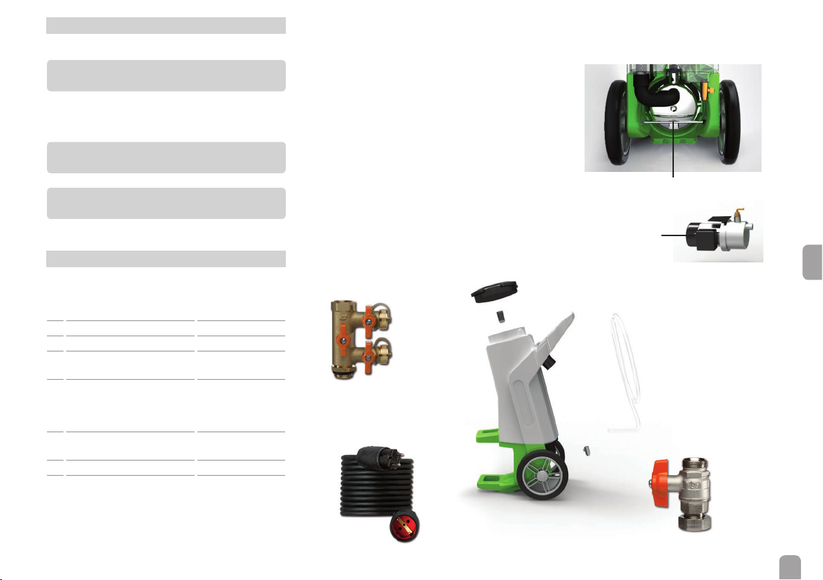
• Integrierter Schmutzfilter auf der Saugseite
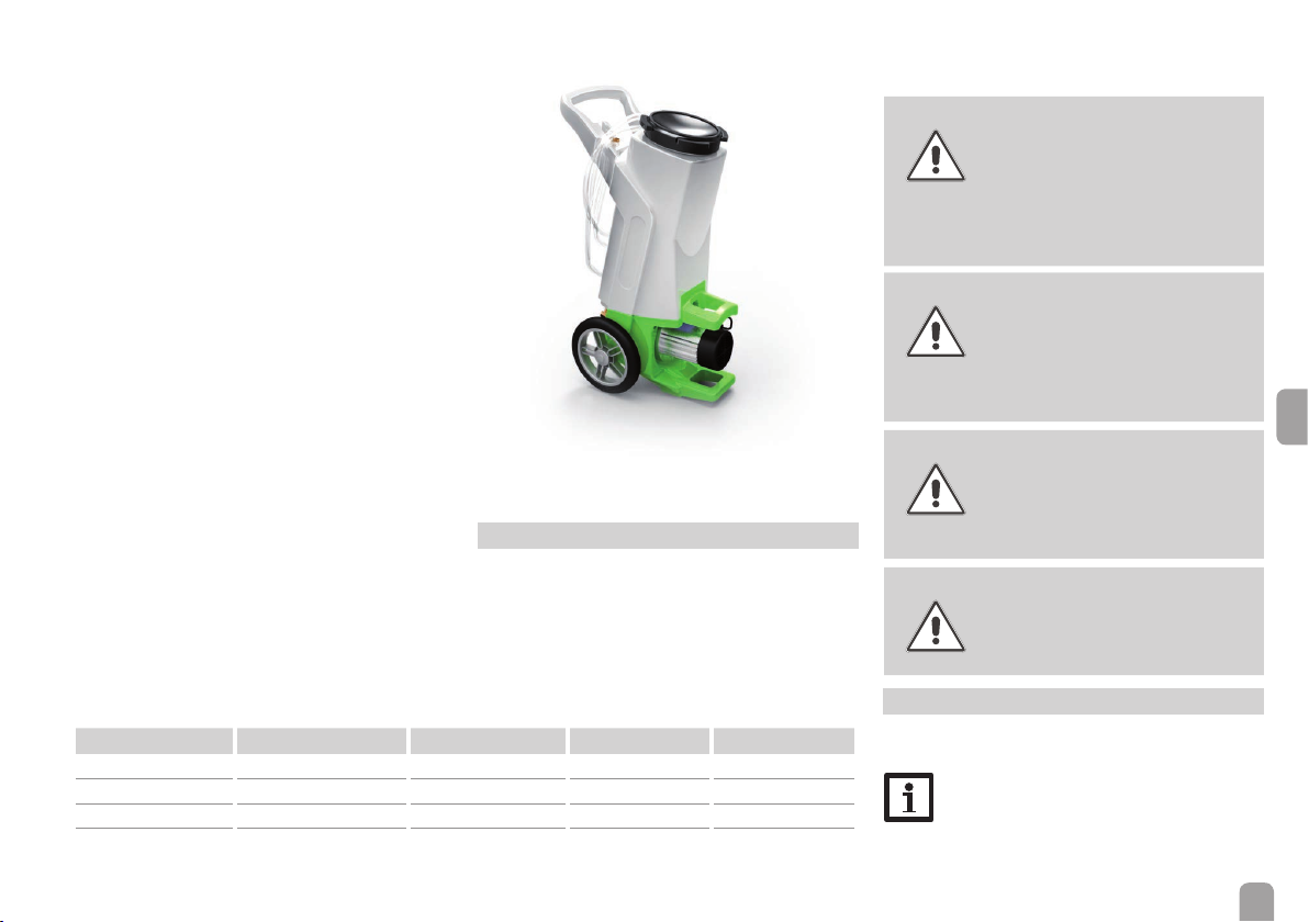
Technische Daten
Abmessungen: H×B×T = 1000 ×400 ×530 mm
Gewicht: 21kg
Tank: 30 Liter, PE, mit Schmutzfilter
Förderstrom: 5-47 l/min
Förderhöhe: 42m
Pumpenleistung: 550 W (230V~, 50 Hz)
Pumpendruck: 4,2bar
Schlauchanschlüsse: ¾" Überwurfmutter
Entleerungshahn: ½"
Medium: Wasser, Glykolgemische,
Reinigungsflüssigkeiten für Solaranlagen
Mediumtemperatur: max. 65°C
Version DE UK 230V~UK 115 V~ US
Artikelnummer 280 010 90 280 010 93 280 011 93 280 010 97
Pumpe 230V~ / 50 Hz 230V~ / 50 Hz 115V~ / 60 Hz 115V~/ 60 Hz
Anschluss Schutzkontakt-Dose UK-Stecker UK-Stecker US-Stecker
Pumpendruck 4,2 bar 4,2 bar 4,2 (3*) bar 4,2 bar
* bei Betrieb mit 50 Hz
Der Anwender hat sich in jedem Fall selbst davon zu
überzeugen,ob die Spül- und Befüllstation SBS 2000 für
das zu verwendende Medium eingesetzt werden kann.
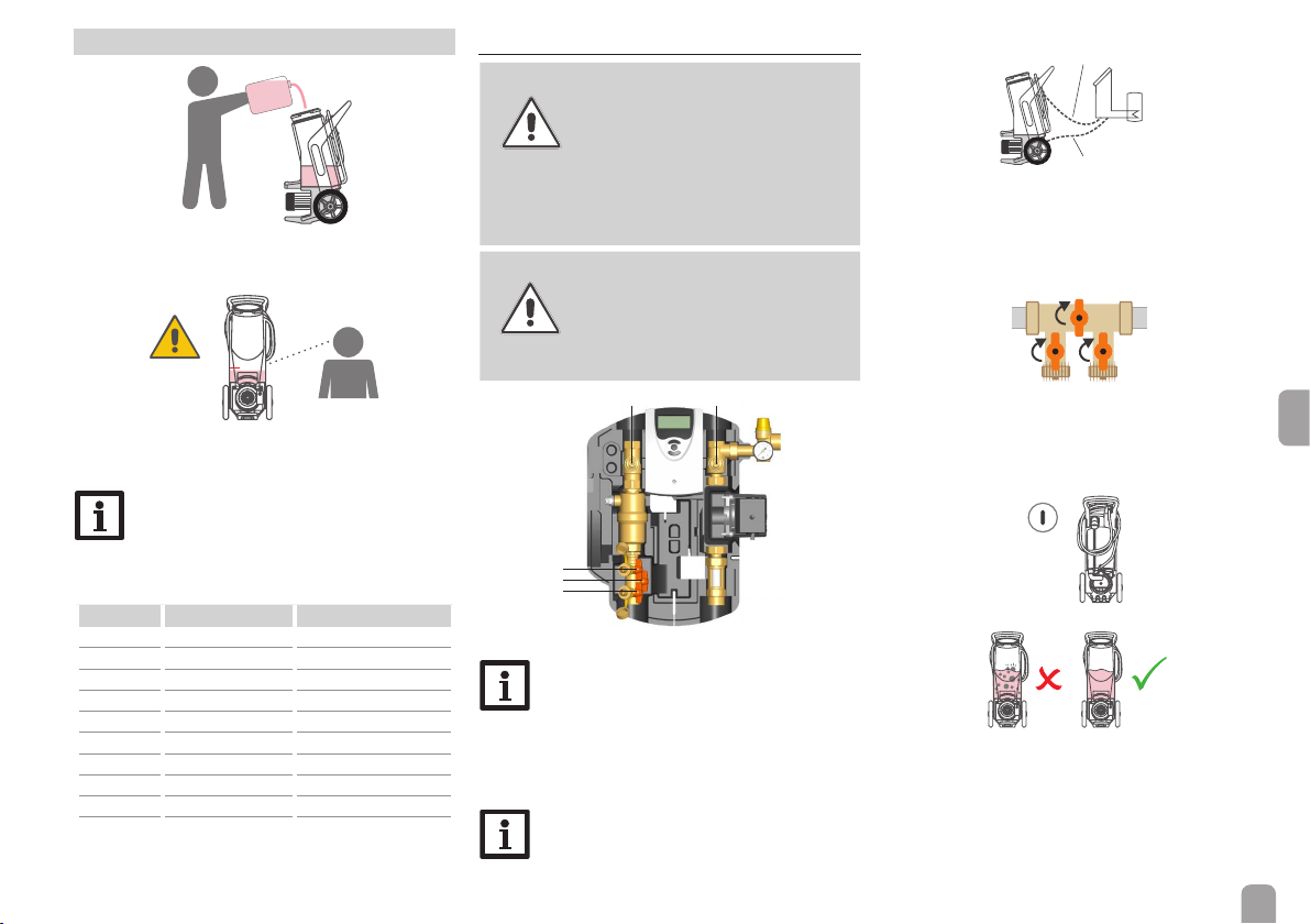
WARNUNG! Lebensgefahr durch Explosion
oderVerpuffung!
Das Fördern von Stoffen mit einem
Flammpunkt unter 55°C kann zu Ex-
plosionen oderVerpuffungen führen.
ÎDie Station nicht mit Benzin,
Lösungsmitteln oder anderen
explosiven Stoffen betreiben!
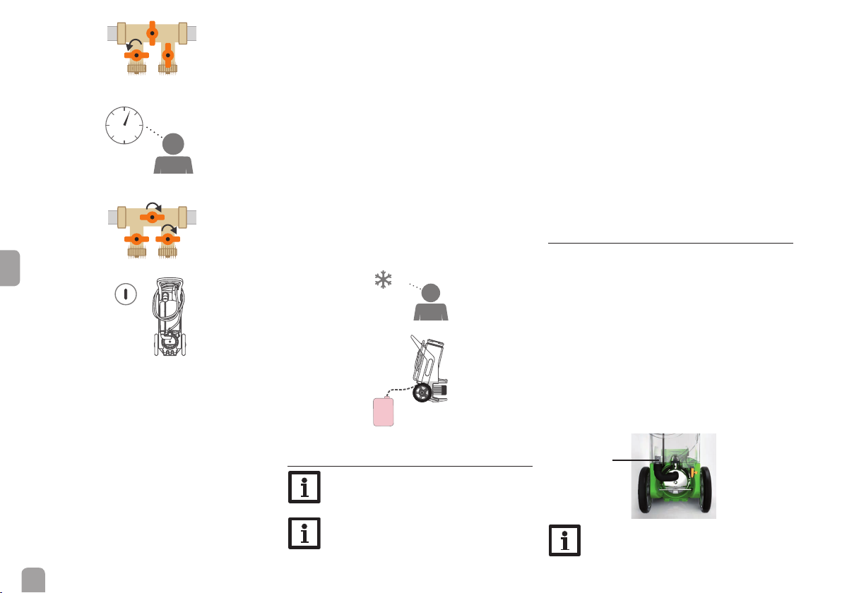
ACHTUNG! Sachschaden durch Druckstöße!
Strömt das Wärmeträgermedium in
stark erhitzte, leere Kollektoren, kann
es zu Druckstößen kommen.
ÎDie Anlage nicht bei starker
Einstrahlung spülen oder be-
füllen!
ACHTUNG! Sachschaden durch Überhitzung!
Der Motor der Pumpe kann während
des Betriebes bis zu 70 °C erreichen.
ÎDarauf achten, dass die Luft-
zufuhr des Motors zur Selbst-
kühlung nicht blockiert ist!
WARNUNG! Verbrennungsgefahr durch
Überhitzung!
Der Motor der Pumpe kann während
des Betriebes bis zu 70 °C erreichen.
ÎErhitzte Pumpe nicht berühren!
2 Elektrischer Anschluss
Die Anschlussleitung muss mindestens einen Quer-
schnitt von 1,5 mm² haben.
Hinweis
Zur eigenen Sicherheit die Spül- und Befüll-
station nur an einem Stromkreis betreiben,
der mit einem Fehlerstromschutzschalter
abgesichert ist.
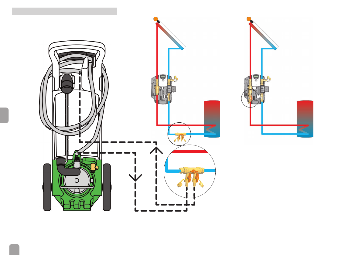
1 Allgemeine Hinweise
Die Spül- und Befüllstation SBS 2000 ist nur für Was-
ser, Wasser-Glykol-Gemische und Reinigungsflüssig-
keiten für Solar- und Heizungsanlagen geeignet. Das
Medium darf keine Abriebstoffe enthalten, kann aber
verschmutzt sein.Verschmutzungen aus dem System
werden von dem saugseitig im Tank integrierten
Schmutzfilter zurückgehalten.