LD/LJ Side Wall Vent Kit Instructions
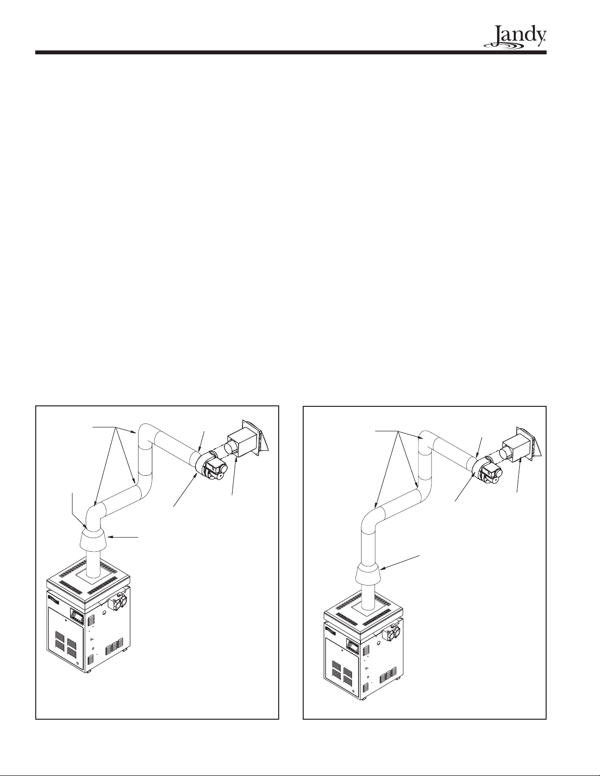
4. The vent pipe diameter is determined by the size
of the heater. The full length of the vent pipe must
be the diameter as stated in Table 1 on page 1. On
heater sizes 125, 175, 325, and 400, use the "bell"
reducer, enclosed in the kit to attach the vent pipe
to the power venter blower. On heater size 250,
use the "bell" reducer to attach the vent pipe to the
draft hood.
5. Horizontal sections of the vent pipe must have a
minimum 1/4 inch vertical rise per foot of pipe,
sloping upward, away from the heater.
6. There must not be any other appliance connected
to this venting system.
3. Electrical Connections
Please refer to the Tjernlund Products, Inc. "Side
Wall Vent Systems" installation manual for safety
information and detailed information on the Tjernlund
products.
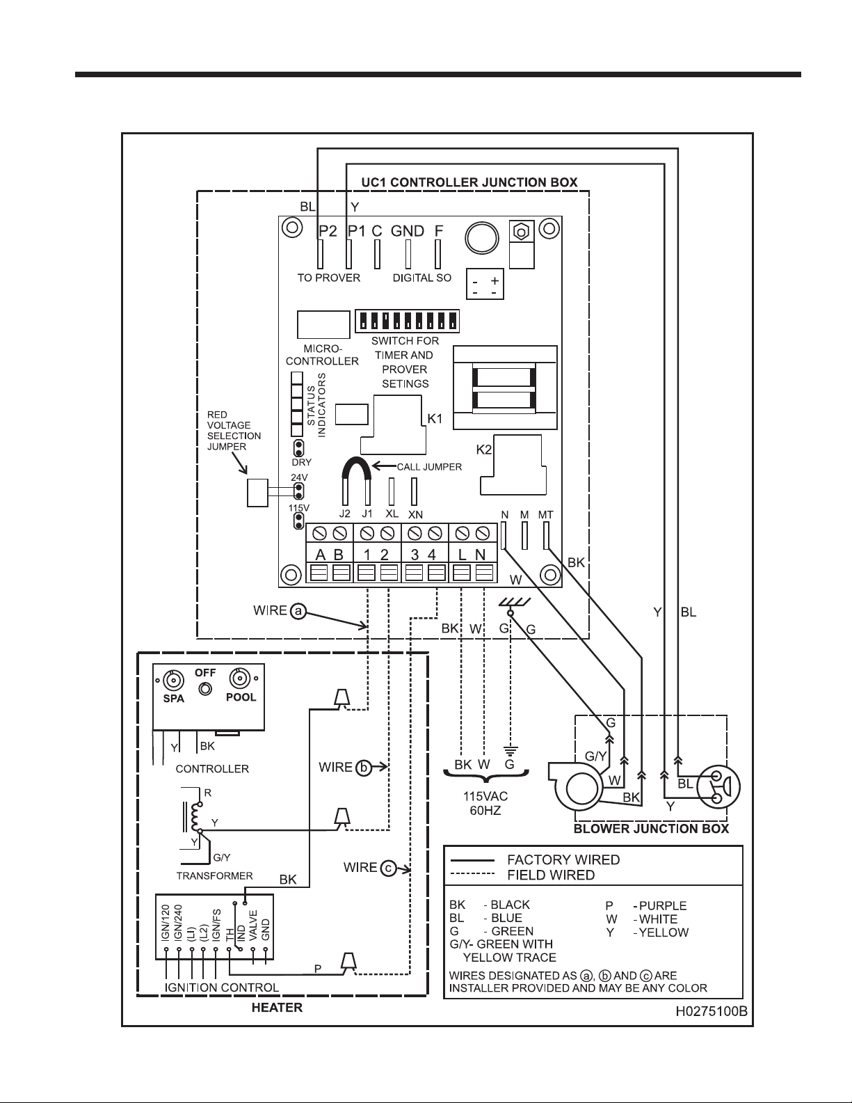
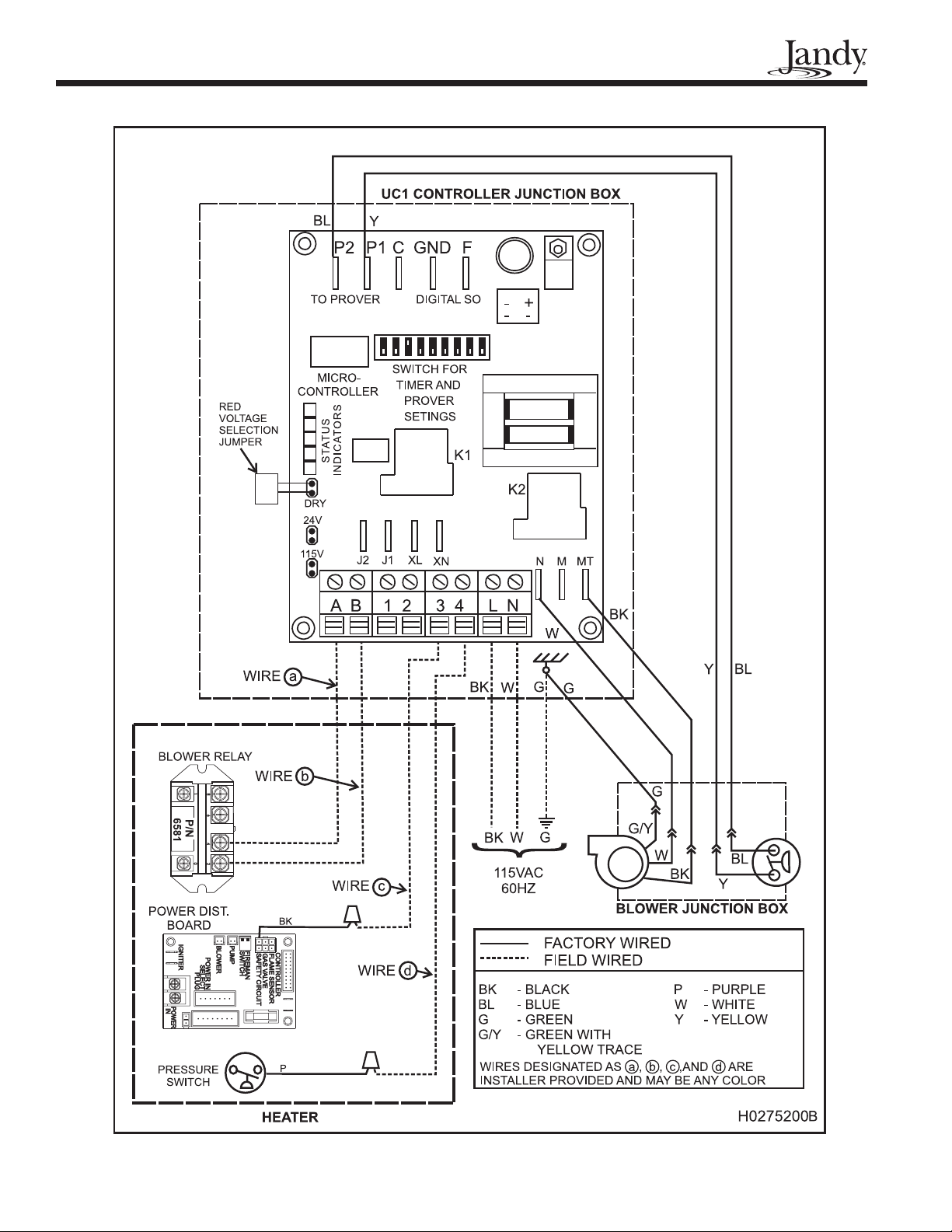
The following instructions are specic to the wir-
ing and operation of the kit's blower and control panel
with the LD and LJ heaters. These instructions and the
wiring diagrams must be followed exactly in order for
the system to operate safely and efciently.
WARNING
SHOCK HAZARD!
3.1 Preparing The Heater
The internal 24 volt heater wiring must be slightly
modied to incorporate the side wall vent controller into
the safety circuit.
Section 3.1.1 describes the steps to modify the
model LD heater.
Section 3.1.2 describes the steps to modify the
model LJ heater.
3.1.1. Modify the Model LD Heater
Wiring
1. Turn off the main breaker to the circuit that sup-
plies the heater with power.
2. Remove the heater door.
3. Locate the common terminal on the transformer.
There will be a yellow wire with a "piggy back"
terminal attached to the transformer and a green
wire with a yellow trace connected to the "piggy
back" terminal (refer to the heater's wiring di-
agram).
4. Disconnect the green wire with a yellow trace
from the "piggy back" terminal.
5. Plug the double male connector, included in the
kit, onto the "piggy back" terminal.
6. Reconnect the green wire with a yellow trace to
one (1) terminal of the double male connector.
7. Connect the yellow wire, supplied in the kit, to the
other terminal on the double male connector and
strip 1/2" of insulation off of the end of the wire.
8. Remove the black wire from the "TH" terminal of
the ignition control.
9. Cut the terminal off of the black wire and strip the
insulation back 1/2" from the end.
10. Connect the purple wire, supplied in the kit, to the
"TH" terminal of the ignition control.
3.1.2. Modify the Model LJ Heater
Wiring
1. Turn off the main breaker to the circuit that sup-
plies the heater with power. If the pump is con-
nected to the heater's internal time clock, turn off
the breaker to the circuit that supplies power to the
pump.
2. Remove the heater door.
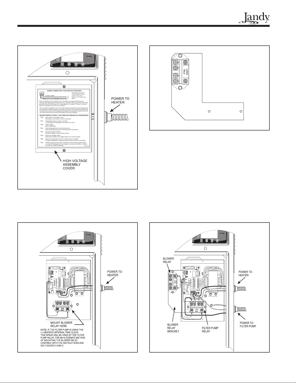
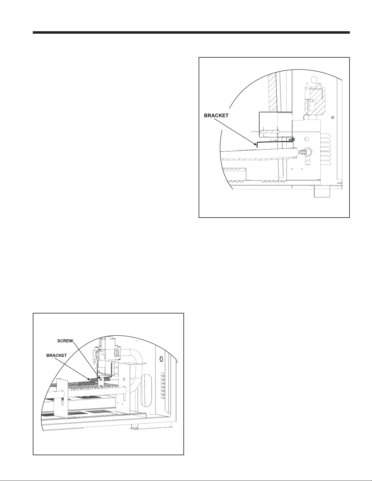
3. Remove the cover from the high voltage assembly
(see Figure 3).
4. Mount the blower relay to the back panel of the
high voltage assembly (see Figure 4). If the lter
pump is connected to the heater's internal time
clock, the pump relay will already be mounted in
this position. To mount the blower relay, do the
following:
- Mount the blower relay to the relay bracket,
included in the kit, using the provided screws,
as shown in Figure 5, if a standard time clock
is controlling the lter pump.
- If a lter pump relay is controlling the lter
pump, remove the pump relay from the back
panel of the high voltage assembly. Do not dis-
connect any of the wires attached to the relay.