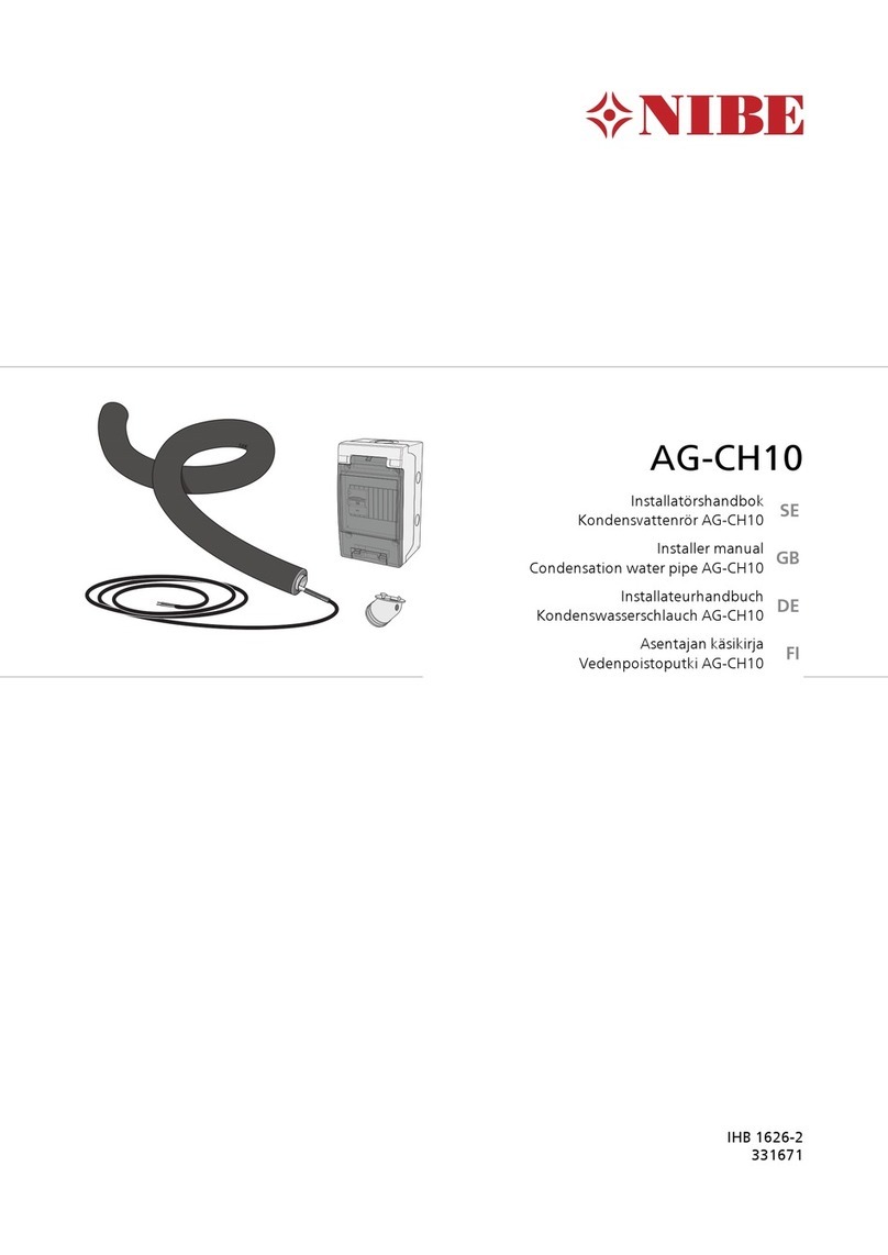
Nibe ETS 121 User manual

MAV GB 0451-2 611260
ETS 12 / 121
R
INSTALLATION INSTRUCTIONS
ETS 12 / 121
Electrical addition
Heatpumps are not usually dimensioned to handle the
entire heat output requirement. Some form of addi-
tional output is necessary on cold days.
ETS 12 / 121 consists of an immersion heater with a
contactor set comprising of a thermostat and tempera-
ture limiter. The contactor set is designed for installa-
tion in the electrical connection area on FIGHTER
1110/1115/1120.
This accessory makes it possible to use the Extra hot
water function when a water heater is connected via
the accessory VST 11.
FIGHTER 1110/1115: The function is activated from
menu 14, see the Installation and Maintenance
Instruction.
FIGHTER 1120: The function is activated from menu
9.2.13.2, see the Installation and Maintenance
Instruction.
ETS 12 for 3-phase. Part no 089 399
ETS 121 for 1-phase. Part no 089 419
General
ETS 12 / 121
Components
LEK
67
20
10253
24
23
141 142
145
143
144
140
LEK
3 Operating thermostat, standby mode
10 Contactor, immersion heater step 1
20 Contactor plate with components
23 Protective housing, immersion heater
24 Immersion heater
25 Temperature limiter
67 Contactor, immersion heater step 2
140 Cover
141 Seal
142 Knob
143 Cable ties, 4
144 Screws, 4
145 Assembly screws, 4
List of components
NOTE!
The electrical installation must be
carried out by a qualified electrician.
The electrical installation and wiring
must conform to current regulations.
NOTE!
Reset the temperature limiter (25).
It may have tripped during transport.
In the event of a fault on the heat pump's control or
collector circuit you can move the switch (8) to stand-
by mode. Only the heating medium pump and electri-
cal step 2 are activated in this mode. Heat for hot tap
water can not be produced as VST 11 is not active.
The flow temperature is controlled by the thermostat
(3). This needs to be set at an appropriate tempera-
ture depending on the type of heating system and out-
door temperature.
NOTE! When the operating option “fixed condensing”
is selected on FIGHTER 1110/1115, the heating medi-
um pump is not operational.
Standby mode

ETS 12 / 121
■Before the work is started, ensure the heat pump
has been disconnected from the mains.
■Open the covers/plates in the following order:
Lower service cover, lower, right-hand side plate,
upper, angled service cover, open out the electri-
cal panel plate and loosen the top cover.
■Drain the heating medium side according to the
instructions in the Installation and Maintenance
Instruction.
ALoosen the existing blinding plate and fit the seal
(141) and immersion heater (24) in the immer-
sion heater tube.
BCentre the protective housing (23) around the
immersion heater and secure to the frame using
the 2 assembly screws (145).
CPosition the contactor set (20) on the right-hand
side of the electrical connection area, align the
screw holes and secure the plate using the 4
screws (144) and press on the knob (142).
Connect the wires with the connector marked
-X211. The wire marked -X210b is not used.
DConnect the white control wire (marked 13) on
switch (8) terminal 3A.
EConnect the 3-way edge board connector to the
relay board (29) in the intended position, marked
15, 16, 17, see the figure.
FConnect the contactor set's supply wires
(4 x 2.5 mm) to terminal (22) in the electrical con-
nection area.
GRoute the immersion heater wires (7 x 2.5 mm)
through the cable entry to the immersion heater.
HRoute the temperature limiter and thermostat
capillaries through the cable entry and position
them in the pocket tube on the immersion heater.
Make sure the capillaries are insulated and can-
not come into contact with live connections. It is
important that thermostat and overheating pro-
tection capillaries are placed in the immersion
heater's pocket tube in the right order to get the
best function and performance from the immer-
sion heater. See the figure below.
I. Connect the immersion heater according to the
chosen output configuration, see the Connecting
the immersion heater section.
J. Secure the wires and capillaries in the immersion
heater housing using a cable tie (143). Other
cable ties are used as necessary for attractive
and safe cable routing.
K. Screw the cover (140) on the immersion heater
housing using 2 assembly screws (145) and refit
all the covers/plates.
■
Fill the heating medium side with water.
■
Vent the system.
■
Switch on the power.
Installation and connection FIGHTER 1110/1115
LEK
D
K
8
A
I
B
JHG
CE
29
22
F
Termostat
Överhettningsskydd
Overheating protection
Thermostat

ETS 12 / 121
Wiring diagram FIGHTER 1110/1115
Anslutes i -X22
032
033
034
035
LEK
+2-2
1
R
0
-X9
-K10
-X22
-B3 -D25
-K69
-K67
Connected to the relay board
Connected to -X22
Immersion heater Immersion heater
step 2 Immersion heater
step 1

ETS 12 / 121
■Before the work is started, ensure the heat pump
has been disconnected from the mains.
■Open the covers/plates in the following order:
Lower service cover, lower, right-hand side plate,
upper, angled service cover, open out the electri-
cal panel plate and loosen the top cover.
■Drain the heating medium side according to the
instructions in the Installation and Maintenance
Instruction.
A. Loosen the existing blinding plate and fit the seal
(141) and immersion heater (24) in the immer-
sion heater tube.
BCentre the immersion heater housing (23) around
the immersion heater and secure to the frame
using the 2 assembly screws (145).
CPosition the contactor set (20) on the right-hand
side of the electrical connection area, align the
screw holes and secure the plate using the 4
screws (144) and press on the knob (142).
Connect the wire with the connector marked
-X210b.
The wire marked X211 is not used.
DRemove the tow jumpers between -X6:11–12
and -X6:13–14.
Connect:
wire 021 to X6:11
wire 022 to X6:13
wire 023 to K69:13
wire 024 to X6:12
wire 025 to X6:14
wire 026 to K69:14
wire 027 to X6:15
EConnect the contactor set's supply wires
(4 x 2.5 mm) to terminal -X9.
FRoute the immersion heater wires (7 x 2.5 mm)
through the cable entry to the immersion heater.
GRoute the temperature limiter and thermostat
capillaries through the cable entry and position
them in the pocket tube on the immersion heater.
Make sure the capillaries are insulated and can-
not come into contact with live connections. It is
important that thermostat and overheating pro-
tection capillaries are placed in the immersion
heater's pocket tube in the right order to get the
best function and performance from the immer-
sion heater. See the figure below.
HConnect the immersion heater according to the
chosen output configuration, see the Connecting
the immersion heater section.
ISecure the wires and capillaries in the immersion
heater housing using a cable tie (143). Other
cable ties are used as necessary for attractive
and safe cable routing.
JScrew the cover (140) on the immersion heater
housing using 2 assembly screws (145) and refit
all the covers/plates.
■
Fill the heating medium side with water.
■
Vent the system.
■
Switch on the power.
Installation and connection FIGHTER 1120
Termostat
Överhettningsskydd
LEK
J
A
H
B
IGF
C
DE
The figure shows the 3-phase, FIGHTER 1120 model
Overheating protection
Thermostat

ETS 12 / 121
Wiring diagram FIGHTER 1120 ETS 12 (3-phase)
Anslutes i -X6 och -K69
032
033
034
021
022
023
026
027
024
025
032
033
034
035
-X9
-K10
-X6
-B3
-D25
-K69
-K67
Connected to -X9 Connected to -X9 Connected to -X6 and -K69
Immersion
heater
Immersion
heater
Immersion heater
step 2 Immersion heater
step 1

ETS 12 / 121
Anslutes i -X6 och -K69
032
033
034
035
037
021
022
023
026
027
024
025
Wiring diagram FIGHTER 1120 ETS 121 (1-phase)
-K69 -X9
-K10
-K67
-X6
-B3
-D25
Connected to -X9 Connected to -X6 and -K69
Immersion
heater Immersion heater
step 2 Immersion heater
step 1

ETS 12 / 121
2 White connection white ––white white white
4 Red connection brown brown –brown brown brown
6 Red connection brown brown –brown brown brown
8 White connection blue blue blue blue –blue
10 Red connection ––––brown blue
No.
3 x 400 V 9 kW 3 x 400 V 6 kW 3 x 400 V 3 kW
3 x 400 V 3 x 230 V 230 V
1 White connection white –white white white white
3 White connection white ––white –white
5 Red connection brown white brown brown –brown
7 White connection blue blue blue blue white blue
9 Red connection –
FIGHTER 1110/1115 FIGHTER 1120
=jumper
Current step 2 6 kW 8.7 A 4 kW 15 A 4 kW 18 A
Voltage
3 x 400 V + N 3 x 230 V 230 V 1-phase
ETS 12 ETS 12 ETS 121
Current steps 1 and 2 9 kW 13 A 6 kW 22.5 A 6 kW 27 A
Current step 1 3 kW 4.3 A 2 kW 7.5 A 2 kW 9 A
See the table for the different connection options for each
voltage.
The blue wire 037 is only used for 230 V 1-phase. On other
models the wire is removed from the wires harness.
The blue wire 036 is not connected on the 3 x 230 V model.
Technical specifications
Connecting the immersion heater

NIBE AB
SWEDEN
R
Tel: +46 - (0)433 - 73 000
Fax: +46 - (0)433 - 73 190
E-mail: [email protected]
www.nibe.com
Box 14
Järnvägsgatan 40
SE-285 21 MARKARYD
PL
DE
NL
DK
FI
Vølund Varmeteknik
Filial af NIBE AB
Brogårdsvej 7, 6920 Videbæk
Tel: 97 17 20 33
Fax: 97 17 29 33
E-mail: [email protected]
www.volundvt.dk
Haato Varaajat
NIBE AB:n sivuliike
Valimotie 27, 01510 Vantaa
Puh:09 - 274 697 0
Fax: 09 - 274 697 40
E-mail: [email protected]
www.haato.fi
NIBE Systemtechnik GmbH
Am Reiherpfahl 3
29223 Celle
Tel: 05141/7546-0
Fax: 05141/7546-99
E-mail: [email protected]
www.nibe.de
NIBE Energietechniek B.V.
Steenpad 11
4797 SG WILLEMSTAD
Tel: 0168 477722
Fax: 0168 476998
E-mail: [email protected]
www.nibeboilers.nl
NIBE-BIAWAR Sp. z o. o.
Aleja Jana Paw
ła II 57
15-703 BIA
ŁYSTOK
Tel: 085 662 84 90
Fax: 085 662 84 14
E-mail: [email protected]
www. iawar.com.pl
CZ NIBE CZ
V Zavetri 1478/6
CZ-170 00 Prague 7
Tel: 0266 791 796
Fax: 0266 791 796
E-mail: [email protected]
www.nibe.com
This manual suits for next models
1
Table of contents
Other Nibe Heat Pump Accessories manuals