AERMEC RePuro 100 User manual

IREPPY - 1404 - 4238051_01
HEAT RECOVERY UNIT - Technical Manual
high
eciency
ErP
2015
RePuro 100
RePuro 170
RePuro 250
RePuro 350
RePuro 450
RePuro 550
RePuro 650

AERMEC S.p.A. reserves the right at any moment to make any modifications considered necessary to improve our products and is not obliged to add
these modifications to machines that have already been fabricated, delivered or are under construction.
Dear Customer,
Thank you for choosing an AERMEC product. This product is the result of many years of experience
and in-depth research, and it is built using top quality material and advanced technologies.
Moreover, the CE mark guarantees that the appliances fully comply with the requirements of the
European Directives in terms of safety. The quality levels are constantly monitored, and AERMEC
products are synonymous with Safety, Quality, and Reliability.
Product data may be subject to modifications deemed necessary for improving the product with-
out obligation to give prior notice.
Thank you again.
AERMEC S.p.A

Aermec RePuro is the innovave soluon which oers air renewal with 90% eciency and its purica-
on at the same me through Plasmacluster, this device is a standard equipment on each unit
Aware of the importance of air renewal and puricaon, AERMEC RePuro, has been designed in order to
oer the best performances compared to the products currently available on the market, we can high-
light:
1 – Very high heat recovery eciency
Caused by the countercurrent air/air exhanger
The “countercurrent exchanger” technology permits to reach recovery eciency greater than 90%. Con-
sequently the fresh air gets in at a very similar temperature to that of the room: this performance is ab-
solutely greater than a tradional recovery mixed ow unit.
2 – Minimized energy consumpon
Caused by inverter driven fans
The employ of high eciency inverter technology, in line with commission regulaon (EU) No 327/2011,
grants the maximum exibility in air ow and avalable stac pressure regulaon for each system. The fans
eciency is already in line with the stated values in commission regulaon of 2015.
3 – High quality of the air
Because of Plasmacluster device
Plasmacluster technology is based on the physical principle of ions generaon which aract the water
molecules of the air creang aggregates called “clusters”. The “clusters” completely surround the danger-
ous microparcles of the room, and consequentely removing their harmful eects on people. This creates
a further ltraon eect compared to the standard mechanical lters currently available on the market.
4 – High availability of accessories
The best tecnology of RePuro involves an high availability of accessories so this unit can be perfectly inte-
grated in each kind of system.
5 – User interface
simple in the ulizaon and elegant shape
All RePuro units are complete with a wall hung user interface with capacive touch LCD screen coming
from the aesthecally pleasing VMF-E4 which won the “Good Design” award in 2010.
6 – Only one system for each comfort need
through the integraon of RePuro with Aermec VMF system
Compared to a stand alone tradional mechanical venlaon system, RePuro has been designed to be
part of (oppure to be integrated in) the VMF system network as the component dedicated to the air re-
newal and puricaon.
Starng from today Aermec oers a complete system which allows to control each need of:
- Heang
- Condioning
- Domesc hot water management
- Air renewal and puricaon
granng the overall best system eciency beyond an opmal result ensured by an unique manufactorer.
ErP
2015
high
eciency

DECLARATION OF CONFORMITY
We, the undersigned, declare under our exclusive responsibility that the assembly dened
as:
NAME RePuro
TYPE HEAT RECOVERY UNIT
MODELS Field Code Description
1..6 RePuro Name of unit
7..9 350 Unit size (250-350-450-550-650)
10 R Pre-heating element
To which this declaration refers and conforms with the following harmonised standards:
CEI EN 60335-2-80
CEI EN 60335-2-65
IEC EN 55014-1
IEC EN 55014-2
IEC EN 61000-6-1
IEC EN 61000-6-3
IEC EN 62233
Satisfy the essential requirements of the following directives:
- Electromagnetic compatibility directive
2004/108/EC
- Low voltage directive
LVD 2006/95/EC
Bevilacqua 01/04/2014
Commercial Director
Luigi Zucchi
AERMEC S.p.A.
37040 Bevilacqua (VR) Italy–Via Roma, 996
Tel. (+39) 0442 633111
Telefax 0442 93730–(+39) 0442 93566
RePuro 100
RePuro 170
RePuro 250
RePuro 350
RePuro 450
RePuro 550
RePuro 650

INDEX
1. GENERAL WARNINGS..................................................................................................................................................... 5
1.1. Conservaon of documentaon............................................................................................................................................. 5
1.2. Safety warnings and installaon standards ........................................................................................................................... 5
2 PRODUCT IDENTIFICATION............................................................................................................................................. 5
3. INFORMATION ............................................................................................................................................................... 6
3.1. Handling ................................................................................................................................................................................. 6
3.2. Transport ............................................................................................................................................................................... 6
3.3. Checks on recepon............................................................................................................................................................... 6
3.4. Included.................................................................................................................................................................................. 6
3.5. Electrical power cable ............................................................................................................................................................ 6
3.6. Connecng cable for the wired control panel........................................................................................................................ 6
3.7. Installaon.............................................................................................................................................................................. 6
4. INTRODUCTION TO RESIDENTIAL VENTILATION AND THE AERMEC RePuro TECHNICAL SOLUTION.................................... 7
4.1. INDOOR AIR QUALITY (IAQ).................................................................................................................................................... 7
4.2. Plasmacluster ........................................................................................................................................................................ 12
4.3. Reference standard for the venlaon of buildings............................................................................................................... 13
4.4. Eciency of the heat recovery unit ....................................................................................................................................... 14
5 DESCRIPTION .................................................................................................................................................................... 15
6 VERSIONS AVAILABLE........................................................................................................................................................ 15
7 MAIN COMPONENTS ........................................................................................................................................................ 16
7.1 Component descripon........................................................................................................................................................... 16
8 TECHNICAL DATA............................................................................................................................................................... 17
9 OPERATING LIMITS ........................................................................................................................................................... 17
10. PERFORMANCES .......................................................................................................................................................... 18
10.1. Performances RePuro100..................................................................................................................................................... 18
10.2. Performances RePuro170..................................................................................................................................................... 20
10.3. Performances RePuro250..................................................................................................................................................... 22
10.4. Performances RePuro350..................................................................................................................................................... 24
10.5. Performances RePuro450..................................................................................................................................................... 26
10.6. Performances RePuro550..................................................................................................................................................... 28
10.7. Performances RePuro650..................................................................................................................................................... 30
10.7. Plenum performances PLS350W - PLSM350W - PLS650W - PLSM650W with water coil .................................................... 32
11. ACCESSORIES ................................................................................................................................................................. 33
11.1. Accessories compability table ............................................................................................................................................ 33
11.2. Accessories descripon........................................................................................................................................................ 34
12. DIMENSIONS ................................................................................................................................................................. 37
13. INSTALLATION ................................................................................................................................................................ 38
13.1. Preliminary operaons......................................................................................................................................................... 38
13.2. Ceiling installaon ................................................................................................................................................................ 40
13.3. Wall installaon.................................................................................................................................................................... 41
13.4. Floor installaon................................................................................................................................................................... 42
13.5. Electrical connecons........................................................................................................................................................... 43
13.6. Connecng the air duct to the unit ...................................................................................................................................... 44
13.7. Condensate discharge .......................................................................................................................................................... 45
14. WIRED PANEL ................................................................................................................................................................ 46
14.1. Installaon of the wired panel ............................................................................................................................................. 46
14.2. Compability between the wired control panel and the electrical wall boxes .................................................................... 47
15. ELECTRICAL SCHEMATICS ............................................................................................................................................... 48
16. ORDINARY MAINTENANCE............................................................................................................................................. 50
16.1. Mechanical checks.................................................................................................................................................................................... 50

6IREPPY - 1404 - 4238051_01
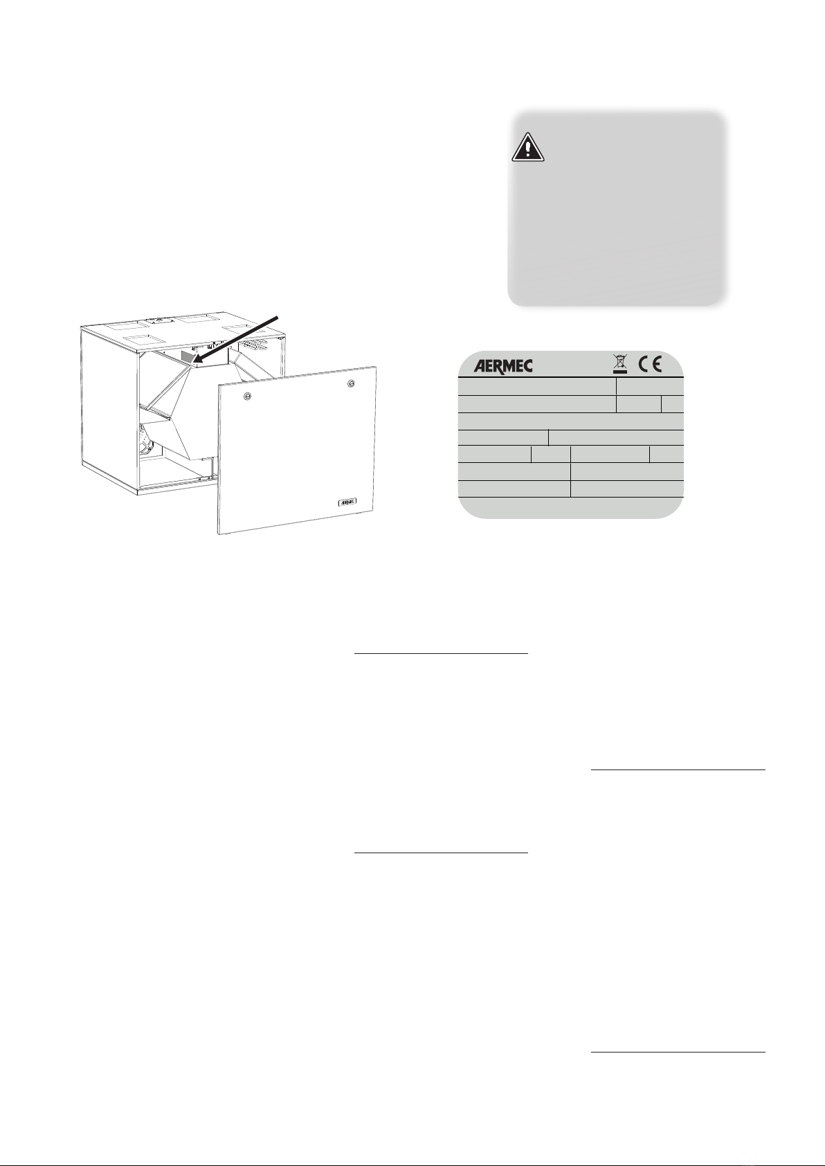
The AERMEC RePuro units are manu-
factured in accordance with recog-
nised technical standards and safety
regulations. They are designed for the
renewal and treatment of ambient
air, and they must be used for the
purpose for which they are intended
and their performance character-
istics. All contractual and extra-
contractual liabilities causing damage
to persons, animals or objects or
through errors of installation, control
or maintenance or from improper use
are excluded by the Company. Any
uses not expressly indicated in this
manual are not permitted.
1.1. CONSERVATION OF DOCU
MENTATION
Consign the instructions with all the
complementary documentation to
the user of the accessory who will as-
sume responsibility for the conserva-
tion of the instructions so that these
are always available in case of need.
Carefully read this document. The
execution of all the works must be
carried out by qualified personnel, in
accordance with the national regula-
tions.
It must be installed in such a way
to make maintenance and/or repair
functions possible.
Do not modify or tamper with the
accessory as this may cause danger
for which the manufacturer will not
accept any responsibility for damages
caused. The warranty is voided if the
above instructions are not followed.
1.2. SAFETY WARNING AND
INSTALLATION STANDARDS
−The unit must be installed by a
competent and qualified technician,
and in accordance with the legislation
applicable in the country of installa-
tion.
AERMEC assumes no responsibil-
ity for damage caused by failure to
observe these instructions.
−Instructions essential for the proper
installation of the equipment are
shown here. The final touches to all
the operations are however left to
the experience of the installation en-
gineer in accordance with the specific
needs.
−Before commencing any works
it is necessary to CAREFULLY READ
THE INSTRUCTIONS AND MINIMISE
ANY RISKS BY TAKING APPROPRIATE
SAFETY PRECAUTIONS.
−All relevant personnel must be
made aware of the procedures and
possible risks that may arise at the
time of installation of the unit.
−The unit must be installed in such a
way as to make easy ordinary main-
tenance (filter cleaning) and special
maintenance as well as access to the
heat exchanger.
−WARNING! : It is absolutely
forbidden the operate the unit
without the 4 nozzles connected to
the ducting system.
−DANGER : The fan is located
immediately beneath the nozzles. It is
absolutely forbidden to insert hands
or objects. Power the unit only after
the 4 nozzles are connected to the
ducting system.
−ATTENTION: In order to
protect the unit against short circuits,
mount a magnet circuit breaker
omnipolar switch on the power
supply line. In order to avoid any
danger due to the accidental rearm-
ing of the thermal cut-out device, this
appliance must not be powered with
an external switching device, such as
a timer, or be connected to a circuit
that is regularly powered or discon-
nected from the service
−ATTENTION: The appliance
can be used by children over the age
of 8 and by people with reduced
physical, sensory or mental capabili-
ties or without experience or neces-
sary knowledge, as long as they are
supervised or have been instructed
on the safe use. Of the appliance and
on the understanding of the dangers
inherent to it. Children must not play
with the appliance. The cleaning and
maintenance to be carried out by the
user must not be carried out by
children without supervision.
OPERATING LIMITS of the unit:
Maximum air temperature: 50°C
Maximum differential pressure be-
tween the two fluids: 2000 Pa
Versions without pre-heating
element
Minimum outdoor air temperature:
-10°C *
Versions with pre-heating element
(R)
Minimum outdoor air temperature :
-15°C *
* With external air temperature <
0°C the microprocessor controller in-
tervenes to reduce the risk of forma-
tion of frost within the heat recovery
unit. If the outside air temperature is
less than the limits, the microproces-
sor controller stops the unit opera-
tion.
1. GENERAL WARNINGS

7
IREPPY - 1404 - 4238051_01
example of technical label:
MODELLO
MODEL
RePuro350R
VERSIONE
VERSION 00
Numero di serie
Serial Number
Peso
Weight IPxx
20kg
YYMMLLPPPPPPXXXX
Tensione nominale
Rated Voltage 230V Frequenza Nominale
Rated Frequency 50Hz
0000000_00
Potenza Assorbita Nominale
Rated Power Input 180W
Numero Commessa
Purchase Order 000000
Corrente Assorbita Nominale
Rated Current Input 1.6A
Potenza Assorbita Nominale con resistenza
Rated Power Input with electric heater 180W
Potenza Assorbita Nominale con resistenza
Rated Power Input with electric heater 1.6A
WARNING: The tampering,
removal or absence of the
identification label ren-
ders difficult any operation
of installation or mainte-
nance.
technical label
RePuro350R
The RePuro air heat recovery units are
identified through:
−PACKING LABEL
that records the product identifica-
tion data.
−TECHNICAL LABEL
2. PRODUCT IDENTIFICATION
3. INFORMATION
During the installation, maintenance
and cleaning phases provide ade-
quate personal protective equipment
(PPE).
The unit must not be used for stor-
age or spare parts. Any use not
expressly detailed in this manual can
create danger and is forbidden. The
unit must be installed by a compe-
tent technician in compliance with
regulations in force in the country
of installation with respect for the
minimum clearance spaces required
for maintenance.
Before installation check that the
unit has not suffered damage during
transport:
• operation of a damaged unit can
be dangerous
• the installation base must be
capable of supporting the weight
of the unit.
Note:
For all future reference and com-
munication with AERMEC S.p.A. it is
necessary to state the serial number.
3.1. HANDLING
WARNING!
During the handling phase provide
adequate personal protective equip-
ment (PPE).
Before the installation and use it is
recommended to completely remove
all packaging from the unit and com-
ponents supplied loose.
3.2. TRANSPORT
For safe transport refer to the weight
information shown on the nameplate
applied to every unit.
In all cases transport has to be done
with the following precautions:
• the unit and any accessory must
not be subjected to violent
shocks to avoid affecting the
integrity of the structure and the
internal components
• the unit and any accessories
must be appropriately secured
on the transport device with
ropes or any means that prevent
movement
• during transport the unit and any
accessories must be protected
from suffering any shocks
• during transport the load must
be protected from the weather.
3.3. CHECKS ON RECEIPT
On receipt of the unit it is necessary
to carry out an initial visual check to
ensure:
• all components are present
• no damage to the unit.
In case damage is found this must be
recorded on the accompanying docu-
mentation.
The checks to be made are the fol-
lowing:
• check the integrity of the unit
• check the integrity of the casing.
3.4. LOOSE ITEMS
The components for the installation
of the RePuro unit are found within

8IREPPY - 1404 - 4238051_01
the unit.
Before starting with the installation it
is necessary to open the heat exchang-
er unit panel and remove the material
contained within:
- 1 Control panel
- 4 Ducting connections
- 4 Isolating covers for the connections
- 1 Condensate discharge connection
- Screws necessary to fix components
- 1 Filter G2
- 1 Filter G4.
3.5. ELECTRICAL POWER CABLE
The unit is provided with the electrical
power cable and plug.
The electrical power cable is 2 metres
long.
If the power supply cable is damaged,
it must be replaced with a new cable
of adequate section. Have the repair
made by “Qualified personnel”, in
order to prevent any risk.
Do not repair damaged cables.
For the electric power supply, use
integral cables with suitable section
for the load.
3.6. WIRED PANEL CONNECTING
CABLE
The unit is provided with a cable 6 me-
tres long for connection to the wired
panel. However, if a longer cable is
required (not provided) then this must
have the same characteristics as the
cable supplied loose (screened 4 core
cable)and must have a MAXIMUM
length of 30 metres.
3.7. INSTALLATION
It is recommended to carefully follow
the information provided in the fol-
lowing paragraphs for the installation.
The paragraphs are arranged chrono-
logically in order to simplify each
phase of installation.
Retrieve the documents (manuals and dec-
larations of conformity) and the compo-
nents required to complete installation from
inside the unit.
Place of installation
• Install the units indoors.
• Precautions must be taken during
installation to avoid gas backflow
from the gas discharge flue or from
other fuel appliances.
Before installation, check the technical
spaces required:
• for installation;
• for the set up of the flow and expul-
sion ducts;
• for draining condensation, a space
of at least 200 mm for the siphon
must be provided;
• for cleaning the filters;
• for cleaning the exchanger.
CEILING INSTALLATION
RePuro100-170
Use the 4 brackets supplied to install
the unit to the ceiling.
Install the brackets before making the
unit connections.
WALL INSTALLATION
RePuro100-170
Use the 4 brackets supplied to install
the unit to the wall.
Install the brackets before making the
unit connections.
RePuro250-350-450-550-650
Use the installation plate for wall fix-
ing.
The unit is supplied with the plate ap-
plied on the rear side.
Attention: the position of the mount-
ing plate upon receipt of the unit does
not correspond to the final installation
position (see drawings).
FLOOR INSTALLATION
RePuro250-350-450-550-650
Use the appropriate accessories to
install the unit on the floor:
- use anti-vibration mounts (AVM) for
installations with the condensate drain
siphon recessed in the floor. Install the
feet before making the unit connec-
tions.
- use the support brackets with anti-
vibration mounts (SSR) for installations
with the condensate drain siphon
between the unit and the floor. Install
the brackets before making the unit
connections.

9
IREPPY - 1404 - 4238051_01
Pollutant Correlated symptoms
Benzene
Produced from external trac or from proximity to pet-
rol staons, chemical industries, and steelworks. With
garages joined to dwellings it can move towards internal
rooms. It can be released from cooking and heang sys-
tems.
Elevated concentraons can cause death in a maer
of hours. Exposure by connuous inhalaon at lower
levels mainly aects the blood producing illnesses of
anaemia, lymphopenia and leukemia.
Carbon Monoxide
(CO)
Is found in external air and is produced by the bad
combuson of endothermic engines. In internal
spaces it can be caused by an incorrect installaon,
a defect, or poor maintenance of cooking systems or
heang systems burning fossil fuels.
High concentraons (>80%) cause death by cardiac
arrest. Exposure by connuous inhalaon at lower
levels can cause memory loss, psycho-emove al-
teraons, asthma, and heart failure.
Formaldehyde
Mainly produced within internal environments. It is
generated by tobacco smoke, heang systems, burn-
ing candles or incense. It is also produced by construc-
on materials (resins applied on wooden furniture and
insulang materials) and is frequently used in cleaning
products (it is a strong bactericide).
Provokes irritaons of the upper respiratory system.
In more serious forms it causes carcinomas.
Nitrogen dioxide
(NO2)
Derives from combuson processes (the main pro-
ducer is vehicular trac). Within internal environ-
ments this substance is produced from tobacco
smoke and combuson (from any combusble);
combuson being the worst and major producer of
this gas.
Can cause eczema, throat and ear infecons and
leads to increased allergen sensivity in children.
In adults it can contribute to the increase of respira-
tory symptoms (such as asthma).
Polycyclic aromac
hydrocarbon (PAH)
Produced from combuson at high temperature.
Comes from vehicular trac in the external air. Inter-
nally it is produced from cigaree smoke, re places,
cooking systems, smoke from candles and incense.
Is a carcinogenic substance.
Radon
Is naturally produced from the radioacvity of certain
rocks. There can be traces in some construcon mate-
rials and in the water.
Is a carcinogenic substance (lung cancer).
Trichloroethylene
Is produced in industrial environments (cooling sys-
tems), dry cleaners, print works (prinng ink), paints,
texle prinng. In internal environments it comes
from printers, fax and photocopy machines, as well
as cleaning products and furniture paint.
Is a carcinogenic substance (liver and lung tumours);
other symptoms involve deformity of the eyes and
heart.
Tetrachloroethylene
Is a solvent agent used in industrial applicaons
(steelworks, texle industries, inks and cleaning
products). In internal environments it can be pro-
duced from adhesives, perfumes, stain removers,
fabric nish, water repellents, wood detergents and
detergents for vehicles.
In various concentraons aack eyes, kidneys, liver,
lungs and mucous membranes of the skin, causing
renal, liver and reproducve systems failure. A cor-
relaon has also been shown with oesophageal and
cervical cancer.
4. INTRODUCTION TO RESIDENTIAL VENTILATION AND THE AERMEC RePuro TECHNICAL SOLUTION
4.1.
In terms of preventing health risks deriv-
ing from ambient factors it is only in recent
years that more attention has been paid to
internal air pollution; the quality of the en-
vironments in dwellings or schools, techni-
cally defined as indoor.
When we think about the air that we
breathe in a residence in a traditional ur-
ban centre, compared to that outdoors,
we conclude that the outdoor air quality
is worse.
This is not always the case and the oppo-
site could be true.
On average the internal air of a domestic
environment is more polluted than that
outdoors.
Due to infiltration caused by the opening
of doors and windows the air breathed in-
doors is the same as outdoors.
In practice the result becomes:
air in house
=
external air + internal pollutants
Recently constructed dwellings are de-
signed to minimise the infiltration of air,
and as a consequence the pollutants pro-
duced internally remain there.
Internal and external pollutants are of this
nature:
- chemical
- biological
- physical
The following table shows the main pollut-
ants, where they come from and what ef-
fects they provoke or cause (source: World
Health Organizaon – (WHO) GUIDELINES
FOR INDOOR AIR QUALITY – 2010).

10 IREPPY - 1404 - 4238051_01
The chemical-physical pollutants, as
shown above, are not the only elements
that contribute to the pollution of the in-
door environment.
There are also biological pollutants (mites,
bacteria, virus, moulds, dirt from animal
origin) that provoke or cause chronic res-
piratory symptoms. A collection of studies
on this subject is published in DAMPNESS
AND MOULD from 2009 produced by the
WHO.
Living in residences with high humidity
levels increases the risks of illnesses.
The table summarises the symptoms in
percentages that occur to people living in
environments with polluted air.
Symptom Percentage increase in symptoms
Upper respiratory related symptoms 52%
Cough 50%
Hoarseness 44%
Asthma already diagnosed 50%
Asthma not diagnosed 33%
Development of asthma 30%
People who live in “unhealthy” buildings
can be subject to asthma and allergies; the
risk of contracting rare diseases line chron-
ic rhinitis, allergic alveolitis, or hypersensi-
tivity pneumonitis are increased.
Internal environmental pollution has con-
sequences, not only on health, but also
on society. All the diseases shown here
constitute a significant cost for the health
system. The Italian Ministry of Health pro-
duced in 1999 a study on the impact these
pollutants have on the population and the
direct health costs.
Bad air quality certainly has effect on
human productivity, both at work and
school. We all have experiences of reduced
concentration in closed environments
without ventilation.

11
IREPPY - 1404 - 4238051_01
4.2. PLASMACLUSTER
Each RePuro unit is supplied as standard
with a Plasmacluster filter.
Plasmacluster is a system of ion genera-
tion suitable for the purification of internal
spaces. It works by deactivating bacteria
and viruses present in the air.
It is not an electrostatic filter, having an air
purification mechanism. Using a genera-
tor it decomposes certain water molecules
present in the air (humidity) by electrical
discharges, creating a flow of hydrogen and
oxygen ions.
Molecules or atoms electrically charged
are called ions. The process of electron
gain or loss is called ionisation. Ionisation
is normally carried out by the application
of high energy to the atoms, in the form of
electrical potential or radiation. . An ion-
ised gas is called “plasma”.
The positive and negative ions thus gener-
ated are supplied to the space, transport-
ed by the treated air flow, and attract the
water molecules present creating “clus-
ters” of molecules.
As the process continuous these clusters
collect around a pollutant agent (for ex-
ample, a virus). At this point positive and
negative ions unite to form the hydroxyl
radical OH- which removes the hydrogen
from the surrounded virus, necessary for
its survival.
From the hydroxyl OH-acquiring the hy-
drogen, water is produced which is intro-
duced to the space; the virus is damaged
by the reaction and therefore eradicated.
The Plasmacluster purification process is
completed.

12 IREPPY - 1404 - 4238051_01
Compared to electrostatic filter the Plas-
macluster technology has four main ad-
vantages:
• In electrostatic filters the air is forced
through a metallic filter where the elec-
trostatic precipitation is produced. The
polluting particles are violently attracted
to the metal plates that make up the filter
by strong electric fields, where they then
remain energetically attached. All the pol-
lutants thus captured remain strongly at-
tached to the filter plates, and with the
use of the de-purifier, get progressively
dirtier until a visible layer of inert material
forms over time. At this point the dirt is re-
moved from the filter.
• The filter becomes a pressure drop as
it visibly gets dirty during operation, and
requires periodic cleaning as required by
its appearance. From this it can be easily
understood that over time there is a pro-
gressive degradation in filter efficiency of
such devices.
• Another important advantage is in the
electrical voltage which is around 10-12kV
for electrostatic filters, whilst for the Plas-
macluster system it is 100-200V. Some
electrostatic filters must have regulation
systems to stabilise the high voltages and
short circuit protection systems on the
high voltage of the filter itself.
• Traditional electrostatic filters, unlike the
Plasmacluster system, only operate well in
constant operating conditions, are physi-
cally large, normally require a pre-filter to
avoid overloading the filter and frequent
maintenance.
Plasmacluster works mainly on four fronts,
described here.
The following show the results on several viruses which are sadly well known.
Virus Reference Environment test
volume
environment to Plasma-
cluster
Percentage of virus
H5N1 Avian u virus 1 cubic metre 10 minutes 99.9%
H1N1 Seasonal u 1 cubic metre 25 minutes 99.7%
Feline coronavirus Infecve virus that at-
tacks cats
1 cubic metre 35 minutes 99.7%
SARS Virus that causes the
symptome known as
SARS
Test tank 3.3 seconds 73.4%
To see the action of Plasmacluster on vi-
ruses here are two electron microscope
images. The left shows the virus (Feline
coronavirus) before exposure and the
right the same virus inactivated from the
action of the ioniser.
Inactivation of viruses
As described above, the ions freed by
Plasmacluster adhere to the surfaces of
microbes removing hydrogen from the pro-
tein that they are made from: this process
makes them inactive.
Numerous studies carried out by prestig-
ious European and Japanese universities
have been conducted on this matter.
Virus destroyed
Virus

13
IREPPY - 1404 - 4238051_01
Mould
As with viruses and bacteria, the ions
freed by Plasmacluster work on the pro-
liferation of the mould in closed spaces. .
A test conducted by Japanese researchers
has shown how the exposure of a normal
PVC window to the action of the Plasma-
cluster filter has allowed the reduction,
compared to a similar unit, of around 25%
of the mould that was created over a pe-
riod of 5 days.
This also has a positive effect on the mould
carried in suspension in the air. According
to a test carried out by the Ishikawa Health
Service Association, the Plasmacluster op-
erating in a room of 13m2has drastically
reduced the content in the period of about
three hours.
Elimination of odours
It has been shown that the use of Plas-
macluster facilitates the elimination of
odours created in spaces.
A test was made analysing a sample cloth
infused with cigarette smoke. In normal
conditions the odour drops to impercep-
tible levels in 4 hours, but with the use of
Plasmacluster this time is reduced to one
hour.
Development of allergens
Several studies have shown how the ion-
iser has inhibited the protein of which the
allergens are made up from, generated
from dust mites faeces, dead dust mites,
which are one of the main sources of al-
lergies.
Plasmacluster works both by inhibiting
any mites present and on their prolifera-
tion.
Germicidal lamp
RePuro can be combined with accessories
from the plenum series PLS and PLSM;
these accessories can be supplied with the
germicidal lamp which integrates the ac-
tion of the Plasmacluster for a better pu-
rity of air supplied to the room.
This exclusive device with germicidal lamp
with mercury vapour sterilises the air with
a microbiological effectiveness of 99.999%
inactivating all microorganisms Gram - and
Gram + .
The germicidal lamp is located in the supply
air to ensure a higher cleaning of the duct-
ing, preventing the formation of mould and
ensuring the maximum level of efficiency
and reduction of cleaning requirements.
Such a device for the sterilisation of air
makes RePuro indispensable in rooms that
require the maximum level of hygiene such
as hospitals, dental studios, medical and/
or veterinary surgeries, analysis laborato-
ries, pharmaceutical laboratories, waiting
rooms, beauty centres, residences, offices,
and public places.
From 50 to 100% of total
From 0 to 25% of total
Dust formaon
exposed to the eect of
Plasmacluster
Spontaneous
dust formaon
Spontaneous dust
with Plasmacluster
(3.000 ions/cm3)
Axis of lament growth
Percentage remaining (%)
Time (minutes)
with
Plasmacluster
without
Plasmacluster
Dust mites
faeces
Dead dust mites
Density of allergens due to
dust mites (pg/cm3)
Increase
Inial Value
Normal
reducon aer 2
hours
Plasmacluster
Odour intensity
Allergen
growth
block

14 IREPPY - 1404 - 4238051_01
Category Air renewal rate Living room
bedroom
Extract ow rate
l/s per m2
(a)
Vol/h l/s per person ( b) l/s per m2
(a)
Kitchen
l/s
Bathroom
l/s
Toilee
l/s
I0,49 0,7 10 1,4 28 20 14
II 0,42 0,6 7 1,0 20 15 10
III 0,35 0,5 4 0,6 14 10 7
4.3. REFERENCE STANDARD FOR THE
VENTILATION OF RESIDENTIAL BUILD
INGS
The concept of air ventilation for confine
spaces is taken into consideration by sev-
eral standards.
The Standard EN 12792:2003 (Ventilation
for buildings – symbols terminology and
graphical symbols) defines two concepts:
Aeration: meaning natural ventilation by
opening a window.
Ventilation: meaning the extraction and sup-
ply of air to a space. It is interesting to note
that the standard talks about “designing” for
ventilation.
The talks about the
energy efficiency of buildings and defines
it as the quantity of energy effectively con-
sumed or that is anticipated to be required
to satisfy the various needs connected to
the standard use of a building, including
amongst others: heating of water, cool-
ing, ventilation and lighting. The directive
underlines to take account of the general
climatic conditions of the internal spaces in
order to avoid any negative effects due to
inadequate ventilation.
Note that it talks about ventilation and not
aeration, and even the standards that deal
with the renewal of air always use the term
renewal and not aeration: opening and
closing windows is not considered an effec-
tive system for the renewal of air.
How and when to renew is considered in
EN 15251:2007 (Criteria for the indoor envi-
ronment including thermal, indoor air quality,
light and noise), which combines aspects of air
quality within buildings with energy aspects.
Having said that the air quality in buildings
depend on numerous parameters (number of
people, activities carried out, humidity, smoke,
emissions from furniture and construction ma-
terials, etc.), it is an essential fact that ventila-
tion must be continuous, and acceptable that
the air renewal rate requirement is variable
depending on whether the space is occupied
or not.
If not occupied the air renewal rate is be-
tween 0.05 and 0.1l/s, per m2.
If the space is occupied the same stand-
ard defines different air renewal classes:
the higher the renewal rate the higher the
building class.
I: High requirement level, recommended
for spaces occupied by very sensitive and
fragile people with special needs, such as
the handicapped, the sick, very small chil-
dren and the elderly.
II: Normal requirement level, to be used for
new constructions and renovations.
III: Acceptable, moderate requirement lev-
el, to be sued for existing buildings.
IV: Values outside of the criteria for the cat-
egories above. This category might only be
accepted for a limited part of the year.
(a): The air renewal ratel expressed in l/s per m2and Vol/h (hourly volume) coincide with a ceiling height of 2.5 m.
(b): The number of occupants of a dwelling can be evaluated from the number of bedrooms.
If there are any national or local requirements these are used.
Suppose we have to design an air renewal
system for an apartment of S=100m2with
room heights of h = 2.5m.
As recommended by the standard EN
15251:2007, if we want to ensure a catego-
ry III, the air renewal rate must be:
S × h × 0.5 = 100 × 2.5 × 0.5 = 125m3/h
if the space is occupied. But if the space is
not occupied the air renewal rate becomes:
S × 0.05 = 100 × 0.1 = 10l/s = 36m3/h

15
IREPPY - 1404 - 4238051_01
4.4. EXAMPLE OF ENERGY SAVING
CALCULATION
The following shows an analysis made on
the energy advantage for the heat recov-
ery solution used in a residential building
located in 2468 DD climatic zone (EN ISO
15927-6:2007).
The analysis takes into consideration a por-
tion of a twin apartment, with useful sur-
face area of 150m2. The dwelling consists of
two stacked floors.
The chart shows the winter primary ener-
gy use (EPi) expressed in kWh/(m2x year)
of the same building.
In the three cases the EPi value of the en-
closure is equal at 37,578 kWh/(m2per
year), whilst the dierence in the columns
is due to the air renewal variaon in re-
newal rate and how it is achieved.
0
10
20
30
40
50
60
37,578
With renewal rate
0.3Vol/h
without recovery
EPi kWh/(m2per year)
With renewal rate 0.5Vol/h
recovery eciency 50%
With renewal rate 0.5Vol/h
recovery eciency 90%
In the absence of controlled mechanical
venlaon the air ow renewal rate of
spaces is xed at 0.3Vol/h: in such a case
the EPi index of the building is esmated as
55,978kWh/(m2per year).
Such air renewal is not sucient to have
a good space air quality which must be at
least 0.5vol/h according to EN 15251. Such
a renewal rate can be obtained with a me-
chanical venlaon system with eciency
of 50%: in which case the EPi becomes
52,928 kWh/(m2per year).
If instead a high eciency mechanical ven-
laon system like RePuro is used, this re-
quirement becomes 40,522kWh/(m2 per
year).
In the rst case (aeraon) of the building is
in class B for energy performance for win-
ter condioning and the air quality is low.
In the last case with high eciency heat re-
covery not only is the minimum air renewal
in accordance with standard EN 15251, but
the building increases its energy perfor-
mance for winter condioning.
For the soluon with mechanical venla-
on (CMV) with 50% eciency the EPi
increases considerably with increasing air
renewal rates, but with the RePuro solu-
on the value also increases, but consider-
ably less.
0
20
40
60
80
1
00
0,3 Vol/h
1 Vol/h 0,7 Vol/h 0,5 Vol/h
EPi kWh/(m2per year)
Aeraon or natural
venlaon
With MV eciency 50%
With MV
eciency 90%
* S/V = Relaonship between the outer surface of the volume heated to unheated spaces (surface area loss) and the gross volume of the heated parts of
the building heated
Useful surface area m2150
Surface loss area m2315
Gross volume heated m3450
S/V * 1/m 0,7
Climatic zone (EN ISO 15927-6:2007) Degree-Days (DD) 2468
EPi limit 2010 kWh/(m2per year) 82,245
Window transmiance W/(m2x K) 1,513
Wall transmiance W/(m2x K) 0,255
Floor transmiance W/(m2x K) 0,185
Ceiling transmiance W/(m2x K) 0,310

16 IREPPY - 1404 - 4238051_01
4.5. HEAT RECOVERY ENERGY EFFI
CIENCY
Generally heat exchanger energy ef-
ciency is dened as the relaonship
between actual energy exchanged be-
tween the two air masses (extract air
and supply air) and the ideal energy:
η = Qreal
Qideal
If the air flow rates are equal (supply and
extract), the efficiency becomes the ratio
between temperature difference:
η = Qreal
Qideal
η = tsupply air - texternal air
tinternal air - texternal air
For example, if:
texternal air = -5°C
tinternal air = 20°C
The supply air temperature is determined
once the efficiency of the heat recovery
unit is known.
Then:
tsupply air =
= η × (tinternal air - texternal air) + texternal air
So if η = 0.9 with the values shown you
have:
t supply air = 0,9 × (20+5)-5 = 17.5°C
The directive is split into two steps: the
first in 2013 and a more restrictive one in
2015.
In RePuro, not only do the fans greater
than 125W already respect the 2015 lim-
its, but even those of lower capacity do.
Certification ErP 2015
ErP
2015
With the implementation of the Kyoto
Protocol the European Union has fixed an
objective to reduce by 20% energy con-
sumptions, by 20% CO2emission and to in-
crease by 20% the renewal energy sources
by 2020.
These measures, known as 20-20-20 also
involves the ventilation industry.
The Product Directive 2009 (known as ErP
2015, Energy related Products Directive),
has established that for all types of fans,
with capacities between 0.125kW and
500kW, which operate as “stand alone” or
as components within a system, must have
a minimum efficiency depending on the
type of fan and its capacity. This efficiency
is not given only to the motor but for the
assembly of motor + controller (for exam-
ple, inverter) + Fan.

17
IREPPY - 1404 - 4238051_01
6. VERSIONS AVAILABLE
Ceiling mounted
RePuro100 RePuro100
RePuro170 RePuro170
RePuro250 RePuro250
RePuro350 RePuro350
RePuro450 RePuro450
RePuro550 RePuro550
RePuro650 RePuro650
Versions (R) with electric pre-heater (500W) for connuous operaon in cold climates down to -15°C
RePuro250R RePuro250R
RePuro350R RePuro350R
RePuro450R RePuro450R
RePuro550R RePuro550R
RePuro650R RePuro650R
(*) With the use of appropriate accessories
RePuro is an innovave counter-ow heat
recovery system which ensures the correct
renewal of air to indoor environments.
Through the use of heat exchangers of
high eciency up to 90%, RePuro allows
the supply air temperature to be close to
the space temperature, reducing the en-
ergy costs normally associated with tra-
dional fresh air systems or mechanical
venlaon only.
PLASMACLUSTER ionising filter capable of
destroying pollutants by decomposing
their molecules.
The result is in the air: finally we can
breathe clean air, ionised and free from
bad smells.
5. DESCRIPTION

18 IREPPY - 1404 - 4238051_01
• FRAMEWORK - STRUCTURE
• HEAT EXCHANGER
• FAN ASSEMBLY
• FILTER SECTION
• CONDENSATE DRAIN TRAY
• PLASMACLUSTER FILTER
• FREE COOLING DAMPER
• BYPASS DAMPER
• ELECTRIC PRE-HEATER (only for RePuro
R)
• ELECTRICAL CONNECTIONS
• WIRED CONTROL PANEL
• FRAMEWORK - STRUCTURE
Self supporting panels in galvanised sheet
steel with internal insulation.
The unit is protected against frost in cli-
mates with temperatures down to -10°C.
Suitable for wall or ceiling mounng (Re-
Puro 100-170)
Suitable for wall mounng with standard
supplied plate and oor mounng with
dedicated accessories (RePuro 250-350-
450-550-650).
Steel flanges for connection to air ducts.
• HEAT EXCHANGER
High efficiency heat exchanger even
exceeding 90% (EN 308), of hexagonal
shape to increase the heat exchange area.
Easily removed for cleaning or replace-
ment.
• FAN ASSEMBLY
Centrifugal fans directly coupled to high
efficiency EC “Brushless” motors with var-
iable speed (ErP2015).
Control of nominal air flow in 20 steps
from 0 to 100%.
Anti-freeze by air flow modulation: during
winter operation the heat recovery unit
modulates the air flow supplied to the
room to prevent the formation of frost on
the heat exchanger with extended operat-
ing limit down to -10 °C external air tem-
perature. The air flow modulation is linked
to the external air sensor.
• FILTER SECTION
Filter removable for cleaning or replace-
ment.
Standard filter G2 efficiency class on the
extract air.
Standard filter G4 efficiency class on the
supply air.
Possibility to replace the standard G4 effi-
ciency filter with a F7 efficiency class filter
(accessory).
• CONDENSATE DRAIN TRAY
Drain tray supplied with outlets for con-
nection to the condensate drainage sys-
tem.
• PLASMACLUSTER FILTER
Ioniser filter PLASMACLUSTER as stand-
ard.
(See the dedicated section for further de-
tails)
• BYPASS FREE COOLING DAMPER
Standard for RePuro 250-350-450-550-
650.
Automatic bypass for operation in Free
cooling during mid-season.
If the space temperature is greater than
the setpoint (Tset ambient), and the ex-
ternal air temperature (Ta.e.) is below this
value, the heat recovery unit achieves the
desired condition by supplying the exter-
nal air without any heat recovery (bypass
free cooling).
• BYPASS ANTI-FREEZE DAMPER
Standard for RePuro 450-550-650
In the heat recovery units Repuro 450
- 550 and 650 there is the bypass anti-
freeze section.
This systems allows internal mixing of
some of the room return air with the ex-
ternal air supply air flow.
This function is active when the external
air temperature is below 10°C and greater
than 0°C.
To ensure the flow of warm air across the
damper the system modulates the extract
fan air flow.
• ELECTRIC PRE-HEATER (only for per
RePuro_R)
Standard for RePuro 250R-350R-450R-
550R-650R.
The heat recovery units RePuro_R include
and electric element pre-heater and can
integrate the anti-freeze operation by air
flow modulation with the activation of the
electric heater in relation to the external
air temperature.
The pre-heater element can only be ena-
bled during the AUX operating mode (see
the user manual for further details).
With the electric pre-heater element
to operating range is extended down to
-15°C.
• ELECTRICAL CONNECTIONS
Microprocessor control board that can be
interfaced with the VMF system complete
with:
- power supply cable 2m long with plug,
- connector for the control panel,
- terminal block for RS485 connecon.
- terminal block for TTL connecon,
- terminal block for connecon to remote
contact and window contact,
- terminal block for connecon to the wa-
ter temperature sensor, external air tem-
perature sensor, and supply air tempera-
ture sensor.
• WIRED CONTROL PANEL
Control of the unit with a wired control
panel of innovative design, extremely
slim, allowing the control of functions
with a capacitive touch keypad and with
LCD display.
After a power failure the unit restarts
with the settings already programmed on
the wired panel.
Activation of the electric element in the
versions RePuro_R.
Front panel of light grey colour PANTONE
COOL GRAY 1C.
Standard supplied cable of 6 metres
length.
7. MAIN COMPONENTS
7.1. COMPONENT DESCRIPTION

19
IREPPY - 1404 - 4238051_01
RePuro 100 170 250
250R
350
350R
450
450R
550
550R
650
650R
m3/h 100 170 250 350 450 550 650
Pa 85 20 195 133 100 120 70
Winter recovery eciency % 94,4 91,2 91,9 89,4 90,3 88,6 87
Recovered heang capacity W 957 1573 2329 3171 4118 4940 5734
Winter recovery eciency (*) % 90,6 85,3 86,3 82,2 83,7 81 78,4
Recovered heang capacity (*) W 601 963 1433 1910 2500 2957 3386
Summer recovery eciency % 90,6 85,3 86,4 82,2 83,7 81 78,5
Recovered cooling capacity W 180 289 430 573 750 887 1015
m3/h 75 125 150 200 300 350 450
Pa 135 110 331 376 210 300 270
Winter recovery eciency % 95,7 93,2 94,8 93,3 93 92,1 90,3
Recovered heang capacity W 728 1181 1441 1891 2830 3267 4118
Winter recovery eciency (*) % 92,7 88,6 91,1 88,6 88,2 86,6 83,7
Recovered heang capacity (*) W 462 735 908 1177 1758 2014 2500
Summer recovery eciency % 92,7 88,6 91,2 88,7 88,3 86,7 83,7
Recovered cooling capacity W 138 220 272 353 527 604 750
m3/h 50 75 75 100 150 175 200
Pa 185 210 426 526 310 430 485
Winter recovery eciency % 97 95,7 97,2 96,4 96,2 95,7 95,1
Recovered heang capacity W 492 728 739 977 1463 1697 1928
Winter recovery eciency (*) % 95 92,7 95,3 93,9 93,6 92,7 91,7
Recovered heang capacity (*) W 315 462 475 623 932 1077 1218
Summer recovery eciency % 95 92,7 95,3 93,9 93,6 92,7 91,7
Recovered cooling capacity W 95 138 142 187 280 323 365
Weight kg 25 25 48 48 55 55 55
Maximum power input W 45 65 160 180 220 280 360
Pre-heater element power input (ver-
sions R)W 500 500 500 500 500 500 500
Power supply V ~ Hz 230 ~ 50
* Winter recovery
condion
EN 308
Extract air 25°C D.B.
27% R.H.
Supply air 5°C D.B.
50% R.H.
Winter recovery
condion
Extract air 20°C D.B.
50% R.H.
Supply air -10°C D.B.
80% R.H.
The available pressure may change
from the nominal due to the an-freeze
control
Summer recovery
condion
Extract air 26°C D.B.
50% R.H.
Supply air 32°C D.B.
50% R.H.
(1) (2) Performances refer to condions different to the nominal conditions
Model
RePuro100 - RePuro170
RePuro250 - RePuro350
RePuro450 - RePuro550 - RePuro650
-10°C +50°C
RePuro250R - RePuro350R
RePuro450R - RePuro550R - RePuro650R -15°C +50°C
8. TECHNICAL DATA
9. OPERATING LIMITS

20 IREPPY - 1404 - 4238051_01
0
50
100
150
200
250
300
0 10 20 30 40 50 60 70 80 90 100
G4
[Pa]
[m³/h]
⑦⑪⑭
⑰
⑳
RePuro100
RePuro100t air fan curves - Fan available pressure with standard filter G2
0
50
100
150
200
250
300
0 10 20 30 40 50 60 70 80 90 100
G2
[Pa]
[m³/h]
⑦⑪⑭
⑰
⑳
RePuro100
⑦⑪⑭⑰⑳
⑦⑪⑭⑰⑳
RePuro100 - Supply air fan curves - Fan available pressure with accessory filter FF7170
RePuro100
FF7
0 10 20 30 40 50 60 70 80 90 100
0
50
100
150
200
250
300
[Pa]
[m³/h]
⑦⑪⑭⑰
⑳
Supply air ow
Supply air ow
Extract air ow
Available stac pressure Available stac pressure Available stac pressure
⑦⑪⑭⑰⑳
Extract air
Supply air
427
77
242
800
Ø150
Ø150
RePuro100 - Supply air fan curves - Fan available pressure with standard filter G4
10. PERFORMANCES
10.1. RePuro100
Air flow - Pressure Curves with G2 extract
air filter and G4 supply air filter (standard
configuration).
Air flow - Pressure Curves with G2 extract
air filter and efficiency class F7 supply air
filter (accessory FF7170).
Air flow - sound power output at intake
curves.
Air flow - sound power output at supply
curves.
Air flow - Efficiency curve.
Data selection
This document shows the performance at
maximum speed ⑳ and at intermediate
speeds ⑦ ⑪ ⑭ ⑰.
To determine the performance at each of
the 20 speeds use the selection programme
available on www.aermec.com.
Other manuals for RePuro 100
1
This manual suits for next models
6
Table of contents
Other AERMEC Heating System manuals
Popular Heating System manuals by other brands

System Sensor
System Sensor BEAMHKR Installation and maintenance instructions

Frost Italy
Frost Italy ULYSSE 400 manual

Combustion Research
Combustion Research Reflect-O-Ray EDS 6 Installation, operating, maintenance and parts manual

Lifebreath
Lifebreath METRO 120D installation manual

Empire Heating Systems
Empire Heating Systems PVSHT2-1 Owner's manual and installation instructions

KWB
KWB Easyfire Operation manual