Aeroex Technologies ARO-4000 Supplement
1
01/20
www.aeroex.com [email protected]
Aeroex Technologies Inc.
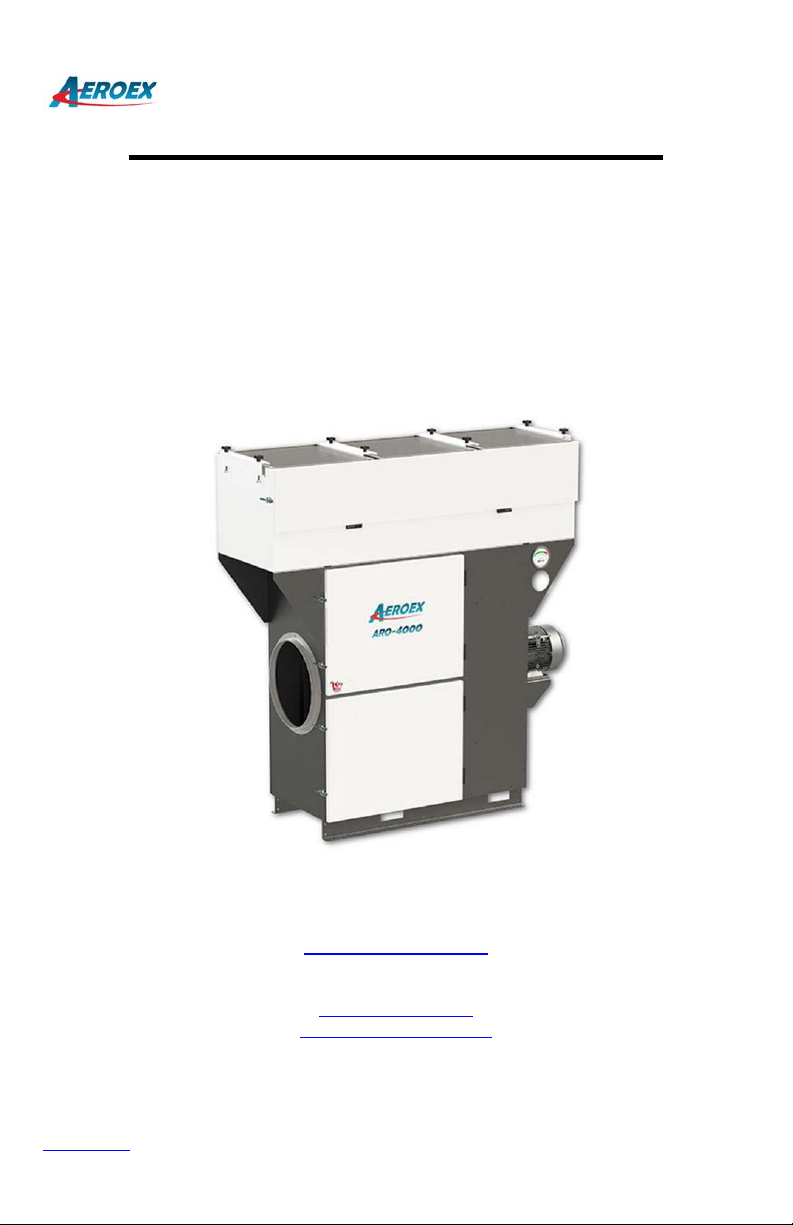
Oil Mist Collector
Model ARO-4000
Multi-Stage
Installation & Service Manual
www.aeroex.com
Sales
905-655-7295
sales@aeroex.com
orderdesk@aeroex.com

2
01/20
www.aeroex.com [email protected]
Table Of Contents
Specifications…………………………………….………….…………3
Installation Instructions……….……….......…………….……………4
Installation Kit.................................................................................5
Oil drain hose Kit............................................................................5
Electrical Connection.....................................................................6
Direction of rotation........................................................................6
Wiring Connection..........................................................................7
Maintenance...................................................................................8
Filter Options Coolant......................................................................9
Filter Options Oil.............................................................................10
Dimensions.....................................................................................11
Warranty.........................................................................................12

3
01/20
www.aeroex.com [email protected]
Model ARO-4000 Specifications
AEROEX – Oil Mist Collector
For highly effective separation of coolant and oil mists including smoke from metalworking
machinery and oil reservoirs.
Consisting of:
Powdered coated mild steel housing.
Motor and fan impeller
Primary separation pack consisting of 1st stage ME pack and 2nd stage AG agglo pack,
3rd and 4th stage FB packs.
Final filtration, 5th stage HEPA filter.
Specifications:
Model
CFM
(m³/hr)
Sound
dB(A)
Machine
Tool
Enclosure
Volume ft³
Motor
hp
Voltage
RPM
Amps
RPM
ARO-
4000
3400 - 4100
(5775 - 6965)
74
4000
7.5
230/3/60
460/3/60
575/3/60
17
8.5
6.8
3450
Model
Dimensions
Weight
Duct Con.
ARO-
2000
74” x 25” x 79”ht (1880 x 635 x 2007 mm)
1200 lb (544 kg)
18” (457 mm)

4
01/20
www.aeroex.com [email protected]
Installation Instructions
•Mount mist collector level.
•Units can be mounted directly on top of machines, on a post or on the wall.
•Ensure that there is free space to change filters.
•Minimize the length of ducting to avoid air flow loses.
•Metal ducting or flexible hose can be used.
•Do not locate suction intake on machining applications in direct line of the cutting spray.
•Install chip strainer. See details next page
•Connect the oil drain line using loop in hose or pee trap.
•Loop in hose must be minimum 8” below mist collector, no max. See instructions page 5.
•Fill loop with water or oil to create air lock.
•Install motor starter and set overloads.
•Connect electrical power.
•Check motor direction as per arrow on motor.
5
01/20
www.aeroex.com [email protected]
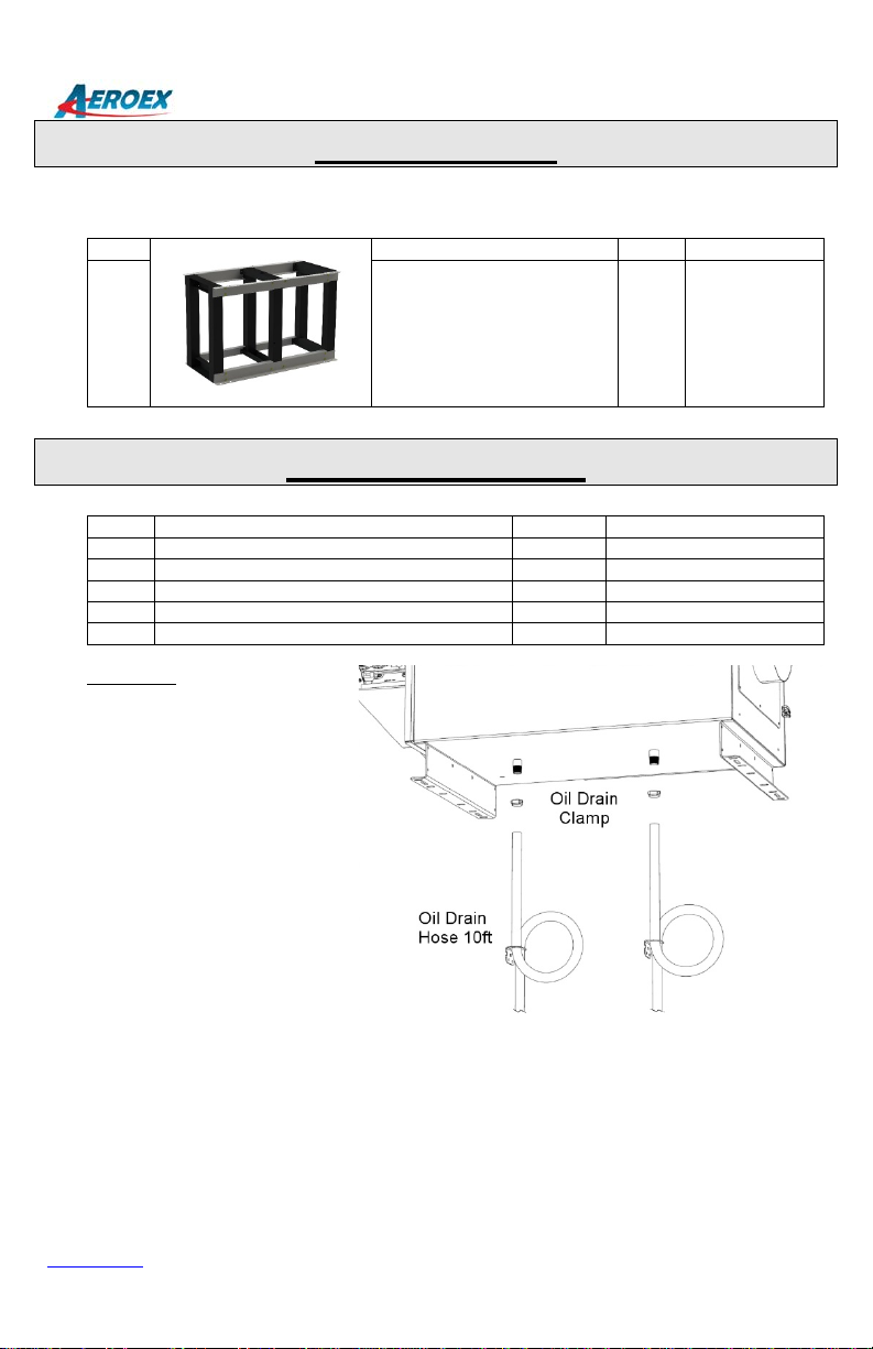
Installation Kit
Three (3) standard installation kits as follows:
Item
Description
Qty
Part #
1
Stand
1
099AMP-0004
Oil Drain Hose Kit
Item
Description
Qty
Part #
1
Drain Hose Kit, c/w
1
099MPH-0013
1(a)
Oil drain hose
10ft
099MPH-0004
1(b)
Oil drain bracket
1
A99SPM-0002
1(c)
Nipple
1
099MPB-0001
1(d)
Hose clamp
1
099MHH-0002
Installation:
Loop in oil drain hose is required
to create air lock.
Fill with water, coolant or oil.
Failure to install correctly will
result in no oil draining

6
01/20
www.aeroex.com [email protected]
Electrical Connection
Electrical installation must be performed by a qualified electrical technician and comply with
applicable local codes. The motor must have overload protection set to the correct motor
amperage.
Most electrical technicians/contractors will be able to supply motor starter panel or install
motor contactor in cnc machine electrical panel.
Aeroex offers a selection of motor starter panels as listed below:
1
Manual Motor
Starter Switch
Start/stop,
overloads, no pilot
light
4
Motor Starter Panel
Remote control with
24 VDC signal
Fused disconnect
switch, overloads,
pilot light.
2
Motor Starter Panel
NEMA 12
Start/stop,
overloads, pilot light
5
VFD Motor Starter
NEMA 4X
enclosure.
3
Motor Starter Panel
Fused disconnect
switch, start/stop,
overloads, pilot light.
6
VFD Motor Starter
Panel
Fused disconnect
switch, start/stop,
overloads, pilot light.
Mount the motor starter control panel in a convenient location.
Machine mounted mist collectors can be wired into the CNC electrical control.
Connect electrical wires on dual voltage motors (230/460/360) according to wire numbers on
table.
Direction of Rotation
Motor: (ARO-4000)
- Motor direction arrow is located on the motor
- Start/Stop motor
- Check rotation direction
- If incorrect, switch 2 electrical connections, i.e. L1 & L2 (3 phase only)
- Recheck

8
01/20
www.aeroex.com [email protected]
Maintenance
The mist collector can operate for long periods without maintenance. The maintenance period will
depend on the type of oil, coolant & debris in air stream. Inspect the unit after 3 months, 6 months
& 1 year to establish the maintenance interval.
Some coolant concentrates will congeal requiring the 1st stage mechanical separator elements and
the 2nd stage agglomerator filter to be manually cleaned/washed. If this is frequent, suggest
installing the optional On-Line Cleaning System.
Debris / swarf can be high on cast iron machining and grinding. If filter cleaning is frequent,
suggest installing the On-Line Cleaning System.
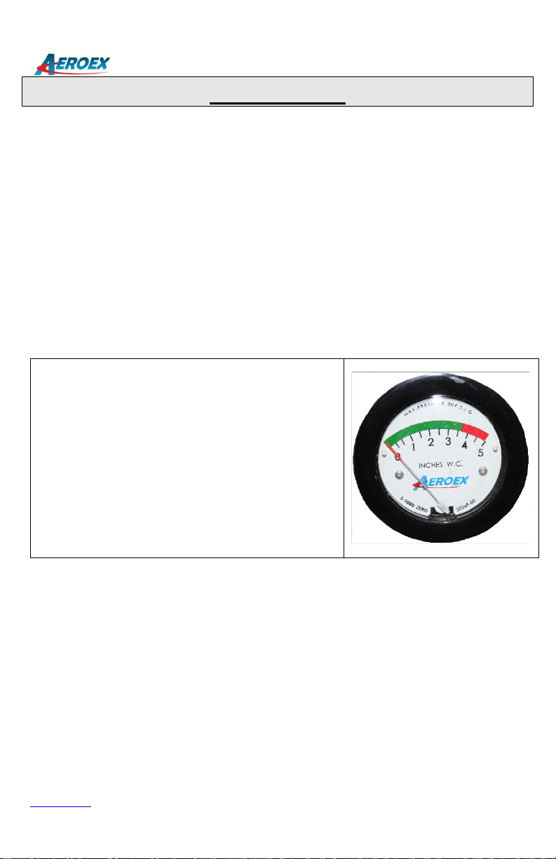
The mist collector has one magnehelic gauge measuring the pressure drop on 4th stage HEPA
filter. Should the gauge reduce to near zero, this indicates no air flow going to HEPA filter, check
filter stages 1 to 4 and chip strainer.
HEPA filter replacement:
Replace when magnehelic pressure gauge
reaches the red zone.
Note:
If filter stages 1 – 3 or chip strainer are plugged, no air flow
will go to 4th stage HEPA filter and pressure reading can
reduce.
9
01/20
www.aeroex.com [email protected]
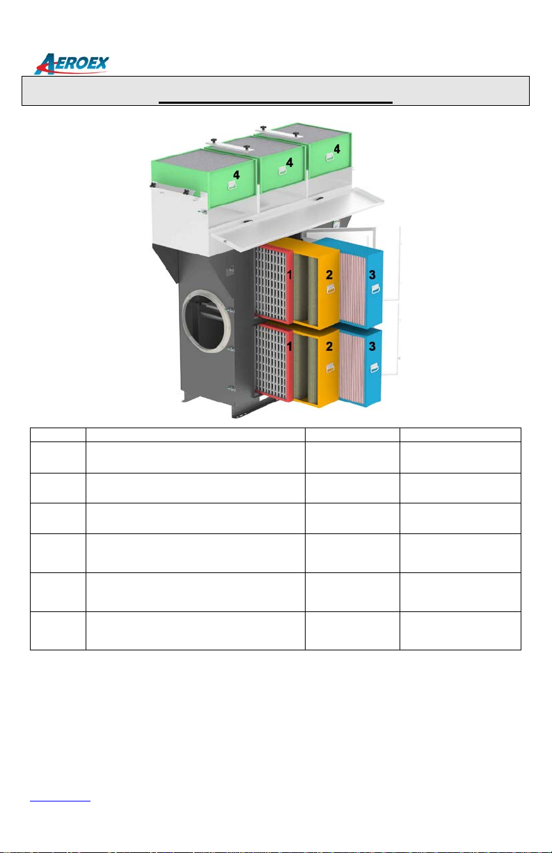
Filter Options Coolant
Note:
Please check filter part # installed in mist collector.
Item #
Description
Quantity
Part Number
1
1st stage “ME” Mechanical Element
2
A20FMS-0001
2
2nd stage “AF” Coolant Filter
2
A20FAF-0001
3
3rd stage “CM” Coolant Mist Filter
2
A20FCM-0004
4
4th stage “HF” HEPA Filter 95% @ 0.3
microns
3
2000HF-2095
4
4th stage “HF” HEPA Filter HEPA 99.97%
@ 0.3 microns
(Optional)
3
2000HF-2099
4
4th stage “HF” Odor-Rid HEPA Filter
(Optional)
3
2000HF-3095

10
01/20
www.aeroex.com [email protected]
Filter Options Oil
Note:
Please check filter part # installed in mist collector.
Item #
Description
Quantity
Part Number
1
1st stage “ME” Mechanical Element
2
A20FMS-0001
2
2nd stage “DE” Demister Element
2
A20FDE-0002
3
3rd Stage “OM#5” Oil Mist Fibre Bed
Filter
2
A20FOM-0005
4
4th Stage “OM#7” Oil Mist Fibre Bed
Filter
2
A20FOM-0007
5
5th stage “HF” HEPA Filter 95% @ 0.3
microns
3
2000HF-2095
5
5th stage “HF” HEPA Filter HEPA 99.97%
@ 0.3 microns
(Optional)
3
2000HF-2099
5
5th stage “HF” Odor-Rid HEPA Filter
(Optional)
3
2000HF-3095


12
01/20
www.aeroex.com [email protected]
Warranty
Limited Warranty
Aeroex warrants the original purchaser against defects in material and workmanship for five (5)
years from date of shipment.
Filters are consumable items and are only warranted to be free of manufacturing defects at time of
delivery.
Equipment, parts, or accessories manufactured by others including electric motor, fans and control
components carry the guaranty of the manufacturer only.
Any part which is determined to be defective in material or workmanship and returned to an
authorized service location, as Aeroex Technologies designates, shipping costs prepaid, will be
repaired or replaced at Aeroex Technologies option.
Excluded from the foregoing guarantee are damages caused by ordinary wear and tear, erosion or
corrosion, misuse, abuse, or improper handling by the purchaser or any third party.
Aeroex Technologies makes no additional warranties, expressed or implied, whether of
merchantability, or otherwise, other than stated above. AEROEX shall not be responsible for any
indirect, special or consequential damages, nor for any other claim arising out of the sale, rental, or
use of its equipment. AEROEX shall not be liable for special or consequent damages in case of any
failure, claims for labour, loss of profits, repairs, alterations, or other expenses incidental to
replacement of defective parts or return of the equipment. The Purchaser's sole remedy shall be as
stated above.
Aeroex Technologies will make good faith effort for prompt correction or adjustment with respect to
any product that proves to be defective within warranty.
Aeroex Technologies Inc.
17 Hamilton Road
Barrie ON, L4N 8Y6
705-734-0199
Sales 905-655-7295
orderdesk@aeroex.com
www.aeroex.com
This manual suits for next models
1
Table of contents
Popular Dust Collector manuals by other brands


djm direct
djm direct DJM01980-1 Original operating manual

Quatro
Quatro Premium SPH Series Instruction & maintenance manual

HOLZMANN MASCHINEN
HOLZMANN MASCHINEN ABS 2200FLEX user manual

PuriSystems
PuriSystems PuriCare 500 user manual

Bartell
Bartell CONTEC KAESER R2D2 Owner's manual and parts book

Oneida Air Systems
Oneida Air Systems Mini GORILLA XXP010101 owner's manual

Oneida Air Systems
Oneida Air Systems 2 HP Commercial Cyclonic Dust Collector owner's manual

WAM
WAM SILOTOP R03 Installation operation & maintenance

Grizzly
Grizzly G0443 owner's manual

Jet
Jet DC-1200C owner's manual

NuTone
NuTone VAC PAN CI-365 installation instructions

OHM ELECTRIC
OHM ELECTRIC MIST CATCH OMC-F105A instruction manual