Aeroflex GPSG-1000 User manual

Maintenance Manual
Positional Simulator
GPS/Galileo
GPSG-1000
EXPORT CONTROL WARNING: This document contains controlled
technology or technical data under the jurisdiction of the Export
Administration Regulations (EAR), 15 CFR 730-774. It cannot be
transferred to any foreign third party without the specific prior
approval of the U.S. Department of Commerce Bureau of Industry
and Security BIS). Violations of these regulations are punishable by
fine, imprisonment, or both.
PRELIMINARY

Subject to Export Control, see Cover Page for details.
GPSG-1000
GPS/Galileo Positional Simulator
PRELIMINARY
Maintenance Manual
PUBLISHED BY
Aeroflex
COPYRIGHT ©Aeroflex 2012
All rights reserved. No part of this publication may be reproduced, stored in a retrieval system, or
transmitted in any form or by any means, electronic, mechanical, photocopying, recording or otherwise
without the prior permission of the publisher.
Original Release Nov 2012
10200 West York / Wichita, Kansas 67215 U.S.A. / (316) 522-4981 / FAX (316) 524-2623

Subject to Export Control, see Cover Page for details.

Table of Contents
Subject to Export Control, see Cover Page for details.
iii
Table of Contents
Chapter 1 - Introduction . . . . . . . . . . . . . . . . . . . . . . . . 1 - 1
Principles of Operation . . . . . . . . . . . . . . . . . . . . . . . . . . . . . . . . . . . . . . . . . . . . . . 1 - 1
GPSG-1000 . . . . . . . . . . . . . . . . . . . . . . . . . . . . . . . . . . . . . . . . . . . . . . . . . . . 1 - 1
Interconnect Block Diagrams . . . . . . . . . . . . . . . . . . . . . . . . . . . . . . . . . . . . . . . 1 - 3
GPS System . . . . . . . . . . . . . . . . . . . . . . . . . . . . . . . . . . . . . . . . . . . . . . . . . . . 1 - 4
SPS Standard Positioning Service . . . . . . . . . . . . . . . . . . . . . . . . . . . . . . . . . . . 1 - 7
Position Calculation . . . . . . . . . . . . . . . . . . . . . . . . . . . . . . . . . . . . . . . . . . . . . 1 - 8
GPS Timekeeping . . . . . . . . . . . . . . . . . . . . . . . . . . . . . . . . . . . . . . . . . . . . . . 1 - 20
GNSS Accuracy . . . . . . . . . . . . . . . . . . . . . . . . . . . . . . . . . . . . . . . . . . . . . . . 1 - 21
GNSS Augmentation . . . . . . . . . . . . . . . . . . . . . . . . . . . . . . . . . . . . . . . . . . . . 1 - 22
GPS Modernization Signals . . . . . . . . . . . . . . . . . . . . . . . . . . . . . . . . . . . . . . . 1 - 25
The Galileo System . . . . . . . . . . . . . . . . . . . . . . . . . . . . . . . . . . . . . . . . . . . . 1 - 29
Chapter 2 - Troubleshooting . . . . . . . . . . . . . . . . . . . . . 2 - 1
General Information . . . . . . . . . . . . . . . . . . . . . . . . . . . . . . . . . . . . . . . . . . . . . . . . 2 - 1
Preventive Maintenance Procedures . . . . . . . . . . . . . . . . . . . . . . . . . . . . . . . . . . 2 - 1
Troubleshooting Guidelines . . . . . . . . . . . . . . . . . . . . . . . . . . . . . . . . . . . . . . . . 2 - 2
Tool Requirements . . . . . . . . . . . . . . . . . . . . . . . . . . . . . . . . . . . . . . . . . . . . . . 2 - 3
TBD . . . . . . . . . . . . . . . . . . . . . . . . . . . . . . . . . . . . . . . . . . . . . . . . . . . . . . . . 2 - 3
Safety Precautions . . . . . . . . . . . . . . . . . . . . . . . . . . . . . . . . . . . . . . . . . . . . . . 2 - 4
EMC/Safety Compliance . . . . . . . . . . . . . . . . . . . . . . . . . . . . . . . . . . . . . . . . . . 2 - 4
Chapter 3 - Calibration/Verification . . . . . . . . . . . . . . . . 3 - 1
General Information . . . . . . . . . . . . . . . . . . . . . . . . . . . . . . . . . . . . . . . . . . . . . . . . 3 - 1
Testing Conditions . . . . . . . . . . . . . . . . . . . . . . . . . . . . . . . . . . . . . . . . . . . . . . 3 - 1
Required Equipment . . . . . . . . . . . . . . . . . . . . . . . . . . . . . . . . . . . . . . . . . . . . . 3 - 1
Safety Precautions . . . . . . . . . . . . . . . . . . . . . . . . . . . . . . . . . . . . . . . . . . . . . . 3 - 1
Test Set Calibration . . . . . . . . . . . . . . . . . . . . . . . . . . . . . . . . . . . . . . . . . . . . . . . . 3 - 2
Calibration Schedule . . . . . . . . . . . . . . . . . . . . . . . . . . . . . . . . . . . . . . . . . . . . . 3 - 2
Preliminary Procedures . . . . . . . . . . . . . . . . . . . . . . . . . . . . . . . . . . . . . . . . . . . 3 - 2
Test Setup . . . . . . . . . . . . . . . . . . . . . . . . . . . . . . . . . . . . . . . . . . . . . . . . . . . . 3 - 3
Test Equipment . . . . . . . . . . . . . . . . . . . . . . . . . . . . . . . . . . . . . . . . . . . . . . . . 3 - 3
Test Set Calibration Procedure . . . . . . . . . . . . . . . . . . . . . . . . . . . . . . . . . . . . . 3 - 3
Calibration Menu . . . . . . . . . . . . . . . . . . . . . . . . . . . . . . . . . . . . . . . . . . . . . . . 3 - 4
Reference Frequency Calibration . . . . . . . . . . . . . . . . . . . . . . . . . . . . . . . . . . . . 3 - 5
Output Level Calibration . . . . . . . . . . . . . . . . . . . . . . . . . . . . . . . . . . . . . . . . . . 3 - 5
Test Set Verification . . . . . . . . . . . . . . . . . . . . . . . . . . . . . . . . . . . . . . . . . . . . . . . 3 - 6

Table of Contents
Subject to Export Control, see Cover Page for details.
iv
Verification Schedule . . . . . . . . . . . . . . . . . . . . . . . . . . . . . . . . . . . . . . . . . . . . 3 - 6
Precautions . . . . . . . . . . . . . . . . . . . . . . . . . . . . . . . . . . . . . . . . . . . . . . . . . . . 3 - 6
Test Equipment . . . . . . . . . . . . . . . . . . . . . . . . . . . . . . . . . . . . . . . . . . . . . . . . 3 - 6
Test Setup . . . . . . . . . . . . . . . . . . . . . . . . . . . . . . . . . . . . . . . . . . . . . . . . . . . . 3 - 7
Preset Conditions . . . . . . . . . . . . . . . . . . . . . . . . . . . . . . . . . . . . . . . . . . . . . . . 3 - 8
Remote Communication . . . . . . . . . . . . . . . . . . . . . . . . . . . . . . . . . . . . . . . . . . . 3 - 9
Static Simulation . . . . . . . . . . . . . . . . . . . . . . . . . . . . . . . . . . . . . . . . . . . . . . 3 - 11
GPS Receiver Test and Loopback Operation . . . . . . . . . . . . . . . . . . . . . . . . . . . 3 - 13
External Trigger Input . . . . . . . . . . . . . . . . . . . . . . . . . . . . . . . . . . . . . . . . . . . 3 - 16
Internal 10 MHz Reference . . . . . . . . . . . . . . . . . . . . . . . . . . . . . . . . . . . . . . . 3 - 20
External 10 MHz Reference . . . . . . . . . . . . . . . . . . . . . . . . . . . . . . . . . . . . . . . 3 - 21
VSWR at Antenna Port . . . . . . . . . . . . . . . . . . . . . . . . . . . . . . . . . . . . . . . . . . 3 - 23
VSWR at Direct Port . . . . . . . . . . . . . . . . . . . . . . . . . . . . . . . . . . . . . . . . . . . . 3 - 24
RF Output Frequency . . . . . . . . . . . . . . . . . . . . . . . . . . . . . . . . . . . . . . . . . . . 3 - 25
RF Output Harmonics . . . . . . . . . . . . . . . . . . . . . . . . . . . . . . . . . . . . . . . . . . . 3 - 26
RF Output Spurious Levels . . . . . . . . . . . . . . . . . . . . . . . . . . . . . . . . . . . . . . . 3 - 28
RF Output Level at Antenna Port . . . . . . . . . . . . . . . . . . . . . . . . . . . . . . . . . . . 3 - 30
RF Output Level at Direct Port . . . . . . . . . . . . . . . . . . . . . . . . . . . . . . . . . . . . . 3 - 32
1 PPS Output Signal . . . . . . . . . . . . . . . . . . . . . . . . . . . . . . . . . . . . . . . . . . . . 3 - 34
Chapter 4 - Remove/Install Procedures . . . . . . . . . . . . . 4 - 1
General Information . . . . . . . . . . . . . . . . . . . . . . . . . . . . . . . . . . . . . . . . . . . . . . . . 4 - 1
Preliminary Considerations . . . . . . . . . . . . . . . . . . . . . . . . . . . . . . . . . . . . . . . . . . . 4 - 1
Tools Requirements . . . . . . . . . . . . . . . . . . . . . . . . . . . . . . . . . . . . . . . . . . . . . 4 - 1
ESD and Safety Precautions . . . . . . . . . . . . . . . . . . . . . . . . . . . . . . . . . . . . . . . 4 - 1
Specified Replacement Screws . . . . . . . . . . . . . . . . . . . . . . . . . . . . . . . . . . . . . 4 - 1
Inverting Test Set . . . . . . . . . . . . . . . . . . . . . . . . . . . . . . . . . . . . . . . . . . . . . . . 4 - 2
Connectors and Cables . . . . . . . . . . . . . . . . . . . . . . . . . . . . . . . . . . . . . . . . . . . 4 - 2
Preliminary Procedures . . . . . . . . . . . . . . . . . . . . . . . . . . . . . . . . . . . . . . . . . . . 4 - 2
Chapter 5 - Parts List . . . . . . . . . . . . . . . . . . . . . . . . . . 5 - 1
Parts List . . . . . . . . . . . . . . . . . . . . . . . . . . . . . . . . . . . . . . . . . . . . . . . . . . . . . . . 5 - 2
Ship Unit, GPSG1000 (A1) . . . . . . . . . . . . . . . . . . . . . . . . . . . . . . . . . . . . . . . . . 5 - 2
Mechanical Assembly (A1A1) . . . . . . . . . . . . . . . . . . . . . . . . . . . . . . . . . . . . . . . 5 - 3
Base Mechnical Assembly (A1A2) . . . . . . . . . . . . . . . . . . . . . . . . . . . . . . . . . . . . 5 - 4
Chapter 6 - Assembly and Interconnect Drawings . . . . . 6 - 1
Drawings List . . . . . . . . . . . . . . . . . . . . . . . . . . . . . . . . . . . . . . . . . . . . . . . . . . . . 6 - 1
GPSG-1000 Ship Unit . . . . . . . . . . . . . . . . . . . . . . . . . . . . . . . . . . . . . . . . . . . . . . . 6 - 3
GPSG-1000 Interconnect Diagram . . . . . . . . . . . . . . . . . . . . . . . . . . . . . . . . . . . . . . 6 - 5
GPSG-1000 MECHANICAL Assembly . . . . . . . . . . . . . . . . . . . . . . . . . . . . . . . . . . . . 6 - 6
GPSG-1000 driver board Assembly . . . . . . . . . . . . . . . . . . . . . . . . . . . . . . . . . . . . . 6 - 7
GPSG-1000 panel Control Assembly . . . . . . . . . . . . . . . . . . . . . . . . . . . . . . . . . . . . 6 - 8
GPSG-1000 168 Color, 12.1” SVGA TFT, 1000 NITS Assembly . . . . . . . . . . . . . . . . . . 6 - 9

Table of Contents
Subject to Export Control, see Cover Page for details.
v
GPSG-1000 panel touchscreen Assembly . . . . . . . . . . . . . . . . . . . . . . . . . . . . . . . . 6 - 10
GPSG-1000 touchscreen Control Assembly . . . . . . . . . . . . . . . . . . . . . . . . . . . . . . . 6 - 11
GPSG-1000 base mech assembly . . . . . . . . . . . . . . . . . . . . . . . . . . . . . . . . . . . . . 6 - 12
GPSG-1000 GPS chasis mech Assembly . . . . . . . . . . . . . . . . . . . . . . . . . . . . . . . . 6 - 14
GPSG-1000 base card cage mech assembly . . . . . . . . . . . . . . . . . . . . . . . . . . . . . . 6 - 15
GPSG-1000 torpedo Assembly . . . . . . . . . . . . . . . . . . . . . . . . . . . . . . . . . . . . . . . . 6 - 17
gpsg-1000 Digital PCB Assembly . . . . . . . . . . . . . . . . . . . . . . . . . . . . . . . . . . . . . . 6 - 18
gpsg-1000 rf upconverter PCB Assembly . . . . . . . . . . . . . . . . . . . . . . . . . . . . . . . . 6 - 19
gpsg-1000 rf combiner pcb Assembly . . . . . . . . . . . . . . . . . . . . . . . . . . . . . . . . . . . 6 - 20
GPSG-1000 GPS RX pcb Assembly . . . . . . . . . . . . . . . . . . . . . . . . . . . . . . . . . . . . 6 - 21
gpsg-1000 auxiliary interface gps pcb Assembly . . . . . . . . . . . . . . . . . . . . . . . . . . . 6 - 22
Appendix A - Pin-Out Tables . . . . . . . . . . . . . . . . . . . . .A - 1
Appendix B - Abbreviations . . . . . . . . . . . . . . . . . . . . .B - 1
Abbreviations . . . . . . . . . . . . . . . . . . . . . . . . . . . . . . . . . . . . . . . . . . . . . . . . . . . . B - 1
Appendix C - Test Equipment . . . . . . . . . . . . . . . . . . . .C - 1
Test Equipment . . . . . . . . . . . . . . . . . . . . . . . . . . . . . . . . . . . . . . . . . . . . . . . . . . . C - 1
Appendix D - Controls and Connectors . . . . . . . . . . . . .D - 1
Front Panel Controls and Connectors . . . . . . . . . . . . . . . . . . . . . . . . . . . . . . . . . . . . D - 1
Rear Panel Controls and Connectors . . . . . . . . . . . . . . . . . . . . . . . . . . . . . . . . . . . . D - 3

List of Figures
Subject to Export Control, see Cover Page for details.
1
List of Figures
TITLE PAGE
Assembly Interconnect Block Diagram) . . . . . . . . . . . . . . . . . . . . . . . . . . . . . . . . . . 1 - 3
GPS System Segments . . . . . . . . . . . . . . . . . . . . . . . . . . . . . . . . . . . . . . . . . . . . . . 1 - 4
GPS Satellite . . . . . . . . . . . . . . . . . . . . . . . . . . . . . . . . . . . . . . . . . . . . . . . . . . . . . 1 - 5
GPS Satellite Orbital Planes . . . . . . . . . . . . . . . . . . . . . . . . . . . . . . . . . . . . . . . . . . 1 - 5
GPS SV Block Schematic . . . . . . . . . . . . . . . . . . . . . . . . . . . . . . . . . . . . . . . . . . . . 1 - 6
GPS SV Signal Data Structure . . . . . . . . . . . . . . . . . . . . . . . . . . . . . . . . . . . . . . . . . 1 - 6
GPS Monitor Stations . . . . . . . . . . . . . . . . . . . . . . . . . . . . . . . . . . . . . . . . . . . . . . . 1 - 7
GPS Navigation Data . . . . . . . . . . . . . . . . . . . . . . . . . . . . . . . . . . . . . . . . . . . . . . . 1 - 8
GPS Almanac . . . . . . . . . . . . . . . . . . . . . . . . . . . . . . . . . . . . . . . . . . . . . . . . . . . . 1 - 9
Satellite Relative Position . . . . . . . . . . . . . . . . . . . . . . . . . . . . . . . . . . . . . . . . . . . 1 - 10
GPS Received Signal . . . . . . . . . . . . . . . . . . . . . . . . . . . . . . . . . . . . . . . . . . . . . . 1 - 11
GPS Received Signal . . . . . . . . . . . . . . . . . . . . . . . . . . . . . . . . . . . . . . . . . . . . . . 1 - 11
GPS Code Correlation Process . . . . . . . . . . . . . . . . . . . . . . . . . . . . . . . . . . . . . . . 1 - 12
GPS Nav Data Recover by Moduo 2 Addition . . . . . . . . . . . . . . . . . . . . . . . . . . . . . 1 - 12
GPS Signal After De-spreading . . . . . . . . . . . . . . . . . . . . . . . . . . . . . . . . . . . . . . . 1 - 13
GPS Subframe Hand-Over Word . . . . . . . . . . . . . . . . . . . . . . . . . . . . . . . . . . . . . . 1 - 14
GPS Pseudo Range . . . . . . . . . . . . . . . . . . . . . . . . . . . . . . . . . . . . . . . . . . . . . . . 1 - 15
GPS Pseudo Range . . . . . . . . . . . . . . . . . . . . . . . . . . . . . . . . . . . . . . . . . . . . . . . 1 - 16
Triangulation using one known point . . . . . . . . . . . . . . . . . . . . . . . . . . . . . . . . . . . 1 - 16
Triangulation using two known point . . . . . . . . . . . . . . . . . . . . . . . . . . . . . . . . . . . 1 - 17
Triangulation using three known point . . . . . . . . . . . . . . . . . . . . . . . . . . . . . . . . . . 1 - 17
Triangulation using two known points in 3D space . . . . . . . . . . . . . . . . . . . . . . . . . . 1 - 17
Triangulation using three known points in 3D space . . . . . . . . . . . . . . . . . . . . . . . . . 1 - 18
Multipath Delays . . . . . . . . . . . . . . . . . . . . . . . . . . . . . . . . . . . . . . . . . . . . . . . . . 1 - 18
Atmospheric Delays . . . . . . . . . . . . . . . . . . . . . . . . . . . . . . . . . . . . . . . . . . . . . . . 1 - 19
GPS v. UTC Time Format . . . . . . . . . . . . . . . . . . . . . . . . . . . . . . . . . . . . . . . . . . . 1 - 20
SBAS Coverage . . . . . . . . . . . . . . . . . . . . . . . . . . . . . . . . . . . . . . . . . . . . . . . . . . 1 - 22
GPS Modernization Signals . . . . . . . . . . . . . . . . . . . . . . . . . . . . . . . . . . . . . . . . . . 1 - 25
Galileo Satellite (GIOVE Test SV) . . . . . . . . . . . . . . . . . . . . . . . . . . . . . . . . . . . . . 1 - 29
GPSG-1000 Radio Altimeter Test Set . . . . . . . . . . . . . . . . . . . . . . . . . . . . . . . . . . . . 5 - 1
GPSG-1000 Ship Unit (A1) . . . . . . . . . . . . . . . . . . . . . . . . . . . . . . . . . . . . . . . . . . 6 - 3
GPSG-1000 Ship Unit (A1) . . . . . . . . . . . . . . . . . . . . . . . . . . . . . . . . . . . . . . . . . . . 6 - 4
GPSG-1000 Interconnect and Block Diagram . . . . . . . . . . . . . . . . . . . . . . . . . . . . . . 6 - 5
GPSG-1000 Mechanical Assembly (A1A1) . . . . . . . . . . . . . . . . . . . . . . . . . . . . . . . . . 6 - 6
GPSG-1000 Driver Board Assembly (A1A1A1) . . . . . . . . . . . . . . . . . . . . . . . . . . . . . . 6 - 7

List of Figures
Subject to Export Control, see Cover Page for details.
2
GPSG-1000 Panel Control Assembly (A1A1A2) . . . . . . . . . . . . . . . . . . . . . . . . . . . . . 6 - 8
GPSG-1000 168 Color, 12.1” SVGA TFT, 1000 NITS Assembly (A1A1A3) . . . . . . . . . . . 6 - 9
GPSG-1000 Touchscreen Assembly (A1A1A4) . . . . . . . . . . . . . . . . . . . . . . . . . . . . . 6 - 10
GPSG-1000 Touchscreen Control Assembly (A1A1A5) . . . . . . . . . . . . . . . . . . . . . . . 6 - 11
GPSG-1000 Base Mech Assembly (A1A2) . . . . . . . . . . . . . . . . . . . . . . . . . . . . . . . . 6 - 12
GPSG-1000 Base Mech Assembly (A1A2) . . . . . . . . . . . . . . . . . . . . . . . . . . . . . . . . 6 - 13
GPSG-100 GPS Chasis Mech Assembly (A1A2A2) . . . . . . . . . . . . . . . . . . . . . . . . . . 6 - 14
GPSG-1000 RAD/ALT Base Card Cage Mech Assembly (A1A2A2A1) . . . . . . . . . . . . . 6 - 15
GPSG-1000 RAD/ALT Base Card Cage Mech Assembly (A1A2A2A1) . . . . . . . . . . . . . 6 - 16
GPSG-1000 Torpedo Assembly (A1A2A2A1A1A1) . . . . . . . . . . . . . . . . . . . . . . . . . . 6 - 17
GPSG-1000 Digital PCB Assembly (A1A2A2A2A1) . . . . . . . . . . . . . . . . . . . . . . . . . . 6 - 18
GPSG-1000 RF Upconverter PCB Assembly (A1A2A2A2A2A1) . . . . . . . . . . . . . . . . . 6 - 19
GPSG-1000 RF Combiner PCB Assembly (A1A2A2A3A1) . . . . . . . . . . . . . . . . . . . . . 6 - 20
GPSG-1000 GPS RX PCB Assembly (A1A2A4) . . . . . . . . . . . . . . . . . . . . . . . . . . . . 6 - 21
GPSG-1000 Auxiliary Interface GPS PCB Assembly (A1A2A5) . . . . . . . . . . . . . . . . . 6 - 22
Ethernet Pin-Out Diagram . . . . . . . . . . . . . . . . . . . . . . . . . . . . . . . . . . . . . . . . . . . . A - 1
USB Host 1 Pin-Out Diagram . . . . . . . . . . . . . . . . . . . . . . . . . . . . . . . . . . . . . . . . . A - 1
USB Host 2 Pin-Out Diagram . . . . . . . . . . . . . . . . . . . . . . . . . . . . . . . . . . . . . . . . . A - 2
USB OTG Pin-Out Diagram . . . . . . . . . . . . . . . . . . . . . . . . . . . . . . . . . . . . . . . . . . . A - 2
DC Power Connector Pin-Out Diagram . . . . . . . . . . . . . . . . . . . . . . . . . . . . . . . . . . . A - 2
AUX Connector Pin-Out Diagram . . . . . . . . . . . . . . . . . . . . . . . . . . . . . . . . . . . . . . . A - 3
Front Panel Controls . . . . . . . . . . . . . . . . . . . . . . . . . . . . . . . . . . . . . . . . . . . . . . . D - 1
Test Set Rear Panel Controls and Connectors . . . . . . . . . . . . . . . . . . . . . . . . . . . . . . D - 3

PRELIMINARY
Subject to Export Control, see Cover Page for details.
i
ELECTROMAGNETIC COMPATIBILITY
Double shielded and properly terminated external interface cables must be used with this equipment
when interfacing with the RS-232 and Ethernet.
For continued EMC compliance, all external cables must be shielded and 3 meters or less in length.
NOMENCLATURE STATEMENT
In this manual, GPSG-1000, Test Set or Unit refers to the GPSG-1000 GPS/Galileo Positional Simulator.

PRELIMINARY
Subject to Export Control, see Cover Page for details.
ii
THIS PAGE INTENTIONALLY LEFT BLANK.

PRELIMINARY
Subject to Export Control, see Cover Page for details.
iii
Declaration of Conformity
The Declaration of Conformity Certificate included with the Unit should remain with the
Unit.
Aeroflex recommends the operator reproduce a copy of the Declaration of Conformity
Certificate to be stored with the Operation Manual for future reference.

PRELIMINARY
Declaration of Conformity
Subject to Export Control, see Cover Page for details.
iv
THIS PAGE INTENTIONALLY LEFT BLANK.
PRELIMINARY
Subject to Export Control, see Cover Page for details.
v
Precautions
SAFETY FIRST - TO ALL OPERATIONS PERSONNEL
GENERAL CONDITIONS OF USE
This product is designed and tested to comply with the requirements of IEC/EN61010-1 ‘Safety
requirements for electrical equipment for measurement, control and laboratory use’ for Class I portable
equipment and is for use in a pollution degree 2 environment. The equipment is designed to operate
from installation supply Category II.
Equipment should be protected from liquids such as spills, leaks, etc. and precipitation such as rain,
snow, etc. When moving the equipment from a cold to hot environment, allow the temperature of the
equipment to stabilize before it is connected to the supply to avoid condensation forming. The
equipment must only be operated within the environmental conditions specified in the performance data.
This product is not approved for use in hazardous atmospheres or medical applications. If the
equipment is to be used in a safety-related application, such as avionics or military applications, the
suitability of the product must be assessed and approved for use by a competent person.
CASE, COVER OR PANEL REMOVAL
Opening the Case Assembly exposes the operator to electrical hazards that may result in electrical
shock or equipment damage. Do not operate this Test Set with the Case Assembly open.
SAFETY IDENTIFICATION IN TECHNICAL MANUAL
This manual uses the following terms to draw attention to possible safety hazards that may exist when
operating or servicing this equipment:
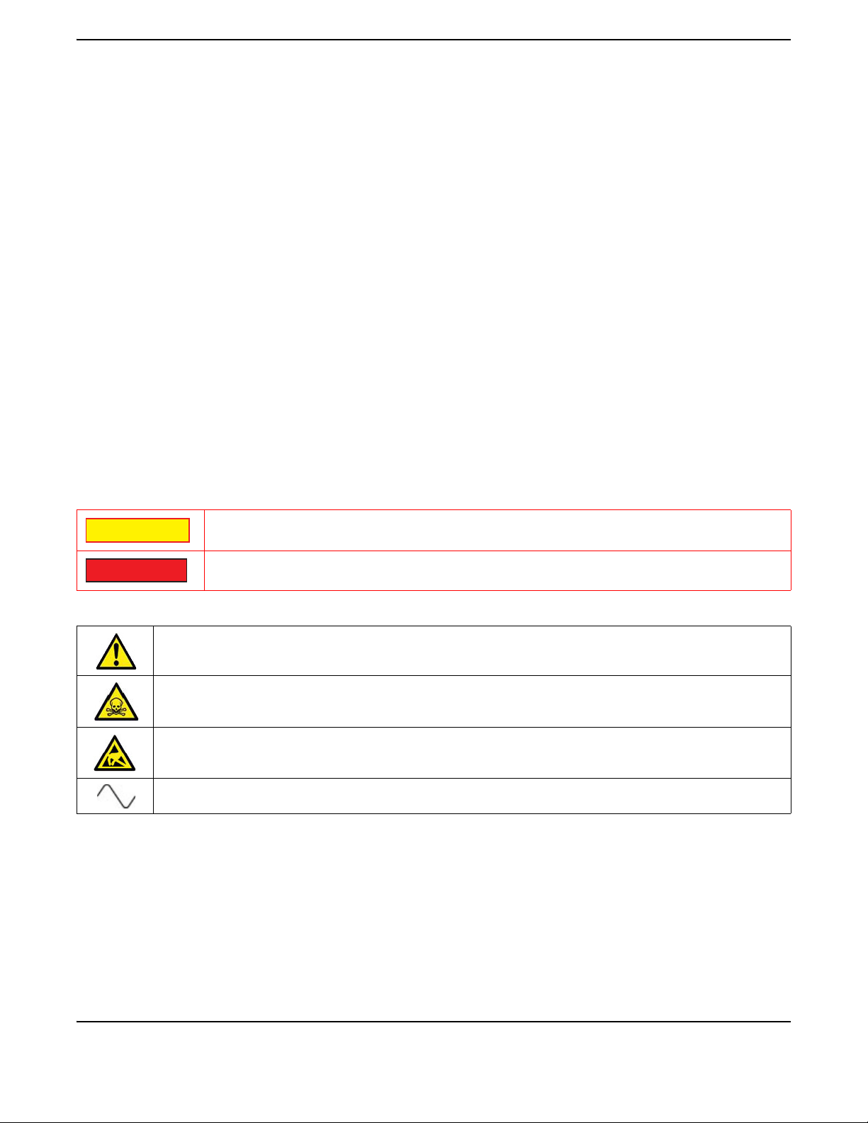
SAFETY SYMBOLS IN MANUALS AND ON UNITS
IDENTIFIES CONDITIONS OR ACTIVITIES THAT, IF IGNORED, CAN RESULT IN
EQUIPMENT OR PROPERTY DAMAGE, E.G., FIRE.
IDENTIFIES CONDITIONS OR ACTIVITIES THAT, IF IGNORED, CAN RESULT IN
PERSONAL INJURY OR DEATH.
CAUTION: Refer to accompanying documents. (This symbol refers to specific CAUTIONS
represented on the unit and clarified in the text.)
Indicates a Toxic hazard.
Indicates item is static sensitive.
AC TERMINAL: Terminal that may supply or be supplied with AC or alternating voltage.
CAUTION
WARNING
PRELIMINARY
Precautions
Subject to Export Control, see Cover Page for details.
vi
SAFETY FIRST - TO ALL OPERATIONS PERSONNEL (cont)
EQUIPMENT GROUNDING PROTECTION
Improper grounding of equipment can result in electrical shock.
USE OF PROBES
Refer to Performance Specifications for the maximum voltage, current and power ratings of any
connector on the Test Set before connecting it with a probe from a terminal device. Be sure the terminal
device performs within these specifications before using it for measurement, to prevent electrical shock
or damage to the equipment.
POWER CORDS
Power cords must not be frayed or broken, nor expose bare wiring when operating this equipment.
USE RECOMMENDED FUSES ONLY
Use only fuses specifically recommended for the equipment at the specified current and voltage ratings.
Refer to Performance Specifications for fuse requirements and specifications.
INTERNAL BATTERY
This unit contains a Lithium Ion Battery, serviceable only by a qualified technician.
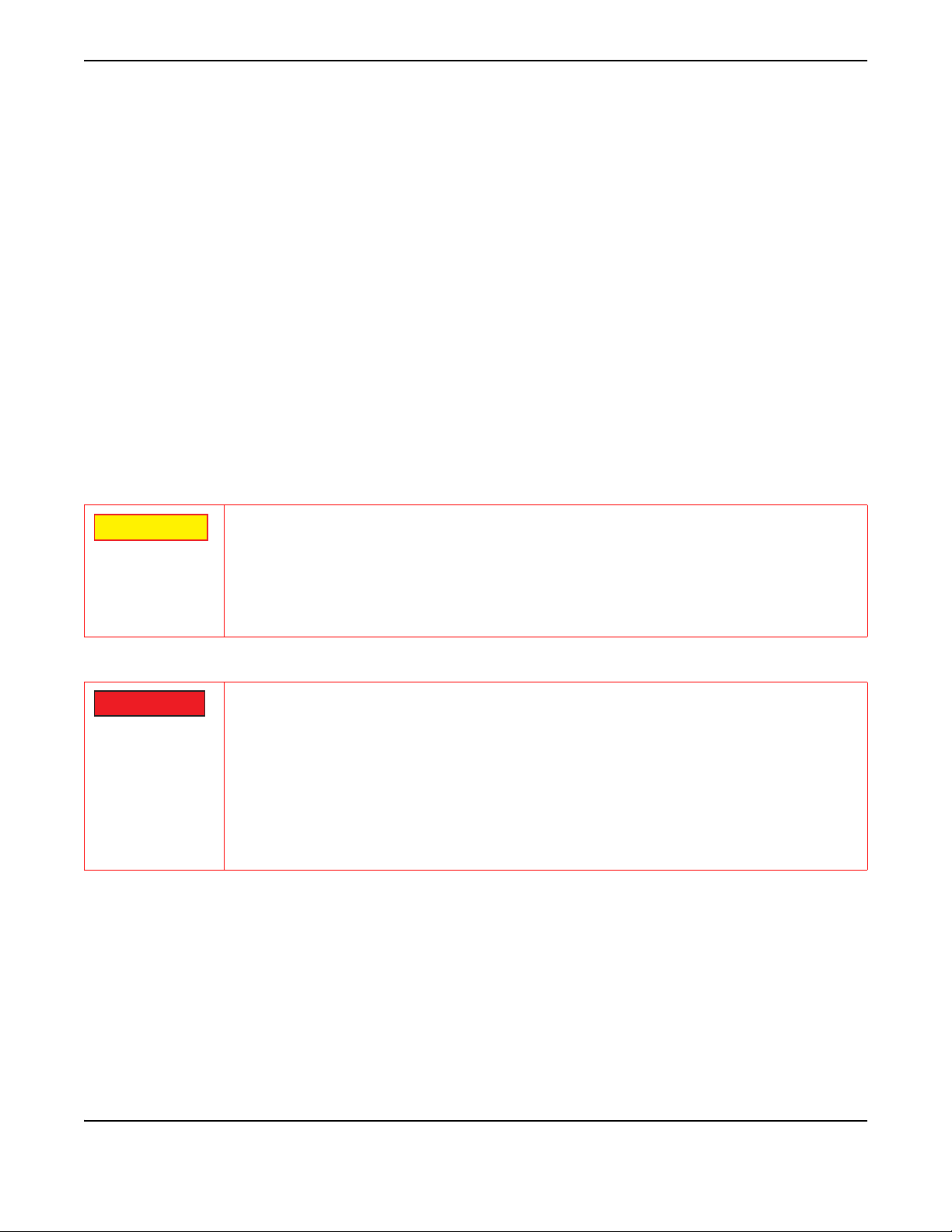
EMI (ELECTROMAGNETIC INTERFERENCE
ELECTRICAL HAZARDS (AC SUPPLY VOLTAGE)
SIGNAL GENERATORS CAN BE A SOURCE OF ELECTROMAGNETIC
INTERFERENCE (EMI) TO COMMUNICATION RECEIVERS. SOME TRANSMITTED
SIGNALS CAN CAUSE DISRUPTION AND INTERFERENCE TO COMMUNICATION
SERVICE OUT TO A DISTANCE OF SEVERAL MILES. USER OF THIS EQUIPMENT
SHOULD SCRUTINIZE ANY OPERATION THAT RESULTS IN RADIATION OF A
SIGNAL (DIRECTLY OR INDIRECTLY) AND SHOULD TAKE NECESSARY
PRECAUTIONS TO AVOID POTENTIAL COMMUNICATION INTERFERENCE
PROBLEMS.
THIS EQUIPMENT IS PROVIDED WITH A PROTECTIVE GROUNDING LEAD THAT
CONFORMS WITH IEC SAFETY CLASS I. TO MAINTAIN THIS PROTECTION THE
SUPPLY LEAD MUST ALWAYS BE CONNECTED TO THE SOURCE OF SUPPLY
VIA A SOCKET WITH A GROUNDED CONTACT.
BE AWARE THAT THE SUPPLY FILTER CONTAINS CAPACITORS THAT MAY
REMAIN CHARGED AFTER THE EQUIPMENT IS DISCONNECTED FROM THE
SUPPLY. ALTHOUGH THE STORED ENERGY IS WITHIN THE APPROVED
SAFETY REQUIREMENTS, A SLIGHT SHOCK MAY BE FELT IF THE PLUG PINS
ARE TOUCHED IMMEDIATELY AFTER REMOVAL.
DO NOT REMOVE INSTRUMENT COVERS AS THIS MAY RESULT IN PERSONAL
INJURY. THERE ARE NO USER-SERVICEABLE PARTS INSIDE.
CAUTION
WARNING

PRELIMINARY
Precautions
Subject to Export Control, see Cover Page for details.
vii
SAFETY FIRST - TO ALL OPERATIONS PERSONNEL (cont)
STATIC SENSITIVE DEVICES
INTEGRATED CIRCUITS AND SOLID STATE DEVICES SUCH AS MOS FETS,
ESPECIALLY CMOS TYPES, ARE SUSCEPTIBLE TO DAMAGE BY
ELECTROSTATIC DISCHARGES RECEIVED FROM IMPROPER HANDLING, THE
USE OF UNGROUNDED TOOLS AND IMPROPER STORAGE AND PACKAGING.
ANY MAINTENANCE TO THIS UNIT MUST BE PERFORMED WITH THE
FOLLOWING PRECAUTIONS:
• BEFORE USE IN A CIRCUIT, KEEP ALL LEADS SHORTED TOGETHER EITHER
BY THE USE OF VENDOR-SUPPLIED SHORTING SPRINGS OR BY INSERTING
LEADS INTO A CONDUCTIVE MATERIAL.
• WHEN REMOVING DEVICES FROM THEIR CONTAINERS, GROUND THE HAND
BEING USED WITH A CONDUCTIVE WRISTBAND.
• TIPS OF SOLDERING IRONS AND/OR ANY TOOLS USED MUST BE
GROUNDED.
• DEVICES MUST NEVER BE INSERTED INTO NOR REMOVED FROM CIRCUITS
WITH POWER ON.
• PC BOARDS, WHEN TAKEN OUT OF THE SET, MUST BE LAID ON A
GROUNDED CONDUCTIVE MAT OR STORED IN A CONDUCTIVE STORAGE
BAG. REMOVE ANY BUILT-IN POWER SOURCE, SUCH AS A BATTERY,
BEFORE LAYING PC BOARDS ON A CONDUCTIVE MAT OR STORING IN A
CONDUCTIVE BAG.
• PC BOARDS, IF BEING SHIPPED TO THE FACTORY FOR REPAIR, MUST BE
PACKAGED IN A CONDUCTIVE BAG AND PLACED IN A WELL-CUSHIONED
SHIPPING CONTAINER.
CAUTION
THIS EQUIPMENT CONTAINS PARTS
SENSITIVE TO DAMAGE
BY ELECTROSTATIC DISCHARGE (ESD).
CAUTION
PRELIMINARY
Precautions
Subject to Export Control, see Cover Page for details.
viii
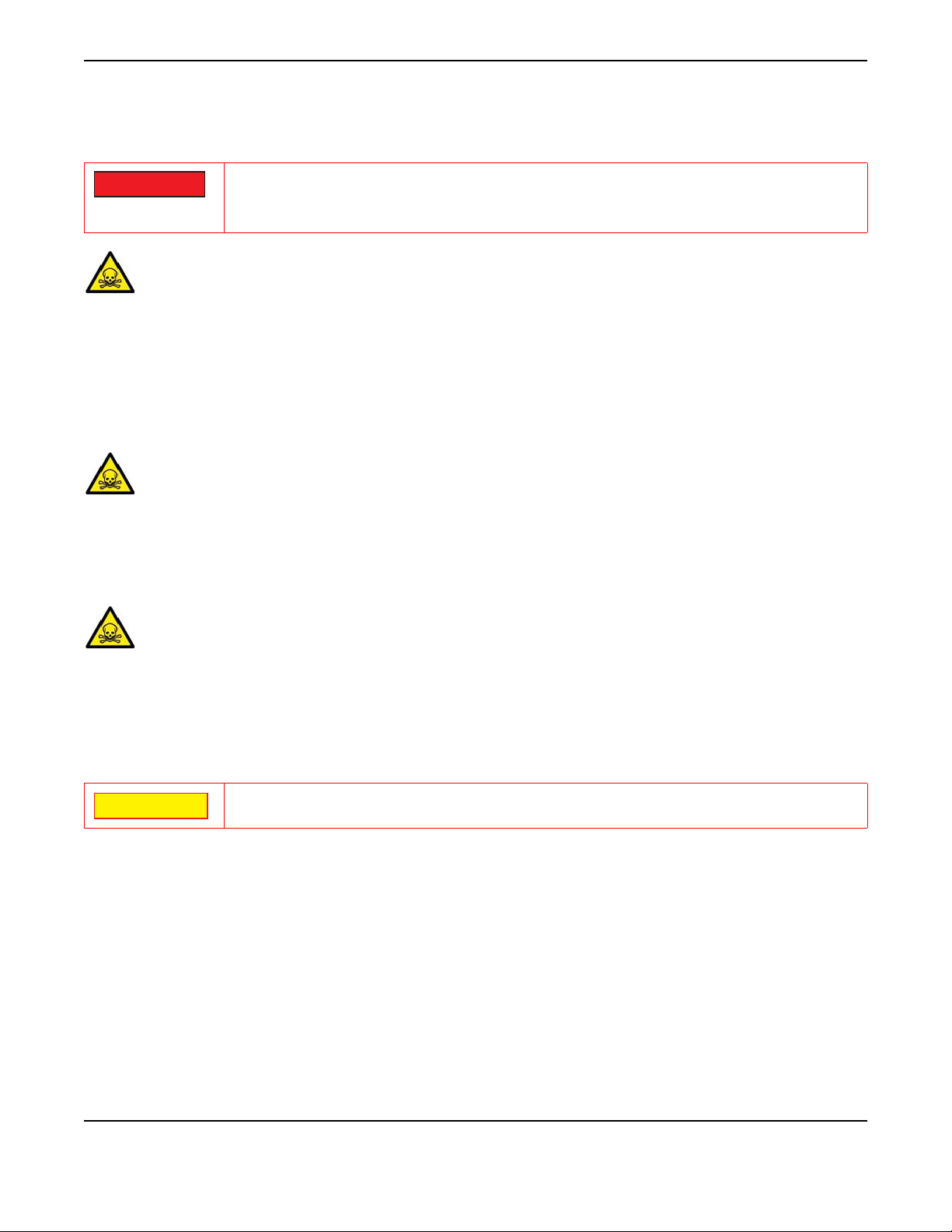
SAFETY FIRST - TO ALL OPERATIONS PERSONNEL (cont)
TOXIC HAZARDS
BERYLLIA
Beryllia (beryllium oxide) is used in the construction of some of the components in this equipment.
This material, when in the form of fine dust or vapor and inhaled into the lungs, can cause a respiratory
disease. In its solid form, as used here, it can be handled safely, however, avoid handling conditions
which promote dust formation by surface abrasion.
Use care when removing and disposing of these components. Do not put them in the general industrial
or domestic waste or dispatch them by post. They should be separately and securely packed and clearly
identified to show the nature of the hazard and then disposed of in a safe manner by an authorized toxic
waste contractor.
BERYLLIUM COPPER
Some mechanical components within this instrument are manufactured from beryllium copper. This is an
alloy with a beryllium content of approximately 5%. It represents no risk in normal use.
The material should not be machined, welded or subjected to any process where heat is involved.
It must be disposed of as “special waste.”
It must NOT be disposed of by incineration.
LITHIUM
A Lithium battery is used in this equipment.
Lithium is a toxic substance so the battery should in no circumstances be crushed, incinerated or
disposed of in normal waste.
Do not attempt to recharge this type of battery. Do not short circuit or force discharge since this might
cause the battery to vent, overheat or explode.
INPUT OVERLOAD
SOME OF THE COMPONENTS USED IN THIS EQUIPMENT MAY INCLUDE RESINS
AND OTHER MATERIALS WHICH GIVE OFF TOXIC FUMES IF INCINERATED.
TAKE APPROPRIATE PRECAUTIONS, THEREFORE, IN THE DISPOSAL OF THESE
ITEMS.
REFER TO PRODUCT SPECIFICATIONS FOR MAXIMUM INPUT RATING OF ANT
AND T/R CONNECTORS TO AVOID INPUT OVERLOAD.
WARNING
CAUTION

PRELIMINARY
Subject to Export Control, see Cover Page for details.
ix
Preface
SCOPE
This Manual contains instructions for maintaining the GPSG-1000.
ORGANIZATION
This manual is composed of the following chapters:
CHAPTER 1 - INTRODUCTION
Chapter contains general Test Set information and theory of operation.
CHAPTER 2 - TROUBLESHOOTING
Chapter contains system and module level troubleshooting procedures.
CHAPTER 3 - VERIFICATION/CALIBRATION PROCEDURES
Chapter describes system and module level verification and calibration procedures.
CHAPTER 4 - REMOVE/INSTALL PROCEDURES
Chapter contains procedures for removing and installing maintainable parts and
assemblies.
CHAPTER 5 - PARTS LIST
Chapter identifies customer serviceable parts and assemblies.
CHAPTER 6 - ASSEMBLY AND INTERCONNECT DRAWINGS
Chapter contains system level interconnect and assembly drawings.
APPENDIX A - PIN-OUT TABLES
Contains diagrams and pin identification for external connectors.
APPENDIX B - ABBREVIATIONS
Lists acronyms and terms used throughout manual.
APPENDIX C - TEST EQUIPMENT REQUIREMENTS
Lists equipment needed to perform verification and calibration procedures.
APPENDIX D - CONTROLS & CONNECTORS
Identifies front and rear panel controls and connectors.

PRELIMINARY
Preface
Subject to Export Control, see Cover Page for details.
x
THIS PAGE INTENTIONALLY LEFT BLANK.

PRELIMINARY
Subject to Export Control, see Cover Page for details.
1 - 1
Chapter 1 - Introduction
1.1 PRINCIPLES OF OPERATION
1.1.1 GPSG-1000
Control Panel Assembly
The Control Panel Assembly, provides On/Off, Home Buttons and Status LED’s.
Power Supply Assembly
The Power Supply Assembly is responsible for supplying power for module operation and
providing +5 Volt bias for applied power status.
Converter Assembly
The Converter Assembly provides the Test Set’s AF, RF and Modulated Output signals.
RF Combiner Assembly
The RF Combiner Assembly provides Signal Attenuation and 10MHz system reference.
PXI Backplane Assembly
The PXI Backplane Assembly routes electrical signals between the various system
assemblies.
Rear Panel Assembly
The Rear Panel Assembly provides access to Tests Set’s Input/Output connectors and AC
charger.
Satellite Simulation
The orbit parameters for each satellite are configurable in terms of the standard
Keplerian (almanac) elements. The almanac used for simulation may selected from a list,
maintained by a file management system. The files may obtained from the built in GPS
receiver, as a current almanac load or may be loaded from a USB flash drive in Yuma
.alm format.
The standard Keplerian elements (almanac) are used to calculate the enhanced Keplerian
Elements (ephemeris), which are in turn used to generate the satellite motion, and are
broadcast as part of the navigation message.
As almanac data is typically valid for several days, the GPSG-1000 does not update the
standard Keplerian (almanac) elements during the course of the simulation.

PRELIMINARY
Introduction
Subject to Export Control, see Cover Page for details.
1 - 2
The GPSG-1000 computes the enhanced Keplerian (ephemeris) elements by
extrapolation of the configured standard Keplerian (almanac) elements. Any enhanced
Keplerian elements not includedin the standard Keplerian elements are set to zero. The
GPSG-1000 generates updated enhanced Keplerian (ephemeris) elements at a fixed time
interval of 4 hours, this being the update rate supported by both GPS and Galileo.
The GPSG-1000 generates in real time the positions of all simulated Satellites i.e.
positions are not be pre-computed for the entire simulation run.
Satellite Selection
For each simulated GNSS system the GPSG-1000 will perform an independent satellite
selection process and if the total number of visible satellites exceeds the maximum
number of hardware channels allocated to that system, then the GPSG-1000 will select
those satellites which approximate the minimum DOP for that system. The GPSG-1000
updates its satellite selection every 60 minutes.
Note: In the case of the 6 channel GPSG-1000, with large numbers of simulated satellites
it becomes possible for many more satellites to be visible at the user location than there
are available hardware satellite channels. If this happens the GPSG-1000 allocates
channels on a 'best effort' basis but does allow the operator to override the selection
manually.
The GPSG-1000 allows the operator to manually replace any selected satellite with
another visible satellite from the same GNSS system, with the manually selected satellite
remaining selected until it is no longer visible, or until it is manually replaced. The
manually de-selected satellite will remain eligible for re-selection at the next automatic
update.
Other manuals for GPSG-1000
3
Table of contents


