AeroFlow AF9552-1102 User manual

40 Huntingwood Drive Huntingwood NSW 2148
Phone: (02) 8825 1999 Website: www.aeroflowperformance.com
INSTALLATION MANUAL
AEROFLOW PERFORMANCE
EXTERNAL WASTEGATE
WARNING!
BEFORE PROCEEDING WITH INSTALLATION PLEASE READ INSTRUCTIONS CAREFULLY. THIS PRODUCT REQUIRES
DETAILED KNOWLEDGE OF AUTOMOTIVE SYSTEMS. WE RECOMMEND THAT THIS INSTALLATION BE CARRIED
OUT BY A QUALIFIED AUTOMOTIVE TECHNICIAN.
Use caution when working on a hot engine. Wastegate and turbocharger components are EXTREMELY HOT
and can cause severe burns.
Fitting this wastegate may require fabrication or modification to your exhaust manifold.
This wastegate is designed for use with a turbocharger that does not have an internal wastegate.
Aeroflow Performance recommends that the engines Air/Fuel ratio is checked while setting the desired boost
pressure, as any increase in boost pressure can cause the engine to run “LEAN”, resulting in possible engine
damage.
Aeroflow Performance recommends that boost pressure is set using a dynamometer and not on public roads.
INTRODUCTION
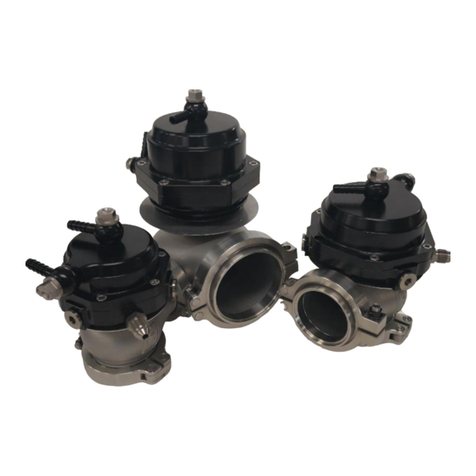
Congratulations on your purchase of Aeroflow Performance 44mm external wastegate. Aeroflow Performance
products cannot and will not be responsible for any damage, or other conditions resulting from misapplication
of the parts described herein. However, it is our intention to provide the best possible products for our
customer, products that perform properly and satisfy your expectations. Should you have any questions?
Please call technical support at +61 2 8825 1900 and have the product part number on hand when calling.
Aeroflow Performance wastegates are designed to control the turbochargers boost by bypassing turbine inlet
exhaust gas via a spring loaded valve diaphragm assembly. Spring rate, in conjunction with boost pressure
signal and back pressure, control the opening point of the wastegate valve. Once the spring rate has been
overcome, the valve will open. This causes exhaust flow to be diverted away from the turbine side of the
turbocharger, effectively slowing and/or stabilizing the turbines wheel speed. This stabilization results in a
smooth and steady boost pressure level, created by the compressor wheel of the turbocharger. Open pressure
of the valve can be controlled via spring rate and or a boost controller, such as a manual boost controller or an
electronic boost controller.

Aeroflow wastegates feature an internal valve constructed from high temp NICrFe based alloy. Other features
include a high temperature silicone nomex reinforced actuator diaphragm and stainless steel actuator springs
that delivers consistent boost pressure at high temperatures. Nitronic stainless steel is used for the valve seat
and valve bushing which all offer longer product life at extreme temperatures.
Aeroflow Performance wastegates feature water cooling ports ( 2 x M8x1.0mm ) for those heavy duty
applications. These are optional and can be disregarded if not required. There are also three lower air pressure
ports and two top air pressure ports ( 5 x M10x1.00mm ) for easy installation this eliminates the need to rotate
the actuator top hat, two stainless steel plugs and gaskets are included for unused lower air ports. Included in
the kit for the water cool ports are two stainless steel fittings and gaskets to a -4AN, for the air ports two
fittings and gaskets to -4AN both are stainless steel. Two banjo bolts in stainless steel and alloy banjo’s with
gaskets are included for a barb option to use a rubber/silicone 6mm vacuum hose.
Aeroflow Performance wastegates come pre-set to 1 bar ( 14.7 PSI ). This can easily be altered by purchasing
and installing springs from Aeroflow’s accessory spring range. The wastegate also includes required stainless
steel hardware for installation which includes : valve seat, inlet V-band clamp/flange and outlet V-band
clamp/flange.
INSTALLATION RECOMMENDATIONS
Be sure to install the valve seat into the body of the wastegate before final installation.
Tighten the supplied V-band clamp bolts to 10Nm ( do not overtighten )
In order to assure proper boost control, this wastegate needs to be mounted at a smooth transitional
angle with the exhaust flow. 90° mounting onto exhaust tubing is not recommended. The inlet fitting
should be welded to the exhaust manifold after all the exhaust runners have merged, and in a
position that promotes smooth flow to the wastegate –fast-moving exhaust gas is reluctant to make
sharp turns, which significantly reduces the flow potential through the wastegate.
Inlet and Outlet flanges are constructed of, 304 stainless steel and are compatible with most stainless
steel and mild steel welding rod material.
It is recommended to secure all vacuum and boost control hoses securely with zip ties or cushioned
clamps. Route all vacuum hoses away from high heat sources such as the turbine housing and exhaust
manifold. Aeroflow Performance recommends the use of braided lines and fittings for extra
protection against heat sources.
BOOST CONTROL RECOMMENDATIONS
There are many different ways to connect the wastegate boost ports. Whilst it is possible to use any number of
different methods that are not listed below, you should always remember the following:
-The lowest boost pressure possible is determined by the spring
-The lowest possible boost pressure for a given spring combination is achieved when the full boost
pressure is applied to the lower actuator port, and none to the upper port
-Boost pressure increases when you decrease the pressure at the lower port and/or Increase the
pressure at the upper port
For more information or technical enquires
Contact: Aeroflow Performance on
Phone: (02) 8825 1999 Website: www.aeroflowperformance.com

If no boost controller is being used connect the boost pressure source ( often found on a port
between cylinder head intake ports & throttle body ) to one of the bottom air ports on the wastegate.
The boost only pressure source should be sourced from as close to the compressor side of the turbo
as possible. This configuration results in a boost pressure that is dictated by the wastegate spring –
you must change the spring to alter the boost level you wish to run.
The unused upper actuator port should be left open to atmosphere, but if there is a chance that
containments could enter into the upper port, either remove and rotate the cap, or connect a short
length of hose to the nipple and route to a safe location.
If a manual boost controller is too be used follow the no boost control option and tee piece the boost
controller into the pressure hose from the bottom air port of the wastegate. This will allow the boost
to be easily increased above the base level. The controller does this by reducing the pressure getting
to the wastegate - the more the controller bleeds off, the higher the boost.
It is always recommended to consult the instructions of the brand manual boost controller you are
using.
If you are using an electronic boost controller with a mac valve you should consult your brands boost
controller instruction manual for specific information on how each of the ports of the solenoid valve
should be connected.
WASTEGATE SPRING SELECTION
The Aeroflow Performance wastegate has a variety of springs to suit different boost levels. Pre-installed with 1
Bar ( 14psi ). Different spring combinations may be required to suit different boost requirements and tuning
which are sold separately please refer to chart for more information on these springs. The tuner can use
combinations of up to 3 springs to achieve the base boost pressures required. To aid in the identification of
these springs they are colour coded. When selecting your spring rate, the total boost psi pressure is
determined by adding the spring rates together.
Wastegate spring selection will determine the minimum and maximum boost pressure that you want to run,
and your control method. Care should be taken when selecting boost pressures until the engine can be run on
a dyno to ensure safety. Always consult an expert when making boost changes, and it is recommended that
the car be checked on a dyno, as high boost and/or lean air/fuel mixtures can cause engine damage or worse,
total failure.
The lowest boost your car can run is determined by the spring installed, and boost can then be increased
through the use of a boost controller. It is recommended to select springs so that your maximum boost is no
more than double the spring that is installed into the wastegate. Whilst it is possible to increase boost beyond
this, you may find that boost becomes less stable and harder to control. This is because the boost controller
must bleed most of the control pressure signal to the actuator, so the wastegate is less able to self-correct for
changes in manifold pressure.
WARNING : It is recommended to reduce your boost controller back to its minimum setting, and monitor
your new minimum boost level with the new spring or springs, before increasing your boost pressure. Failure
to do so can lead to severe detonation and engine damage. Any damage incurred, as a result of detonation
from excessive high boost levels or improper installation is the customer’s responsibility. Aeroflow
Performance recommends that the air/fuel ratio be checked while setting the boost levels, as raising your
boost levels will change your air/fuel ratio of your tune up and could cause engine detonation or damage.
For more information or technical enquires
Contact: Aeroflow Performance on
Phone: (02) 8825 1999 Website: www.aeroflowperformance.com

CHANGING THE WASTEGATE SPRING
1. Remove boost pressure source hose from the wastegate as well as the breather hose if fitted.
2. Remove the wastegate from the exhaust manifold. Use CAUTION! The wastegate may still be HOT!
We recommend to allow the vehicle to cool down before attempting this spring change.
3. The use of a press or vice may be used to hold down the wastegate top cap while loosening the bolts
as the top cap is under the high spring tension. Ensure to use all safety gear necessary during this
procedure.
4. Using a 3mm hex allen key, remove the six hex key cap screws that secure the billet aluminium top to
the wastegate.
5. Remove the cap slowly, using care to secure the spring/springs upon removal.
6. Remove the spring/springs from the wastegate. Determine which spring/springs you will be installing.
A spring chart is located at the end of these instructions. Install the spring/springs into the wastegate,
on top of the diaphragm ensure they sit into the corresponding grooves in the wastegate. Use care to
ensure that you do not to tear or scratch the diaphragm.
7. Visually align the bolt holes of the top cap and wastegate base. Now compress the wastegate top cap
until it is seated with the wastegate base. Make sure that the bolt holes are aligned before tightening.
It may be necessary to rotate the wastegate top cap to align the bolt holes. If needed, relieve tension
on top, rotate and recompress. Once bolt holes are aligned, install the six 3mm hex head cap screws.
Tighten the cap screws in a criss-cross pattern to 6Nm.
WARNING : Make sure that the lip of the diaphragm is not pinched between the top cap and the
wastegate base
For more information or technical enquires
Contact: Aeroflow Performance on
Phone: (02) 8825 1999 Website: www.aeroflowperformance.com
This manual suits for next models
6
Table of contents
Other AeroFlow Industrial Equipment manuals

