aerosensor Aerodynamic Cycling System User manual

ACS Instructions V7.0 1
aerosensor
cycling
system
Instructions V7.0
ACS version 3.19
21.08.23

ACS Instructions V7.0 2
Contents
Important notes.....................................................................................................................4
aerosensor....................................................................................................................4
aerobody.......................................................................................................................4
aerodrome.....................................................................................................................4
Introduction...........................................................................................................................5
Prerequisites .....................................................................................................................5
Bike Computer...................................................................................................................5
Power Meter (PWR) ..........................................................................................................5
Speed (SPD) or Speed/Cadence (BSC) Sensor................................................................5
Device mounts...................................................................................................................5
aerosensor basics................................................................................................................6
Device specifications .....................................................................................................6
Layout............................................................................................................................6
Button functions.............................................................................................................6
LED significance............................................................................................................6
aerobody basics...................................................................................................................7
Device specifications .....................................................................................................7
Layout............................................................................................................................7
Button functions.............................................................................................................7
LED significance............................................................................................................7
aerodrome basics.................................................................................................................8
Device specifications .....................................................................................................8
Layout............................................................................................................................8
Button functions.............................................................................................................8
LED significance............................................................................................................8
aerosensor installation.........................................................................................................9
aerobody installation ..........................................................................................................10
aerodrome installation........................................................................................................11
Aerosensor Cycling System CIQ App Setup .......................................................................13
Garmin Connect IQ app...................................................................................................13
Installation.......................................................................................................................13
ACS general screen layout..............................................................................................13
aerosensor setup in CIQ app..........................................................................................14
Connection...................................................................................................................14
Pass-pairing.................................................................................................................14
aerosensor Parameters...............................................................................................15
Velodrome testing - Track layout..................................................................................17
Velodrome testing - Calculation mode..........................................................................18

ACS Instructions V7.0 3
aerosensor demo mode..............................................................................................19
aerosensor information ...............................................................................................19
aerobody setup ion CIQ app...........................................................................................20
Connection...................................................................................................................20
Set Reference..............................................................................................................20
Set Null Zone...............................................................................................................21
aerobody information...................................................................................................21
Riding with aerosensor.......................................................................................................22
General riding..................................................................................................................22
Out and back testing........................................................................................................22
How to test...................................................................................................................22
Calibration....................................................................................................................22
Velodrome testing ...........................................................................................................23
How to test...................................................................................................................23
Calibration....................................................................................................................23
Quick Start Checklist...........................................................................................................24
aerosensor .....................................................................................................................24
aerobody ........................................................................................................................24
aerodrome......................................................................................................................24
General aero testing tips .................................................................................................24
Aerodynamic basics............................................................................................................26
What is aerodynamic drag?.............................................................................................26
How do we measure aerodynamic drag?.........................................................................26
Why is aerodynamic drag important? ..............................................................................27
Testing................................................................................................................................28
Aerodynamic testing protocols & case studies.................................................................28
Overview......................................................................................................................28
Terminology.................................................................................................................28
Baseline control ...........................................................................................................28
Case studies....................................................................................................................29
Equipment....................................................................................................................29
Suggested Testing..............................................................Error! Bookmark not defined.

ACS Instructions V7.0 4
Important notes
aerosensor
aerosensor is designed for outdoor or velodrome use in dry conditions and is therefore not
suitable for wet conditions.
The device is not waterproof as by design it has pressure measurement holes.
aerosensor should be removed in wet conditions. If you think it will rain whilst you are out
riding or the road may be wet in places then take a 3mm hex key wit you so you can remove
the device and put it in your jersey pocket for the rest of your ride.
Clean aerosensor with a soft, dry cloth. Avoid using abrasive materials or harsh chemicals
that may damage the product's surface.
aerobody
aerobody uses optical sensors for measuring your body position, so keeping the sensor
lenses clean and free from debris is critical for good performance.
The USB port should be kept dry and free from debris. After charging, please ensure that the
bung is replaced firmly.
Although aerobody is splashproof, it is not designed to operate in wet conditions. Please
ensure it is removed if outdoors and raining.
Clean aerobody with a soft, dry cloth. Avoid using abrasive materials or harsh chemicals
that may damage the product's surface.
aerodrome
aerodrome uses a Tapeswitch cable as a lap trigger –the cable should not be pinched or
bent. Bending with a bend radius less than 4mm will permanently damage the product.
The USB port and Tapeswitch port should be kept dry and free from debris.
Although aerodrome is splashproof, it is not designed to operate in wet conditions. Please
ensure it is not used outdoors when it is raining.
Clean aerodrome with a soft, dry cloth. Avoid using abrasive materials or harsh chemicals
that may damage the product's surface.

ACS Instructions V7.0 5
Introduction
Congratulations on making the first step towards becoming your own aerodynamicist! This
guide outlines the key features of your new aerosensor Aerodynamic Cycling System.
Prerequisites
The aerosensor Aerodynamic Cycling System (ACS) encompasses the following 3 devices:
•aerosensor: real-time drag measurement device. Requires an ANT+ power and
either bike speed or bike speed + cadence sensor.
•aerobody: body position sensor. Does not require any other devices to work
•aerodrome: wireless lap trigger. Requires aerosensor device.
All devices require a Garmin cycling computer.
Bike Computer
Currently to use the ACS you will need a Garmin bike computer that can run Garmin
Connect IQ applications at a minimum of SDK 3.1.0. A full list of compatible devices is
available on the link below –be sure to check that the device has the “A” symbol, meaning
apps.
https://developer.garmin.com/connect-iq/compatible-devices/
We will make data fields in the future, allowing you to see data in the standard Garmin
context, and also on the Edge 130.
Power Meter (PWR)
aerosensor requires a quality power meter. Single sided pedal-based power meters are not
sufficiently accurate for good aerodynamic data. Remember that the aero data you get will
only be as accurate as the power meter used.
Speed (SPD) or Speed/Cadence (BSC) Sensor
Accurate speed measurements are critical for high accuracy data. This means using a
magnet-based speed sensor. Hub mounted speed sensors or GPS based speed sensors do
not have the time resolution necessary for high quality aerodynamic data.
Device mounts
aerosensor and aerobody have been designed to work on a variety of different bike bar
types, notably the following:
1. Drop handlebars –usually standard on road bikes and track bikes.
2. Clip-on time-trial (TT) bars –additions to road and track bikes.
3. Integrated TT handlebar/cockpit –mostly seen on TT and triathlon specific bikes.
Whilst aerosensor and aerobody can be used on most bike setups, there will be some bar
variants that may be trickier to setup. Please do not hesitate to contact us at
hello@aerosensor.tech with any questions or for advice on how to best mount onto your
bike.

ACS Instructions V7.0 6
aerosensor basics
Device specifications
Dimensions (H x W x D)
135 x 57 x 85mm
Mass
66g
Battery Life
57 hours
Wind speed resolution
+/- 0.1%
Wind angle resolution
+/- 0.1°
Altitude resolution
+/- 10cm
Layout
1. LED
2. Power button
3. Reset button
4. USB-C bung & charging port
5. Stem
6. Height/yaw adjustment screw
7. Go-pro mount
Button functions
•Power button:
oPress and release to turn on.
oPress and hold until LED turns off then release to shut down.
oPress and hold, push reset button, then release for full factory reset. This
resets the internal settings used to calculate CdA.
•Reset button:
oTo be used in case the device becomes unresponsive. Resets device without
erasing settings.
LED significance
The multi-colour LED indicates the device state as shown below:
Colour
Flashing
State
USB
Charge
Aqua
Normal
On
Unplugged
Normal
Red
Normal
On
Unplugged
Low
Amber
Slow
Off
Plugged in
Charging
Amber
Solid
On
Plugged in
Charging
Green
Slow
Off
Plugged in
Charged
Green
Solid
On
Plugged in
Charged
Note: Do not use sharp objects or tools to press buttons, this may result in damage.

ACS Instructions V7.0 7
aerobody basics
Device specifications
Dimensions (H x W x D)
36 x 32 x 64mm
Mass
37g
Battery Life
9 hours
Head position resolution
+/- 1mm
Chest position resolution
+/- 1mm
Layout
1. LED
2. Power button
3. Reset button
4. USB-C bung & charging port
5. Head sensor
6. Chest sensor
7. Quarter-turn mount
Button functions
•Power button:
oPress and release to turn on.
oPress and hold until LED turns off then release to shut down.
•Reset button:
oTo be used in case the device becomes unresponsive.
LED significance
The multi-colour LED indicates the device state as shown below:
Note: Do not use sharp objects or tools to press buttons, this may result in damage.
Colour
Flashing
State
USB
Charge
Aqua
Normal
On
Unplugged
Normal
Red
Normal
On
Unplugged
Low
Amber
Slow
Off
Plugged in
Charging
Amber
Solid
On
Plugged in
Charging
Green
Slow
Off
Plugged in
Charged
Green
Solid
On
Plugged in
Charged

ACS Instructions V7.0 8
aerodrome basics
Device specifications
Dimensions (H x W x D)
34 x 76 x 76mm
Mass
66g
Battery Life
28 hours
Timing resolution
+/- 1ms
Layout
1. Power button
2. LED
3. Reset button
4. USB-C charging port
5. Tapeswitch port
Button functions
•Power button:
oPress and release to turn on.
oPress and release to shut down.
•Reset button:
oTo be used in case the device becomes unresponsive.
LED significance
The multi-colour LED indicates the device state as shown below:
Colour
Flashing
State
USB
Charge
Cyan
Solid
On
Unplugged
Normal
Lilac
Solid
Trigger
N/A
N/A
Amber
Solid
On
Charger
Low
Green
Solid
Off
Charger
Charging
Blue
Solid
On
Computer
Charging
Light blue
Solid
Off
Computer
Charged
Any
Flash
On
Aerosensor connected
Note: Do not use sharp objects or tools to press buttons, this may result in damage.
ACS Instructions V7.0 9
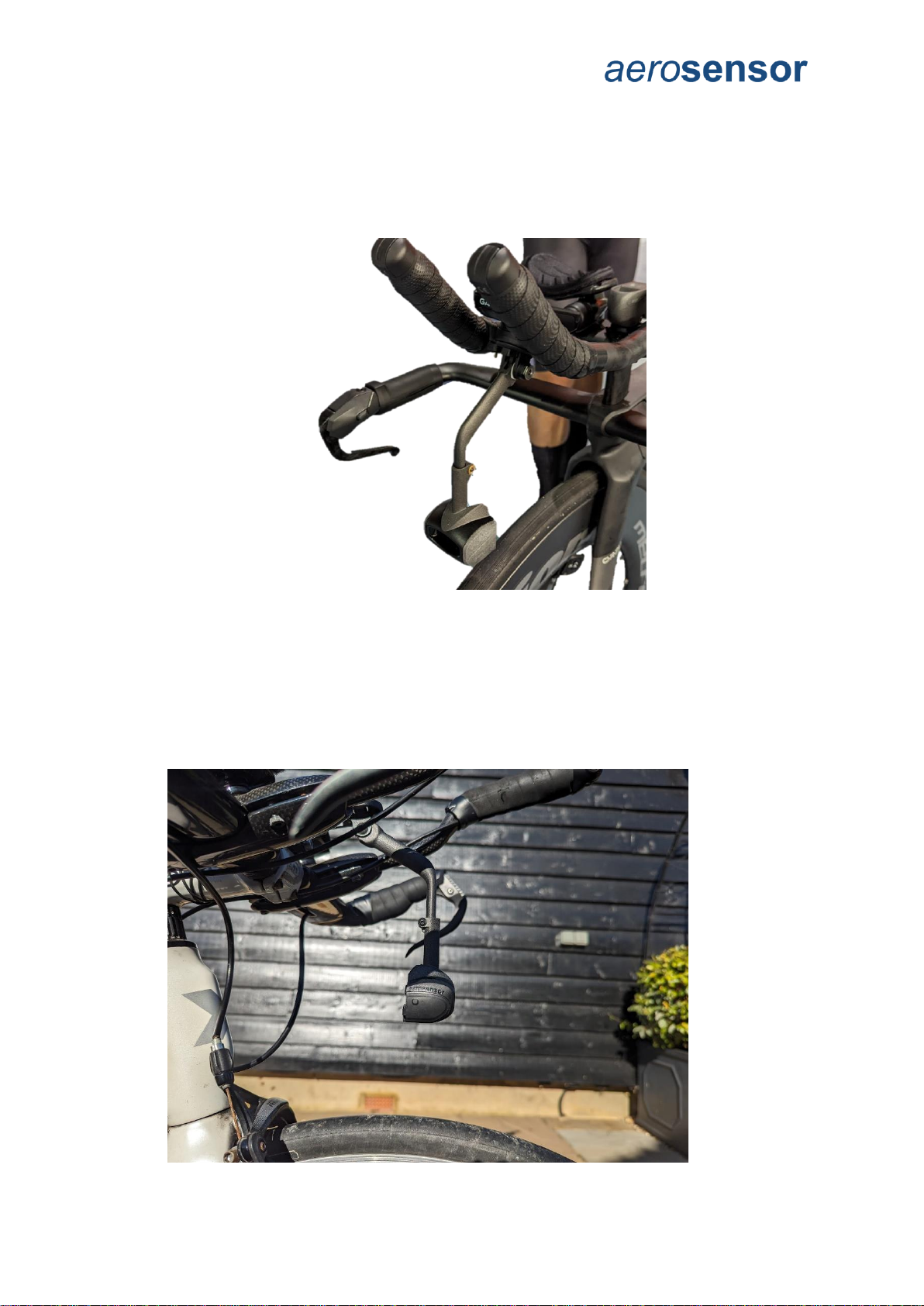
aerosensor installation
A go-pro mount is required to install aerosensor - for example one underneath a bike
computer mount (sold separately).
Use the go-pro mount itself to adjust pitch, then the yaw by loosening the height/yaw screw
on aerosensor’s stem (height adjuster) and rotating the unit.
When installing, it is important to have aerosensor as far forward and low as possible to
minimise influence of rider position.
•The base must be at least 20mm above the front wheel.
•It should be centred on the bike and facing forwards. Use the front wheel as a
reference for yaw alignment.
•aerosensor should be level - use a horizontal object to the side of the bike (like floor
markings), and visually align the bottom of Aerosensor with the horizontal line. An
example is shown below, where a horizontal line on the wall is used. Note that the
device is tolerant to pitch misalignment within +/-5°.

ACS Instructions V7.0 10
aerobody installation
aerobody has a standard Garmin quarter-turn mount. It should be positioned on the stem
using a compatible bike mount adapter such as the one supplied with the unit.
The screw on the quarter-turn mount allows pitch adjustment of the entire unit.
The forward (head) sensor should be aligned approximately with the chin and the chest
sensor points at the chest.
To align, support the bike either in a turbo trainer, or by asking someone to support the bike.
Sitting on the bike in your normal riding position watch the display whilst moving two fingers
up and down from your chin towards the unit, and ensure that the measurement tracks
movement of your fingers.
HEAD
SENSOR
CHEST
SENSOR
PITCH
ADJUSTMENT BOLT

ACS Instructions V7.0 11
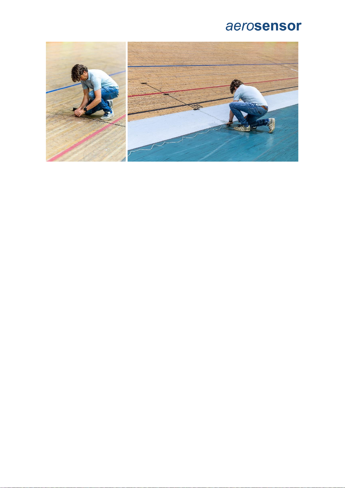
aerodrome installation
As aerodrome will likely be used on a live track or a public road, it is critical that you have
permission to use the device and/or have taken appropriate measures to ensure not only the
safety of you and other riders, but also to prolong the life of the device itself.
The tapeswitch should be placed so that the flat side is against the track or road, and the
ridge on the upper side. Using duck tape, secure the tapeswitch across the line the cyclist
will be following, be it on the track or the road. Secure at the far ends with tape, and placing
a further piece of tape along the length, just holding down the upstream side of the
tapeswitch.
Avoid taping across the ridge on the tape switch when taping along its length.
aerodrome listens for aerosensor and the LED flashes when it receives data. It is only able
to transmit the lap trigger when this is happening. Make sure aerodrome is situated in a
position where it can receive data from aerosensor when bike is at or just past the
Tapeswitch. It is normally best to position 1-2m downstream of where the lap trigger is
placed.
Plug the tapeswitch plug into the aerodrome socket and turn on. The power light should
illuminate. You can check it is working by pressing on the tapeswitch. The LED will turn
purple for 1 second to indicate a lap trigger.
aerodrome should be placed on the floor well clear of any area the rider is likely to pass.
Secure the tapeswitch cable to the floor with duck tape to avoid trip hazards.
Note that currently aerodrome cannot distinguish between multiple aerosensors
running on track. It will only work correctly when a single rider is on track.
Ridge
Duck tape along length of tapeswitch
Direction of travel
ACS Instructions V7.0 12

ACS Instructions V7.0 13
Aerosensor Cycling System CIQ App Setup
Garmin Connect IQ app
The aerosensor Aerodynamic Cycling System (ACS) Connect IQ app is required to
seamlessly integrate our devices with your Garmin bike computer, providing real-time
aerodynamic data and further insights during your ride, and recording your data to a FIT file
for further analysis.
Installation
1. The aerosensor ACS CIQ app can be download from the Garmin Connect IQ
website:
https://apps.garmin.com/
2. Simply search for “aerosensor” and the app will come up, or use this link:
https://apps.garmin.com/en-US/apps/0170243b-0384-4072-9e85-57030e4949a6
3. Install to the Garmin head unit as per the instructions on the CIQ app website.
4. Start ACS by going to the Connect IQ menu on your Garmin (see Garmin
instructions) and then selecting “aerosensor ACS”.
ACS general screen layout
1. FIT file recording status: Red square means not recording, green triangle means
recording.
2. aerobody connection and battery status.
3. aerosensor connection status.
4. aerosensor power and speed or speed/cadence sensor connection status. Green =
aerosensor connected to sensor; orange = searching; red = not connected.
5. aerosensor battery status.
6. Back key –in menus use to go back a step, or on data screens exists app.
7. Menu key.
The bottom-right button on the unit starts and stops FIT file logging.
Swiping left and right on the screen switches between data views.
ACS Instructions V7.0 14
aerosensor setup in CIQ app
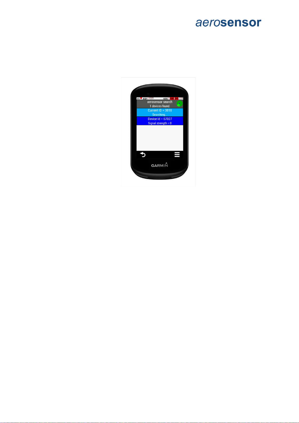
Connection
Make sure that aerosensor is switched on.
1. Press the menu button on the Garmin head unit.
2. Select “Connections” -> “aerosensor”.
3. Select the device you want to connect to. Note: it is worth keeping a note of the
Device ID for your aerosensor and aerobody for your records, especially if you are a
coach and have multiple devices for your riders.
Pass-pairing
Pass-pairing is where ACS transmits the power meter and speed sensor ANT+ connection
details to aerosensor, allowing it to connect to them directly.
For this to work the Garmin unit should already be paired with the ANT+ sensors you are
using.
Note that aerosensor requires a power meter (PWR) AND EITHER a speed sensor (SPD)
OR speed + cadence sensor (BSC).
The CIQ app should automatically pass on the sensor connections to aerosensor. In case
this does not work, or you have multiple sensors on the bike, follow these steps:
1. Ensure that a power meter and speed sensor are installed on the bike and paired
with the Garmin. Make sure they are on by rotating the wheel and/or pedals/crank,
depending on the power meter.
2. In the ACS menu, select “Connections”->”Pass pair” which will bring up the following
screen:

ACS Instructions V7.0 15
3. Either select the devices individually or select the bottom “Enter to sync” button in
purple above. After a short period, the status bar at the bottom of the screen should
go green to show aerosensor matches the Garmin device. aerosensor connection
status icons should go from red to green.
aerosensor Parameters
To accurately calculate aerodynamic drag, aerosensor requires some information about you
and your bike:
1. Aero device calibration: This accounts for the fact that the wind slows as it
approaches the bike, so the wind speed measured by aerosensor is always slower
than the air far upstream of the bike. Default value is 1.18. Typically we see values
beweeen 1.1 and 1.45.
2. Total mass (kg): includes rider + bike + all accessories used whilst riding with
aerosensor.
3. Wheel Circumference (mm). If unknown, you can go into the speed sensor settings
on the Garmin and you will find the wheel circumference in there once you have
ridden far enough for the Garmin to calibrate against GPS.
4. Power meter scaling: Default value is 1.0. If using pedals or crank we need to
account for drivetrain losses. A typical value would be 0.98, i.e. 2% drivetrain loss.
5. CTF calibration offset: Used for CTF power meters.
6. Time av period: This is the time period used by aerosensor to average the CdA
value, default is 30 seconds.
ACS Instructions V7.0 16
7. Reference Crr: Rolling resistance coefficient (used if known), default 0.004. For an
indoor velodrome you should use 0.002 (half the road value). You can find typical crr
values for a range of tyres at https://www.bicyclerollingresistance.com/
8. Valid speed min: minimum speed (kph) for valid CdA automatic lapping. The CdA
calculation is started when you go above this speed, and stopped when you slow
down below this speed. The device automatically creates laps for each CdA
measurement period.
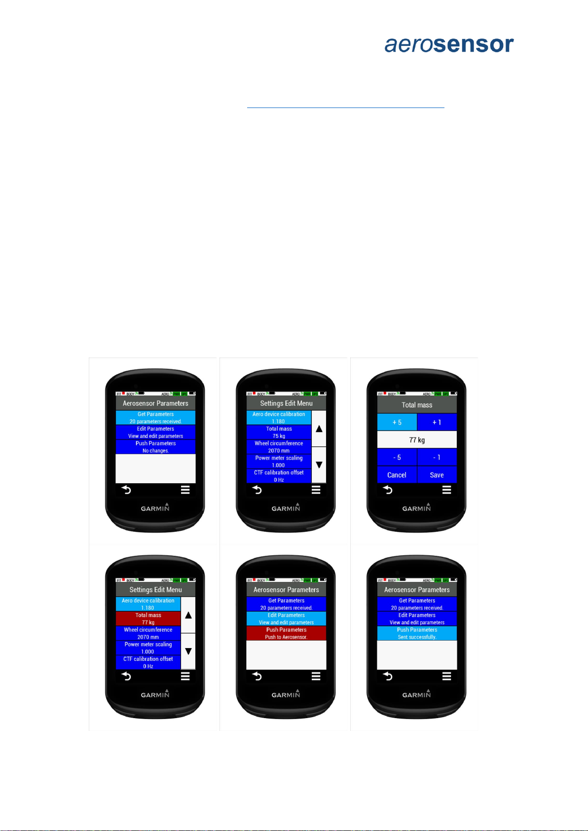
Editing Parameters:
The aerosensor device must be turned on and connected before taking the following steps.
1. Go to Menu-> aerosensor Settings-> aerosensor Parameters.
2. Ensure that the parameters have been received (“20 parameters received” under
“Get Layout” button header). If not, select “Get Parameter”.
3. Select “Edit parameters”.
4. Select setting to be edited on “Settings Edit Menu”.
5. Use buttons to edit value.
6. Click on “Save”.
7. On return to “Settings Edit Menu” note changed parameters shown in red.
8. Return to “aerosensor Parameters” menu.
9. Select “Push layout” to push settings to aerosensor. If successful, “Sent
successfully” will show.
Screen sequence shown below.
It is important you check these frequently, especially total mass and wheel circumference if
changing between bikes for example.

ACS Instructions V7.0 17
Velodrome testing - Track layout
When aerosensor is in track calculation mode it uses lap distance and speed to calculate
lean angle to compensate for centre of gravity location. This only works when aerodrome is
being used. A typical track layout is shown below, of which you can input the track
measurements by editing parameters directly in the CIQ app.
You can measure the track by measuring relative distance of corner start and end, using the
distance markers along the track. This does not need to be very accurate –within a few
meters is fine.
Steps to measure the track:
1. Measure the distance from the tapeswitch location to the start and end of each
corner.
2. Use these to calculate the total distance of the two straight sections.
3. Corner length = track length –total straight lengths
4. Corner radius = corner length / pi
5. Transition length is the distance it takes for the rider to transition from the straight to
the corner. Typical value is 10m.
Example:
Total track length = 250m.
Straight length = 60m (i.e. length of each individual straight = corner 2 start –corner
1 end + transition length
Corner length = (250 –60 –60) / 2 = 65 m
Corner radius = 130/pi = 20.7m
Editing Parameters:
1. Go to Menu-> aerosensor Settings->Track.
2. Ensure that the parameters have been received (“7 parameters received” under “Get
Layout” button header). If not, select “Get Layout”.
3. Select “Edit layout”.
4. Select setting to be edited on “Track Edit Menu”.
5. Use buttons to edit value.
6. Click on “Save”.
7. On return to “Track Edit Menu” note changed parameters shown in red.

ACS Instructions V7.0 18
8. Return to “aerosensor Track Layout” menu.
9. Select “Push layout” to push settings to aerosensor. If successful, “Sent
successfully” will show.
Screen sequence shown below.
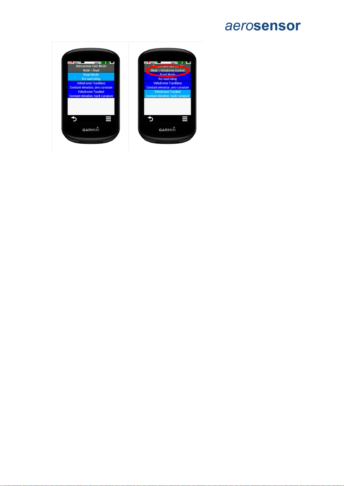
Velodrome testing - Calculation mode
At the velodrome aerosensor can ignore the barometer, since elevation is roughly constant,
and should use the track map. If the track map is not known, or aerodrome is not available,
you can use a trackless mode.
To use Velodrome mode:
1. Go to Menu-> aerosensor Settings->Calculation Mode.
2. Select the model you require:
a. “Road” mode is used for road riding.
b. “Velodrome Trackless” mode assumes constant elevation but ignores track
layout. This is for when you are not using a lap trigger (aerodrome) and the
track layout is unknown.
c. “Velodrome Tracked” mode assumes constant elevation AND uses the track
layout. This is for when you are using aerodrome and know the track layout,
as inputted in ‘aerosensor Settings->Track’.
3. Wait until the mode changes as required, in the menu heading.
Screen sequence shown below:
ACS Instructions V7.0 19
aerosensor demo mode
This is for diagnostic purposes and can generally be ignored.
aerosensor information
Got to Menu -> aerosensor settings -> about
Here you can see information about your aerosensor device, including battery level,
firmware version and serial number. Battery voltage is also included as it is useful for
diagnostic purposes.
ACS Instructions V7.0 20
aerobody setup ion CIQ app
Connection
Make sure that aerobody is switched on.
1. Press the menu button on the Garmin head unit.
2. Select “Connections” -> “aerobody”.
3. Select the device you want to connect to. Note: it is worth keeping a note of the
Device ID for your aerobody for your records, especially if you are a coach and have
multiple devices for your riders.
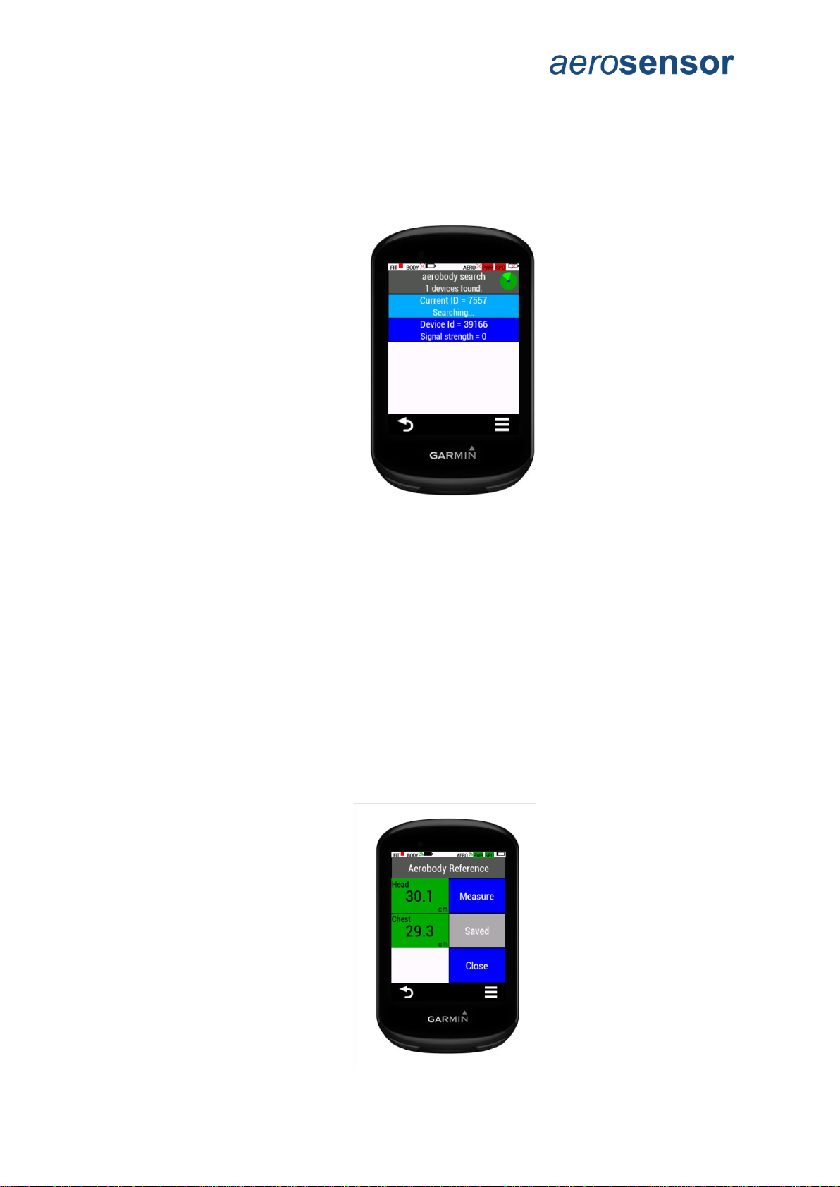
Set Reference
The CIQ app shows your body position relative to a reference which you can set as follows:
1. Got to Menu-> aerobody Settings->Set Reference.
2. Get into your ideal position on the bike. To do this support the bike in a turbo trainer,
or ask someone to support it for you, and get into your normal riding position.
3. Select “Measure”. This will give you a 5 second countdown to get in position, then
will take a 2 second average of your position. When complete the measurements will
show in red to indicate the new values are unsaved, and the “Save” button will be
highlighted.
4. Click “Save” to send the new position to aerobody. Wait for the head and chest
display to update to green, and the save button to turn grey and show “Saved”.
Table of contents
Other aerosensor Bicycle Accessories manuals


Popular Bicycle Accessories manuals by other brands

Bosch
Bosch Purion BUI215 Original operating instructions

by.schulz
by.schulz D.2 ST-Ri Installation and operating instructions

BOS Suspension
BOS Suspension IDYLLE user manual

Magicshine
Magicshine MONTEER 5000S user manual

Digital Telecom Technology Limited
Digital Telecom Technology Limited Elkfit Cycler C01 user manual

Asaklitt
Asaklitt 31-6100 manual


