by.schulz D.2 ST-Ri User manual

D.D.22
INSTALLATION + OPERATING INSTRUCTIONS
D.2 ST-Ri
www.byschulz.com
D.D.22
EN

2/20 Installation + Operating Instructions D.2 ST-Ri Seatpost
INTRODUCTION
Thank you for choosing a by,schulz product. Please read
these instructions carefully before assembly and use, and
keep them in a safe place. If you have any further ques-
tions about this product, please contact your dealer.
We wish you a safe ride!
TABLE OF CONTENTS Page
1. Usage approval 02
2. Safety instructions 02
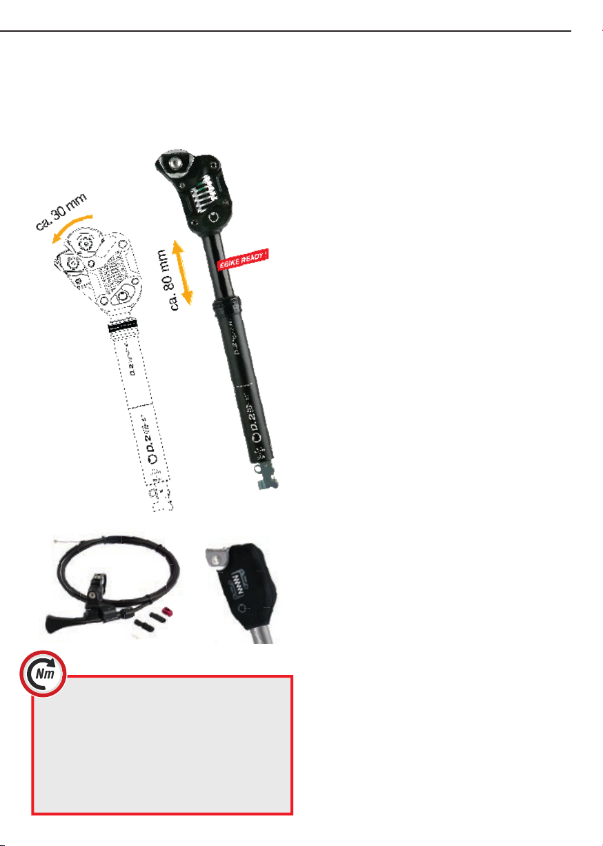
3. Scope of delivery 03
4. Function 03
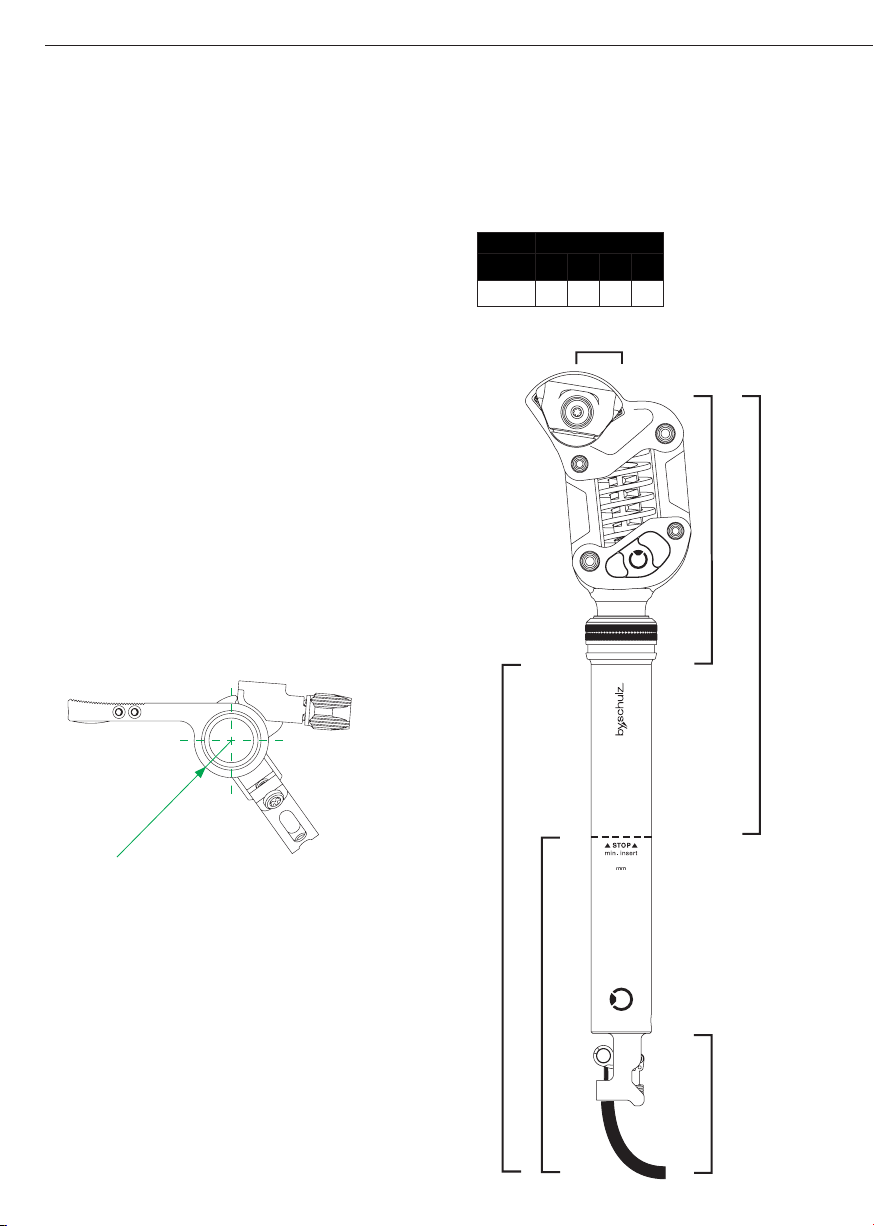
5. Technical Data 04-05
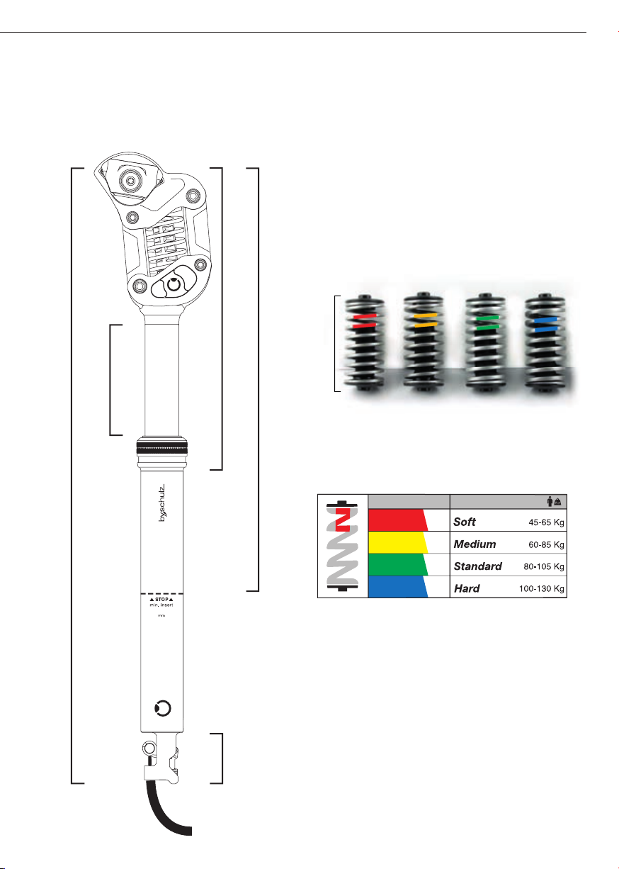
6. Spring elements 05
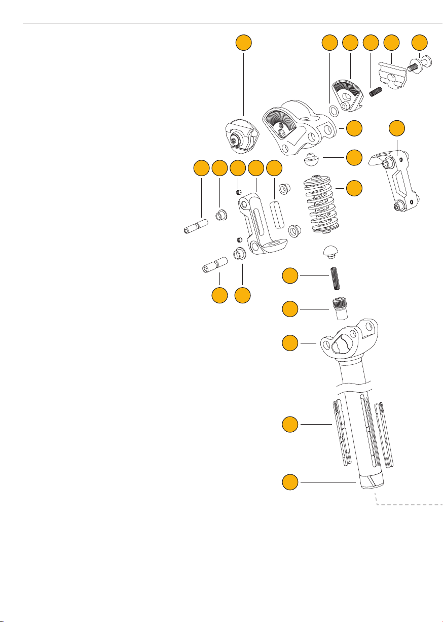
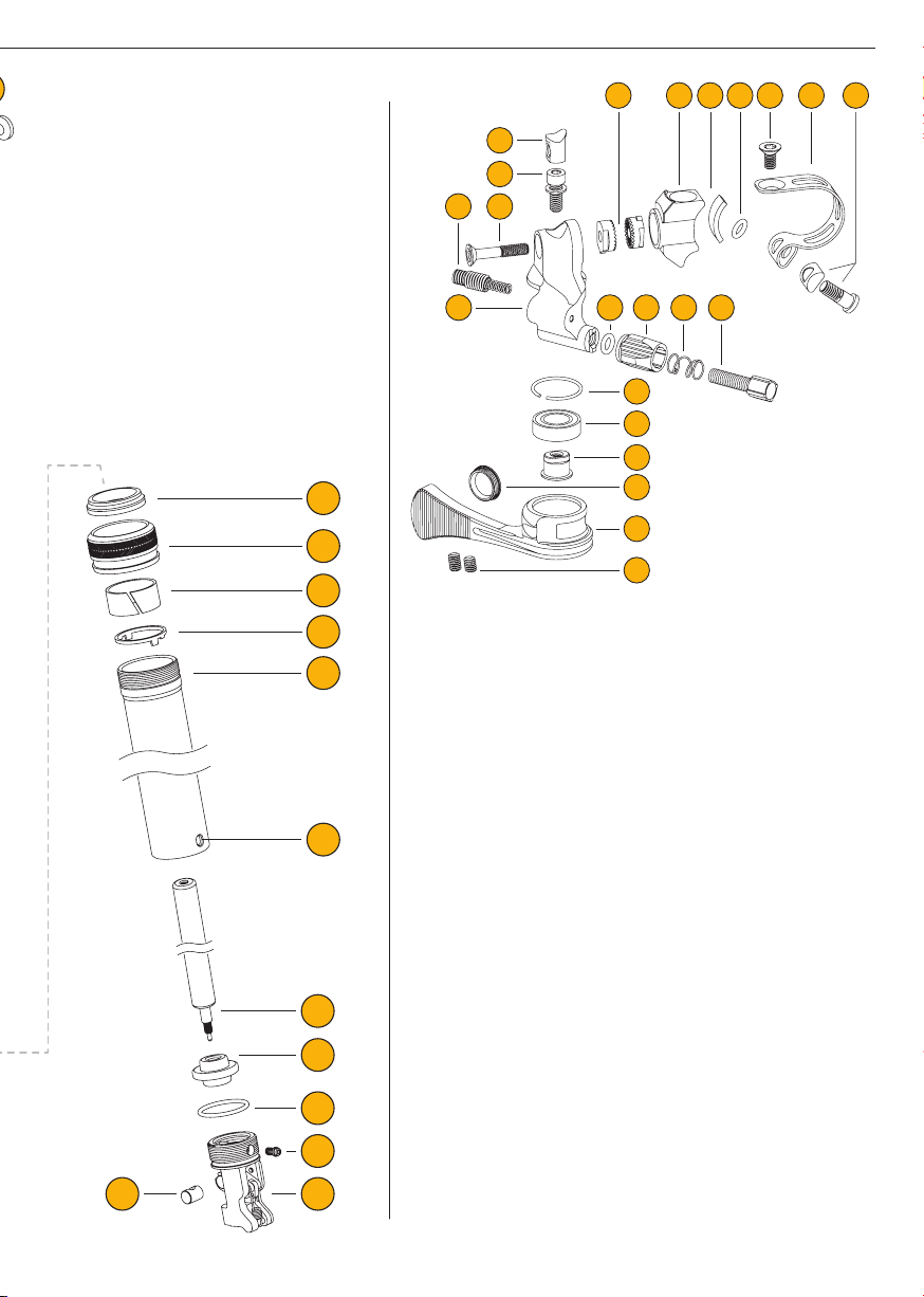
7. Seatpost components / Exploded view 06-07
8. Installation requirements 08-09
9. Installation 10-14
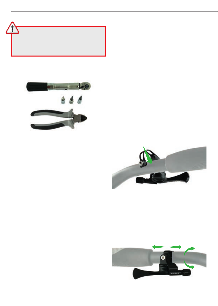
9.1 / 9.2 Tools + preparation 10
9.3 Mounting the remote lever 10-11
9.4 Routing the cable 12
9.5 Connecting seatpost + remote lever 12-14
9.6 / 9.7 Saddle installation / adjustments 15
10. Changing the spring element 16-17
11. Operating the seatpost 18
12. Care / Cleaning 18
13. Warranty / Guarantee 19
14. Maintenance / Service card 19
1. USAGE APPROVAL
The adjustable parallelogram suspension by,schulz D.2 ST-
Ri seatpost is for use with bicycles, cargo bikes, pedelecs
and e-bikes up to 45 km / h suitable. It is NOT designed
for extreme loads that occur during downhill, dual slalom
or freeriding, or for riding proles with jumps. The D.2 ST-
Ri seatpost is made of high-strength aluminium, and has
been tested and approved according to the following DIN
standards:
Before the rst ride:
We strongly recommend that you check the roadworthiness
of the bicycle in general, and the operational safety of the
seatpost in particular, before each ride.
First check that the saddle is rmly secured in the saddle
clamp. Also make sure that the seatpost tube is free of
play and rmly connected to the bicycle frame. It must be
clamped in the desired position in such a way that it cannot
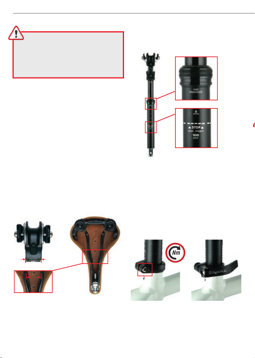
be turned or moved in the seat tube. Please note the mini-
mum insertion depth of the seatpost of 100mm.
2. SAFETY INSTRUCTIONS
1. These instructions contain important informa-
tion on the proper assembly, use and maintenance of
the by,schulz D.2 ST-Ri seatpost.Take the listed warning
and safety instructions seriously. Failure to do so may
result in property damage or personal injury, for which
neither the seller nor the manufacturer is liable.
2. Check the installation requirements before assembly.
If you do not have the necessary skills and / or tools, we
strongly recommend having the installation carried out
by a specialist dealer
3. Child seats, trailer couplings or luggage carriers must
not be attached to a D.2 ST-Ri seatpost as this can lead
to breakage or damage.
4. To avoid further risks of accidents after a fall with
damage, the seatpost must be checked and replaced
if necessary.
5. Always use the protective neoprene cover to cover
the spring mechanism if a child seat is mounted behind
the seatpost. Without the cover, there is a risk of injury
to children's hands!
6. The D.2 ST-Ri seatpost is not to be used for trans-
port with car bike racks where the bike is attached to the
saddle. Fastening to the seatpost may only be done as
shown in Fig. 2.1!
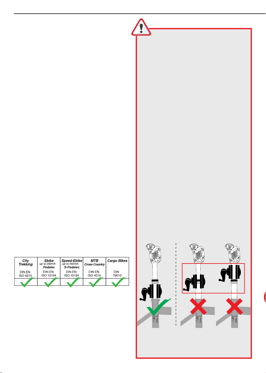
7. Clamping systems of mounting stands may only be
attached to the outer seatpost tube below the screw ring,
or to the frame of the bicycle. The inner seatpost tube
and the area of the screw ring are not suitable for this
purpose (Fig. 2.1).
Incorrect attachment can cause damage to the seat-
post, and void the warranty!
Fig. 2.1

3/20
Installation + Operating Instructions D.2 ST-Ri Seatpost
3. SCOPE OF DELIVERY
· D.2 ST-Ri seatpost incl. neoprene protective cover
· D.2 ST-Ri remote lever
· Inner cable with cable housing, end caps,
cable ttings and cable end sleeve
· Instruction manual
· Service card
4. FUNCTION
The D.2 ST-Ri combines the advantages of the by,schulz
D.1 dropper seatpost, with the maximum ride comfort of the
renowned G.2 parallelogram suspension seatpost with a
suspension of about 30mm in the ST variant (short travel).
Inside the drop down D.2 seatpost, a high-quality gas
pressure spring is installed. This allows to vary the saddle
height via a remote lever mounted on the handlebar! When
actuating the remote lever, the valve on the gas spring is
opened via an internal cable. As a result, the saddle is
lowered under load of the body weight, or raised when
relieved. When the lever is released, the valve closes and
the saddle remains at the current height.
By means of a remote lever mounted on the handlebars
the D.2 ST-Ri allows a comfortable lowering and raising
of the saddle position while riding or standing. This allows
you to individually adjust a perfect riding position. The low-
ering or raising of the saddle is triggered by operating the
remote lever. The saddle lowers down.
To lower the saddle height while riding, or when stopping
e.g. at a traffic light, keep your weight on the saddle and
operate the remote lever mounted on the handlebar.
To activate the seatpost extension, unload the saddle by
lifting your body and press the remote lever. The seatpost
now extends to the maximum height or stops and remains
in the current position when you release the lever.
The speed of this function can be controlled by the inten-
sity of the pressure on the remote lever. Little pressure
causes slow extension, strong pressure causes extension
at maximum speed.
The progressively designed parallelogram suspension
of the D.2 ST-Ri reacts sensitively to slight bumps, and
with increasing spring resistance to hard impacts. It dives
under load up to 18 mm to the rear, and about 22 mm
downward. For optimal adaptation to the rider's weight and
riding style, easily interchangeable spring elements with 4
different degrees of hardness and damping are available.
TIGHTENING TORQUE: This symbol re-
fers to an important screw connection that must be
tightened with an exact tightening torque. The cor-
rect tightening torque is either listed on the compo-
nent itself or in these operating instructions. A torque
wrench is required for execution! Screw connections
that are not tightened correctly can loosen or break
without warning.This can cause a fall or lead to prop-
erty damage and personal injury!

4/20 Installation + Operating Instructions D.2 ST-Ri Seatpost
5.1 TECHNICAL DATA
· Materials : Aluminium AL-6061, AL-6066, black anodized
· Cable routing : internal (Ri = remote inside)
· Suspension element : Length approx. 72mm
· Suspension travel : approx. 30mm
· Installation height retracted (dim. C) : approx. 135 mm
· Installation height extended (dim. H) : approx. 215 mm
· Offset : approx. 17 mm
· Rider weight : Ø 30,9 / Ø 31,6 : max. 115 kg
Ø 33,9 / Ø 34,9 : max. 130 kg
· Adjustment range / Travel (dim. G) : T80 = approx. 80 mm
· Bearing / linear guide : IGUS polymer high performance
plain bearing/ linear guide
· Diameter : Ø 30,9 | 31,6 | 33,9 | 34,9 mm
· Weight : approx. 965 g (Ø 30,9; T80 incl. medium spring)
· Suspension elements in 4 degrees of hardness for
adaptation to the rider's weight, easily exchangeable
· Saddle clamp Ø 7 mm with ne adjustment and robust
detent, optionally available for Ø 8 mm saddle rails
Remote lever D.1/D.2 Ri:
· Materials : Aluminium AL-6061, black anodized;
stainless steel, clamp band, black, screws; synthetic
components
· Clamping diameter : approx. 22,2 mm
· Lever radius : approx. 11 mm (Fig. 5.1)
· Weight : approx. 55 g
The D.2 ST-Ri seatpost is shipped with a remote lever
matching the seatpost model.You can recognize the
correct version by the imprint on the underside or lever
radius. (Fig. 5.1)
Cable routing:
· Cable housing: Jagwire approx. Ø 4,2 mm outside,
L = approx.1700 mm
· Shift cable / inner cable: Jagwire approx. Ø 1,2 mm,
L = approx. 1800 mm
Gas pressure spring:
Maintenance-free by,schulz gas spring
· Ø 30,9 / Ø 31,6 | T80: Housing Ø16,5; piston rod Ø6; M6
· Ø 33,9 / Ø 34,9 | T80: Housing Ø18; piston rod Ø6; M6
Dim. Dapprox. 225 mm
Dim. Capprox. 135 mm
Dim Bapprox. 190 mm
Dim. Aapprox. 280 mm
5.2 TECHNICAL DIMENSIONS
A - Max. installation depth incl. cable guide
B - Min. installation depth incl. cable guide
C - Min. retracted body height
D - Max. retracted body height
E - Installation space for Ri cable routing
Fig. 5.1
3 Nm D.1/D.2 Ri W-N-L-00001
R = approx. 11 mm
Ri
100
D.2
DROPPER
SU SPENSION
SEATPOST
ST
D.2
Dim. E approx. 90 mm
Available dimensions, Feb. 2023
Subject to change without notice.
x= rider weight up to 115kg
x= rider weight up to 130kg
Travel Ø D.2 ST-Ri
[mm] 30.9 31.6 33.9 34.9
T80 x x x x
Technical dimensions, as of Jan. 2023, subject to change at any time.
Fig. 5.2.1
Offset approx. 17 mm

5/20
Installation + Operating Instructions D.2 ST-Ri Seatpost
6. SPRING ELEMENTS
For the adjustable parallelogram suspension D.2 ST-Ri
seatpost, several spring elements with different char-
acteristics are offered, which can easily and quickly be
changed. Based on the following table, you can orient
yourself in the choice of the right suspension element,
whereby the criteria rider weight, riding position and riding
prole should be included in the decision.
For the D.2 ST-Ri, several suspension elements with differ-
ent spring settings are available: Soft, Medium, Standard,
and Hard for riders with a body weight from 45 to 130 kg
(see Table 5.2 Technical dimensions). The silver-colored
at wire steel springs with internal elastomer are marked
with a color code that shows their characteristics.
Length approx. 72mm
Basic color silver with color code
for hardness prole / driver weight
Maximum rider weight =
Weight of the rider + additional weight (e.g. backpack).
Only use the original by,schulz suspension elements for
the D.2 seatpost. The use of third-party parts can com-
promise the function of the seatpost and lead to accidents
with material damage or personal injury. In addition, this
will void the claims from liability for material defects and
warranty!
Dim. Happrox. 215 mm
Dim. Fapprox. 445 mm
Dim. Iapprox. 305 mm
Dim. Gapprox. 80 mm
Dim. Japprox. 40 mm
D.2
DROPPER
SU SPENSION
SEATPOST
ST
D.2
100
Ri
5.2 TECHNICAL DIMENSIONS
A - Max. installation depth incl. cable guide
B - Min. installation depth incl. cable guide
C - Min. retracted body height
D - Max. retracted body height
E - Installation space for Ri cable routing
F- Overall length
G- Adjustment range / travel
H- Min. extended body height
I - Max. extended body height
J- Ri Trigger unit
Available dimensions, Feb. 2023
Subject to change without notice.
x= rider weight up to 115kg
x= rider weight up to 130kg
Fig. 5.2.2
RED
GREEN
BLUE
YELLOW
COLORCODE HARDNESS GRADE

6/20 Installation + Operating Instructions D.2 ST-Ri Seatpost
Exploded view D.2 ST-Ri - as of Jan. 2023, subject to change without notice
7. SEATPOST COMPONENTS
SEAT CLAMP / forged Aluminium :
1. Seat clamp - assembled
1.1 O-Ring (2x)
1. 2 Seat clamp base for Ø7 saddle rails (2x)
1.3 Seat clamp pressure spring (2x)
1. 4 Seat clamp upper part for Ø7 saddle rails (2x)
1. 5 Seat clamp screw Torx T25 with washer (2x)
(optional: Allen key 5 mm)
HEAD / forged Aluminium :
2.1 Head base part with ne toothing
2.2 Elastomer recoil damper (2x)
SPRING ELEMENT :
3. Spring element consisting of:
- Flat wire steel spring
- Central elastomer damper
- Spring end-cap with centering pin (2x)
SPRING ARM / forged Aluminium :
4. Spring arm - assembled
4.1 Elastomer - stop damper (2x)
4.2 Spring arm with spring plate (2x)
4.3 Grub screw M5 (4x) - Allen key 2.5 mm (4x)
4.4 Small Igus plain bearing, inner Ø 6.5 mm, (4x)
4.5 Small stainless steel pin, outer Ø 6.5 mm, (2x)
4.6 Large stainless steel pin, outer Ø 8 mm, (2x)
4.7 Large Igus plain bearing, inner Ø 8 mm, (4x)
INNER TUBE / 3D forged Aluminium :
5.1 Gas spring screw M6x24; hexagon socket 3mm
5.2 Threaded sleeve; hexagon socket 7mm
5.3 Inner seatpost tube D.2 ST-Ri
5.4 by,schulz linear guide rails / IGUS (4x)
5.5 by,schulz slotted lower plain bearing / IGUS
OUTER TUBE / Aluminium :
6.1 Axial sealing ring
6.2 Ring nut with axial seal ring mount
6.3 by,schulz upper slotted plain bearing / IGUS
6.4 Stop ring / plastics
6.5 Outer seatpost tube with thread and
internal guide grooves
6.6 Slotted hole for xing screw
GAS PRESSURE SPRING :
7. 1 by,schulz gas pressure spring
7. 2 by,schulz elastomer stop damper D.2 ST-Ri
TRIGGERING MECHANICS Ri / Aluminium :
8.1 O-ring
8.2 Fixing screw M4x5,8; hexagon socket 2 mm
8.3 Release unit Ri
8.4 Cable retaining bolt
1
4.5 4.4 4.3 4.14.2
4
1.5
1.3 1.41.1 1.2
2.1
2.2
5.1
5.2
5.3
5.5
5.4
4.6 4.7
3

7/20
Installation + Operating Instructions D.2 ST-Ri Seatpost
DROPPER LEVER Ri / Aluminium
CLAMP BASE :
1. 1 Clamp with ne toothing (2x)
1. 2 Clamp base / Aluminium
1. 3 Adhesive elastomer pad
1. 4 O-ring
1. 5 Countersunk screw M4x8, Torx T20
1. 6 Clamp band / Stainless steel, black anodized
1. 7 Clamp screw with at head M5x14, Torx T20
with screw guide
LEVER BASE :
2.1 Cover
2.2 Cylinder head screw with washer
2.3 Countersunk screw M4x24, Torx T20
2.4 Stop adjustment screw M6 with compression spring,
hexagon socket 2.5 mm
2.5 Lever base Ri
2.6 O-ring
2.7 Adjusting sleeve
2.8 Compression spring for adjusting screw
2.9 Adjustment screw M5 for cable guide
REMOTE LEVER :
3.1 Snap ring
3.2 Industrial ball bearing
3.3 Counterholder ball bearing
3.4 Screw cap
3.5 Remote lever Ri / Aluminium
3.6 Grub screw M4x5 + M4x6, hexagon socket 2 mm
6.1
6.2
6.3
6.4
6.5
6.6
7.1
7.2
8.1
8.2
8.38.4
1.5 1.1 1.2 1.3 1.5 1.6 1.7
2.32.4
2.1
2.2
2.6 2.7 2.8
3.6
3.5
3.3
3.4
3.2
3.1
1.4
2.9
2.5

8/20 Installation + Operating Instructions D.2 ST-Ri Seatpost
8. INSTALLATION REQUIREMENTS
1. The by,schulz D.2 ST-Ri seatpost is designed for rout-
ing the cable housing inside of the frame. Not all bicycle
frames / e-bike frames are suitable for routing internal ca-
ble housing. An existing opening for the cable routing on
the frame is necessary.The cable routing must not be bent
or squeezed along its entire length! For e-bikes, it must
also be possible to route the cable along the battery and
the motor.
2. Before mounting, make sure that there is sufficient
space in the bicycle frame for the installation of the D.2
ST-Ri seatpost and that the seatpost does not collide with
other parts of the bicycle or bends in the frame geometry,
the battery or the motor!
3. Check that the width of the saddle rail is compatible with
the head of the seatpost. It must not be less than 35 mm
on the inside (Fig. 8.3.1). There are some saddles (e.g.
core leather saddles) that are too narrow in the front part
of the frame and therefore cannot be combined with this
seatpost.The use of the D.2 is not recommended as it can
permanently damage the saddle and the support.
min.
35mm
ca. 34mm
Fig. 8.3.1
4. The D.2 ST-Ri has a saddle clamp for round saddle rails
with a diameter of 7 mm as standard. If required, saddle
clamps for 8 mm diameter are available. Never combine
7 mm clamps with an 8 mm diameter saddle rail, or vice
versa. Saddles with oval saddle rails must not be used in
combination with the D.2!
5. Check if the minimum insertion depth of the seatpost of
100 mm can be maintained!
This is marked on the back of the seatpost tube (STOP
min. insert) below the extension scale. Above the scale
you will nd the production serial number (Fig. 8.5.1).
6. If the minimum insertion depth specied by the frame
manufacturer differs, this must also be taken into account.
The higher value is crucial. Failure to observe the mini-
mum insertion depth can lead to falls or damage to the
seatpost and/or the frame.
7. The clamping force of the seatpost clamp with bolts
should not exceed 5 - 6 Nm when xing the seatpost in
the frame. Use a torque wrench for this. (Fig. 8.7.1)
With a quick-release lever, the correct clamping force must
be determined by trial and error. It must not be possible to
push the D.2 into the frame or twist it. (Fig. 8.7.2)
max. 5 - 6 Nm
Fig. 8.7.1 Fig. 8.7.2
Exceeding the clamping force can lead to malfunctions
such as reduced extending or retracting speed and to
damage to components of the D.2 ST-Ri and must be
avoided.
NOTE: Plan the assembly as well as the cable
routing carefully. Make sure that the inner cable and
the housing are long enough for the planned instal-
lation route through the frame! Remove any burrs on
the seat tube of the bike.All parts must be clean for in-
stallation! Check before installation that the diameter
of the dropper post ts the diameter of the seat tube!
Serial Nr.
Min. insertion depth
Fig. 8.5.1

9/20
Installation + Operating Instructions D.2 ST-Ri Seatpost
Dimensions:
Dim. A- Min. installation retracted: ca. 135 mm
Dim. B- Min. installation height extended: ca. 215 mm
Dim. C- Max. required installation depth: ca. 230 mm
(plus cable)
Dim. D- Total length extended: ca. 445 mm
c
AB
C
D
Fig. 8.9.1 Fig. 8.9.2
9. Dimensions of the retracted and extended seatpost
NOTE: As a result of the parallelogram suspen-
sion, the D.2 ST-Ri has a greater installation height than
conventional dropper posts. Check these requirements
as accurately as possible in advance by measuring on
your bike. Also note that the individual height of your
saddle must be added for the correct seating position.
Regardless of the installation depth of the post, you
should still have a secure footing with your front foot
on the ground when the seatpost is fully lowered (Fig.
8.9.1)! If this is not the case, we advise against using
the support in combination with this bike.
8. The diameter of the seat tube of your bicycle / e-bike
should match that of the seatpost. Any reduction sleeves
required must have a minimum length of 100 mm and
must always be fully inserted into the frame.
If the frame manufacturer's specications differ with re-
gard to the sleeve length, these must also be taken into
account. The higher value is then crucial!
You can nd the by,schulz G.Shim reducing bushes at:
https://byschulz.com/product/g-shim-reducing-
sleeve/?lang=en
Double slotted sleeve
Ø 34,9 > 31,6
Ø 34,9 > 30,9
Ø 33,9 > 31,6
Ø 33,9 > 30,9
120mm

10/20 Installation + Operating Instructions D.2 ST-Ri Seatpost
Fig. 9.3.2
9. INSTALLATION
9.1 Tools
You will need the following tools and aids to install the
seatpost:
1. Torque wrench (2 - 20 Nm) with interchangeable bits:
Torx T20 / T25, hexagon socket 2 / 2.5 mm.
2. Bowden cable cutter, side cutter (optional)
3.Assembly grease (metal frame), or assembly paste (car-
bon frame) and cleaning agent
Optionally, a round le for removing sharp edges in the
seat tube of the frame, as well as pliers for tensioning the
inner cable, can be helpful.
9.2 Preparation
To be noted before assembly:
Measure and note the previously set saddle height. This
will make it easier for you to adjust the mounted D.2 ST-Ri
seatpost later. Remove the existing seatpost and saddle.
Clean the seat tube of the frame and check it for burrs.
If necessary, deburr the seat tube with e.g. a round le.
Only shorten the cable housing and the inner cable after
you have installed the parts for testing and checked the
cable length.
For frames made of metal, we strongly recommend that
you grease the inside of the upper part of the seat tube.
Any reduction sleeve used should also be greased. This
ensures smooth height adjustment of the seatpost later
on. Do NOT use grease on frames made of carbon bre
reinforced plastic (carbon). Use an assembly paste for
components and frames made of carbon instead.
With small bicycle frames or frames with bottle cage eye-
lets in particular, it is possible that the seatpost cannot be
inserted far enough into the seat tube of the bike. In this
case, the D.2 cannot be installed!
The remote lever of the by,schulz D.2 ST-Ri seatpost is
preferably designed for mounting on the left side of the
handlebar, but can be mounted on both sides. Locate a
good position on your handlebars. It may be necessary to
slightly move existing controls such as brake levers and
other attachments. The clamp usually ts under gearshift
indicators or controls. Afterwards, make sure that all con-
trols still work and are in a position that is easy for you to
reach.
9.3 Mounting the remote lever:
1. Slide the open clamp band onto the handlebar tube at
a good position. The handle does not have to be removed
for this. The O-ring on the open screw serves as an an-
ti-loss protection. Bend the clamp band by hand and screw
the M5 clamp screw lightly into the clamp base with a Torx
T20 tool so that the remote lever can still be positioned
later.
Fig. 9.3.1
The position and alignment of the clamp base, the lever
base and the remote lever can be adjusted in many ways
to suit your wishes and needs.
2. The clamp base can be positioned by moving it along
the handlebar or by rotating it around the handlebar tube.
(Fig. 9.3.2)
NOTE: All parts of the D.2 ST-Ri are technically
matched to each other. Only use an original by,schulz
remote lever. If products from other manufacturers
are used, the proper function of the D.2 ST-Ri dropper
post cannot be guaranteed!

11/20
Installation + Operating Instructions D.2 ST-Ri Seatpost
3. After you have nally chosen the position and alignment
of the clamp base, tighten the clamp screw rmly with the
Torx T20 tool and a torque of approx. 4 Nm. (Fig. 9.3.3)
T20
4. The position of the remote lever in relation to the han-
dlebar can be adjusted individually. To do this, loosen the
screw at the pivot point with a Torx T20 approx. 3 turns and
rotate the lever base to the desired position.
The ne toothing of the clamping pieces inside prevents
unintentional adjustment after tightening. After alignment,
tighten the screw rmly with a torque of approx. 3 Nm. (Fig.
9.3.4)
Fig. 9.3.4
T20
5. Screw the adjustment sleeve completely into the lever
base and then unscrew it by approx. 3 - 4 turns to allow
sufficient play for ne adjustment of the lever position later.
Unscrewing the adjustment sleeve tensions the inner ca-
ble, screwing it in relaxes the inner cable. (Fig. 9.3.5)
6. The remote lever can be positioned closer or further
away from the handlebar. If necessary, adjust the stop ad-
justment screw with a 2.5 mm hexagon socket by max. 6
turns counterclockwise. (Fig. 9.3.6)
2,5 mm
7. In order to be able to push the inner cable through,
loosen the two clamping screws on the underside of the
remote lever by approx. 3 turns using a 2 mm hexagon
socket. (Fig. 9.3.7)
Fig. 9.3.7
2 mm
8. Remove the screw cap from the lever using a very wide
screwdriver or other suitable tool. (Fig. 9.3.8)
Fig. 9.3.3
Fig. 9.3.6
Fig. 9.3.5 Fig. 9.3.8
NOTE: The adjustment of the adjusting screw
affects the pretension of the inner cable. You should
carry out this ne adjustment at the end of the as-
sembly. Finally, check the pretension and, if neces-
sary, adjust it by hand using the adjusting sleeve.

12/20 Installation + Operating Instructions D.2 ST-Ri Seatpost
9.4 Routing the cable
1. Starting at the handlebar, route the uncut cable housing
along the previously planned route through the frame to-
wards the seat tube.
When installing in an e-bike, make sure that the battery can
still be installed and removed and that the cable housing
can be routed past the motor. Make sure that the housing
protrudes approx. 30 mm from the seat tube of the bicycle,
that it can be moved freely by sliding, and that there are no
bends or squeezes. (Fig. 9.4.1)
Fig. 9.4.1
2. Now place the standard end cap on the cable housing
on the side of the seat tube. The housing should always
be inserted into the end cap as far as it will go. (Fig. 9.4.2)
Fig. 9.4.2
3. Feed the inner cable through the end cap into the cable
housing (Fig. 9.4.3) until it exits the housing on the handle-
bar side and the nipple of the cable end on the saddle side
still protrudes approx. 30 mm.
Fig. 9.4.3
9.5 Connecting seatpost and remote lever
1. Hang the tip of the cable into the red, slotted cable retain-
ing bolt (Fig. 9.5.1).
Pay attention to the bolt, as it is only loosely attached to the
inner cable and can easily fall off.
2. Insert the red cable retaining bolt with the mounted cable
into the actuator lever of the release mechanism. Then in-
sert the cable housing with the end cap into the cylindrical,
slotted socket provided for this purpose on the release unit.
(Fig. 9.5.2)
Fig. 9.5.1
Fig. 9.5.1
Fig. 9.5.2
3. Hold the cable slightly under tension so that it does not
unhook from the seatpost lever and push the D.2 ST-Ri into
the seat tube up to the previously determined seat height.
At the same time, pull the complete cable guide back to-
wards the handlebar (Fig. 9.5.3). Fix the height of the seat-
post by using the seatpost clamp (max. 6 Nm).
Fig. 9.5.3

13/20
Installation + Operating Instructions D.2 ST-Ri Seatpost
4. Hold the cable housing against the remote lever already
mounted on the handlebar and turn the handlebar 90° in
both directions.
The cable housing should make a slight curve in front of
the headset and allow the handlebars to be turned easily
in both directions. (Fig. 9.5.4)
5-6
Nm
5-6
Nm
NOTE: If an angle-adjustable stem or a handlebar
height adjustment system is installed, the length of the
cable guide must be adjusted accordingly!
5. Mark the cable housing to the correct length to shorten
it later. (Fig. 9.5.5)
Fig. 9.5.5
cable housing
6. As before, keep the cable slightly under tension! Open
the seat clamp and pull the seatpost out of the frame. At
the same time, push the entire cable guide back until it
protrudes approx. 30 mm from the seat tube. (Fig. 9.5.6)
Fig. 9.5.6
7. Pull the cable approx. 2/3 out of the cable housing and
shorten the housing to the previously marked length using
a high-quality side cutter. Make sure that the cable hous-
ing is not crushed at the cut edge so that the inner cable
can be pushed through without any problems.
8. Push the end cap onto the cable housing as far as it will
go. (Fig. 9.5.8)
Fig. 9.5.8
9. Push the cable through the shortened housing and the
end cap. As before in Fig 9.4.2, make sure that the exi-
ble end cap and cable housing are correctly seated in the
socket of the release mechanism. The cable should pro-
trude 150-200 mm from the cable housing.
Fig. 9.5.9
150-200 mm
cable
10. Keep the cable slightly under tension and push the
seatpost back into the frame at the same time as the cable
housing. Move the housing further towards the handlebar.
Make sure that the inner cable and the cable housing are
correctly seated on the release unit (Fig. 9.5.10). Fix the
seatpost at the desired seat height in the seat tube. After
the seatpost, cable housing and cable have been correctly
mounted in the frame, the cable should protrude from the
housing on the handlebar side.
Fig. 9.5.10
Fig. 9.5.4

14/20 Installation + Operating Instructions D.2 ST-Ri Seatpost
2 mm
11. Thread the inner cable through the adjustment screw of
the remote lever (Fig. 9.5.11.a).
Then insert it into the guide groove. (Fig. 9.5.11.b)
Fig. 9.5.11b
Finally, push the cable through the lever until it comes out of
the rear hole. (Fig. 9.5.11c).
Fig. 9.5.11c
12. Return the remote lever to its original position. Tension the
cable protruding from the lever by hand or with pliers.The end
cap of the cable housing must be seated in the adjustment
screw as far as possible. Fix the tensioned inner cable by
tightening both clamping screws on the underside of the re-
mote lever with a 2 mm hexagon socket to 3 Nm (Fig. 9.5.12).
2 mm
Fig. 9.5.12
13. Press the remote lever several times by hand. The cable
will be stretched and the cable hosing will settle slightly in the
socket. Now check the tension of the cable. If the tension is
not sufficient, loosen the clamping screws and retighten the
system. Fix the clamping screws again with the specied
torque. Operate the remote lever again several times and
check the function.
14. Push the ferrule, which is open on both sides, with the col-
lar rst onto the cable until it is completely seated in the hole in
the lever.Then crimp the ferrule tightly with pliers. Shorten the
cable directly behind the ferrule with a side cutter (Fig. 9.5.14).
The crimped ferrule prevents the cable from splicing.
Fig. 9.5.14
15. The shortened end of the cable should t completely into
the space under the screw cap. (Fig. 9.5.15)
Fig. 9.5.15
16. The cable end is then covered by tightening the screw
cap. (Fig. 9.5.16)
Fig. 9.5.16
Fig. 9.5.11a

15/20
Installation + Operating Instructions D.2 ST-Ri Seatpost
9.6 Saddle installation
1. Loosen the saddle clamp screw of the left and right saddle
clamp (Fig. 9.6.1) until the gap of the holding groove is ap-
prox. 9 mm (Fig. 9.6.2). When unscrewing the saddle clamp
screw, the saddle clamp opens by the pressure of the con-
cealed spring without twisting.
Fig. 9.6.1 Fig. 9.6.2
T25
2. Insert the saddle rail from above into the right or left hold-
ing groove of the saddle clamps (Fig. 9.6.3).
Fig. 9.6.3 Fig. 9.6.4
3. Then press the saddle rail into the groove of the opposite
saddle clamp (Fig. 9.6.4). A slight pressure point must be
overcome before the saddle frame audibly engages in the
saddle clamp.
4. Tighten the two saddle clamp bolts until the saddle frame
is loosely held in the saddle clamps. It should still be possible
to easily move the saddle lengthwise by hand and adjust the
angle in the detent of the saddle clamps.
9.7 Seat angle / seating position adjustments
1. The seat clamps and the head of the D.2 ST-Ri seatpost
are equipped with forged ne toothing. This allows you to in-
dividually adjust the desired saddle angle.You can also move
the saddle rail lengthwise in the seat clamp (Fig. 9.7.1). The
saddle rail must not be clamped in the curved area. Only
clamp in the straight area of the saddle rail!
2. Once you have determined your saddle position, tighten
the saddle clamping screws with a torque wrench in combi-
nation with a Torx T25 to a torque of 12 - 14 Nm (Fig. 9.7.3).
It is important to meet this value for safety reasons! The cor-
rect tightening torque is printed on both saddle clamps of the
support (Fig. 9.7.2).
3. To adjust the desired seat height, open the clamping
screw or the quick-release lever of the seatpost clamp on the
frame. Move the saddle to the desired position and retighten
the clamp to the specied tightening torque (max. 6 Nm) or
close the quick-release lever. (p. 8, Fig. 8.7.1 / 8.7.2)
4. The spring mechanism of the seatpost already com-
presses somewhat due to the load when sitting on the seat.
Therefore you can x the saddle approx. 10 mm higher to
compensate for this. Your specialist dealer will be happy to
advise you on this.
Riding direction
Fig. 9.7.1
NOTE : Ignoring the torques can lead to falls
can lead to falls, injuries and / or damage to in-
dividual components. Tighten the saddle clamp bolts
to the required torque after a short running-in period
of approx. 5 km, as well as during regular inspections!
ca. 9 mm
Fig.9.7.2
T25
Fig.9.7.3
The M6 Torx T25
saddle clamp screws
(optional 5mm hexa-
gon socket) must be
tightened to 12-14 Nm
with a torque wrench.
12 - 14 Nm

16/20 Installation + Operating Instructions D.2 ST-Ri Seatpost
10. CHANGING SPRING ELEMENT
10.1 Removal of the suspension
1. Unscrew the M5 grub screw on the lower, large bear-
ing in the rear arm of the D.2 ST-Ri seatpost using a 2.5
mm Allen key. Turn the screw counterclockwise until it pro-
trudes approx. 2 mm from the arm. Then use a suitable
tool to push the 8 mm stainless steel axle out of the bear-
ing. (s. Fig. 10.1.1)
2. After the axle is removed, open the parallelogram mech-
anism by pulling the rear spring arm up by hand. This will
cause the entire upper part of the seatpost to tilt forward
in the direction of travel. (see Fig. 10.1.2).
3. Swing the rear spring arm upwards in the small head
joint until the spring element is released from the adjust-
ment in the spring plate. Now you can remove the spring
element by hand. (see Fig. 10.1.3).
Use this opportunity to check the condition of the elasto-
mer damper elements in the seatpost base, spring arms
and head of the D.2 ST-Ri and, if necessary, to clean the
inner area of the spring element mount!
NOTE: The D.2 ST-Ri seatpost can remain mount-
ed in the bicycle frame to change the spring, also the
saddle does not have to be removed for this purpose!
We generally recommend using the Mudcover ST to
prevent soiling of the spring mechanism.
Fig. 10.1.1
Fig. 10.1.2
Fig. 10.1.3
stainless steel axle
grub screw

17/20
Installation + Operating Instructions D.2 ST-Ri Seatpost
10.2 Installation of the spring element
1. Place the original D.2 ST-Ri spring element in the par-
allelogram mechanism by hand. Press the spring element
into the recess provided in the spring arm plate. (see Fig.
10.2.1).
2. Now swivel the rear spring arm downward to make the
adjustment of the spring element between the arms. The
centering pin of the spring element engages audibly in the
recess of the spring arm plate. (see Fig. 10.2.2).
3. Fold the entire parallelogram mechanism including
the spring element back into the initial position. Now re-
insert the axle. Make sure that the axis is correctly guid-
ed through all holes and is ush on both sides. The grub
screw that xes the axis must be secured with medi-
um-strength screw adhesive. Screw in the M5 grub screw
and tighten it rmly with a torque wrench and a tightening
torque of 2.5 Nm. Before the rst ride with the new spring,
check the correct t of all components. (see Fig. 10.2.3)
Fig. 10.2.2
Fig. 10.2.1
Fig. 10.2.3
centering pin

18/20 Installation + Operating Instructions D.2 ST-Ri Seatpost
11. OPERATING THE SEATPOST
Finally, check the functions of the D.2 ST-Ri seatpost.
While sitting on the saddle, operate the remote lever until
the saddle starts to lower. Lower the saddle to the mini-
mum height by loading it with your body weight. The built-
in shock absorber provides a soft end stop. As soon as
you release the lever, the lowering of the saddle should
be interrupted.To have the saddle extend to the maximum
position again, operate the remote lever again and com-
pletely unload the saddle. Release the lever to x the po-
sition of the seatpost.
If the function cannot be performed as desired, check
the tension of the inner cable and the routing of the cable
housing. Make sure that the cable is correctly mounted on
the seatpost and the remote lever!
If the saddle lowers under load without the remote lever
being operated, the cable is probably under too much ten-
sion. This leads to the the valve of the gas pressure spring
not closing completely and the seatpost not being locked.
If necessary, reduce the pretension of the cable until the
dropper function of the seatpost no longer releases unin-
tentionally.
With the saddle clamp closed the outer tube of the D.2 ST-
Ri seatpost must not slip into the seat tube of the frame
under load, or be able to twist in it! If this is the case, check
the clamping force of the saddle clamp (max. 6 Nm).
12. CARE / CLEANING
To ensure proper function and longevity, cleaning and care
of the D.2 ST-Ri seatpost should be performed regularly.
Keep the parallelogram mechanism of the D.2 ST-Ri seat-
post and the bearings free of dirt and clean them regular-
ly. The protective Neoprene Mudcover effectively prevents
contamination of the mechanism (mud, sand, etc.), and
thus ensures a low maintenance. We recommend perma-
nent use of the neoprene cover.
If necessary, remove any dirt adhering to the outside,
especially from the inner tube of the seatpost, as this is
immersed in the outer tube. Stubborn dirt can damage
the surface of the post, the rubber seals, and bearings
installed inside.
As a rule, they can be removed with warm water and com-
mercially available detergents. Do not use steam cleaners
or harsh cleaning agents such as acetone, trichloroeth-
ylene or methylene for cleaning, as these cleaning agents
can attack the components, elastomers and bearings. For
maintenance, apply Rockshox Deo, for example.
When cleaning the D.2 ST-Ri seatpost, look for damage,
deformation or other changes to the components. If ques-
tions arise regarding the operational safety, your dealer
will be happy to advise you!
NOTE: The clamping force of the seatpost clamp
should not exceed 6 Nm when xing the post in the
frame (page 8, Fig. 8.3.1). Higher values can lead to
malfunctions such as reduced extending or retracting
speed and damage to components of the D.2 ST-Ri.
CAUTION: The installed gas strut is under high pres-
sure inside. Any manipulation of the gas pressure spring
can lead to serious injuries. Never attempt to open the gas
pressure spring!

19/20
Installation + Operating Instructions D.2 ST-Ri Seatpost
13. WARRANTY / GUARANTEE
The following conditions, which describe the prerequisites
and scope of our warranty service, do not affect the war-
ranty obligations of the seller under the purchase contract
with the end user. For the processing of a warranty claim,
the purchase receipt with the date of purchase and deliv-
ery must be submitted in each case.
A warranty obligation is not triggered by minor deviations
from the target condition, which are insignicant for the
value and usability of the product.
Please keep the proof of purchase.Your dealer or source
of supply is the contact person in the event of a complaint.
For the by,schulz seatpost type D.2 ST-Ri we provide war-
ranty according to the following conditions / points:
1. We will remedy defects free of charge according to the
conditions which are demonstrably based on a material
and/or manufacturing defect, if these are reported to the
rst end user immediately after detection and within 24
months after delivery. If the defect becomes apparent
within 6 months of delivery, it shall be presumed to be a
material or manufacturing defect.
2. No guarantee can be given if the defects in the product
are due to transport damage for which we are not respon-
sible, improper assembly, misuse, abnormal use, lack of
maintenance or care or failure to observe operating or as-
sembly instructions. Excluded are damages and their con-
sequences caused by improper assembly, modication of
the original parts, accidents, overloading (downhill, jumps,
competitions etc.).
3. The person who mounts the by,schulz D.2 ST-Ri seat-
post bears full responsibility for the mounting, compatibili-
ty and condition of the mounting parts.The warranty claim
expires if repairs or interventions are carried out by per-
sons who do not have sufficient professional knowledge or
if our product is provided with spare parts, supplementary
parts or accessories that are not original parts and thus
cause a defect. 4.
4. In the event of a warranty claim, if we refuse or fail to
remedy the defect, a replacement of equal value will be
delivered free of charge within the above-mentioned pe-
riod.
5. Warranty services do not cause an extension of the
warranty period, nor do they set a new warranty period in
motion. The warranty period for installed spare parts ends
with the warranty period for the product.
6. Further or other claims, damages caused by misuse
are excluded - as far as a liability is not mandatory by law.
7. These warranty conditions apply to products purchased
in Germany. For by,schulz products purchased abroad,
the warranty conditions issued by our respective country
representative shall apply. These can be requested from
the dealer from whom you purchased the product.
14. MAINTENANCE / SERVICE CARD
The by,schulz D.2 ST-Ri is a closed system.
Maintenance may only be carried out by the specialist
dealer, preferably by the by,schulz maintenance service!
The rst maintenance should be carried out after 12
months or after approx. 1,000 km, then annually or
approx. every 2,500 km. For this purpose, please send
the support together with the completely lled out service
card, as well as a copy of the purchase receipt, after prior
consultation, to:
by,schulz GmbH
Bühler Street 121, D-66130 Saarbrücken, Germany
GERMANY
To keep the warranty, the rst service of the D.2 ST-Ri is
obligatory. Within Europe you only have to pay the costs
for this. Customers outside Europe please contact the re-
gional sales partner!
www.byschulz.com
SK-D.2 Ri-20230108-DE / AN-12308-SK
by,schulz© 2023 Nachdrucke, Übersetzung und Vervielfältigung jedwederAr t, auch auszugsweisesind
ohne vorherige schriftliche Genehmigung ausdrücklich nicht erlaubt. Technische Änderungen, Irrtümer
sowie Druckfehler vorbehalten.Verwendete Abbildungen können vomOriginal-Produkt abweichen.
SERVICEKARTE
Montage-Anleitung
zum Downloaden:
www.byschulz.com
Montage-Videos
finden Sie unter:
www.youtube.com
by,schulz GmbH
Bühler Straße 121
66130 Saarbrücken
Germany
Tel : +49(0)681-59 59 81 18
Fax : +49(0)681- 59 59 81 19
www.byschulz.com
Sattelstützen Übersicht GOLD
WINNER
AWARD 2018
Datum:
Diese Stütze wurde verpackt von:
MODEL: [mm]
30.9
31.6
33.9
34.9
T80
Ri
Ro
Cable Set
Remote
Lever Travel
Ø

www.byschulz.com
www.youtube.com
by,schulz © 2023 No reprints, translations or copies of any kind allowed without the prior written approval of by.schulz GmbH. Subject
to technical alterations, errors and misprints excepted. Used photos can vary from the original product. by,schulz GmbH, Saarbrücken/
Germany M-D2 Ri-20230309-EN / AN-12308
by,schulz GmbH
Bühler Straße 121
66130 Saarbrücken
Germany
Tel : +49(0)681-95 97 25 0
Fax : +49(0)681-95 97 25 20
info@byschulz.com
www.byschulz.com
Operating instructions
available for downloald:
Installation videos
available under :
Table of contents
Other by.schulz Bicycle Accessories manuals

by.schulz
by.schulz Stem Alpha +10 SDS Installation instructions

by.schulz
by.schulz D.1 Ri User manual

by.schulz
by.schulz D.2 ST-Ro User manual

by.schulz
by.schulz Stem Alpha 35 SDS Installation instructions

by.schulz
by.schulz e-Bikelifter BM-60 User manual

by.schulz
by.schulz M.1 User manual

by.schulz
by.schulz Speedlifter 640119 User manual

by.schulz
by.schulz G.2 ST User manual

by.schulz
by.schulz G.2 ST Manual

by.schulz
by.schulz 650123 User manual