TECNOMAGNETE MaxX 125 User manual

PERMANENT – ELECTRO MAGNETIC SYSTEMS
U
US
SE
E
A
AN
ND
D
M
MA
AI
IN
NT
TE
EN
NA
AN
NC
CE
E
M
MA
AN
NU
UA
AL
L
L
Li
ig
gh
ht
t
D
Du
ut
ty
y
L
Li
if
ft
ti
in
ng
g
D
Di
iv
vi
is
si
io
on
n
h
ha
an
nd
d
c
co
on
nt
tr
ro
ol
ll
le
ed
d
l
li
if
ft
te
er
rs
s
-
-
M
Ma
ax
xX
X
TRANSLATION OF THE ORIGINAL INSTRUCTIONS
according to LEGISLATION 2006/42/EC concerning machinery
Lainate (MI) - Italy
Edition: May 2019
code 09MAXX001
version EN
revisione 01

2
codice 09MAXX001
versione EN
revisione 01
Use and Maintenance Manual
MaxX
CONTENTS
1 GENERAL NOTES ..................................................................................................................................................... 4
1.1 PRESENTATION ...................................................................................................................................... 4
1.2 IMPORTANCE OF THE MANUAL .................................................................................................................. 4
1.3 RETENTION OF THE MANUAL .................................................................................................................... 4
1.4 CONVENTIONS....................................................................................................................................... 4
1.5 DEFINITION OF SYMBOLS ......................................................................................................................... 5
1.6 PERSONNEL ASSIGNED TO OPERATIONS....................................................................................................... 5
1.7 TRAINED PERSONNEL .............................................................................................................................. 5
1.8 PERSONAL PROTECTIVE EQUIPMENT (PPE) ................................................................................................. 6
1.9 GENERAL SAFETY WARNINGS .................................................................................................................... 6
1.10 EMERGENCY DRILL.................................................................................................................................. 6
1.11 UNINTENDED OR IMPROPER USE ............................................................................................................... 6
1.12 NAMEPLATE DATA .................................................................................................................................. 7
2 TRANSPORT AND HANDLING.................................................................................................................................. 7
2.1 RECEIPT ............................................................................................................................................... 7
2.2 HANDLING ............................................................................................................................................ 7
2.3 TRANSPORT .......................................................................................................................................... 8
2.4 INACTIVITY............................................................................................................................................ 8
3 DESCRITPION OF THE SYSTEM ................................................................................................................................ 8
3.1 ADVANTAGES ........................................................................................................................................ 8
3.2 BASIC PRINCIPLES OF MAGNETIC CLAMPING WITH MAXX ............................................................................... 9
3.2.1. AIR GAP AND ROUGHNESS ..................................................................................................................... 10
3.2.2 CONTACT SURFACE ............................................................................................................................... 10
3.2.3 TYPE OF MATERIAL ............................................................................................................................... 10
3.2.4 MATERIAL THICKNESS ........................................................................................................................... 10
3.3 MAGNETIC FORCE ................................................................................................................................ 11
4 MODELS AVAILABLE ............................................................................................................................................. 11
4.1 MAXX ........................................................................................... ERRORE. IL SEGNALIBRO NON È DEFINITO.
5 TECHNICAL CHARACTERISTICS .............................................................................................................................. 12
5.1 MAXX TECHNICAL CHARACTERISTICS .............................................................................................. 12
5.2 MAXX DIMENSIONS AND WEIGHTS .......................................................................................................... 13
6 GENERAL DESCRIPTION OF THE SUPPLY ............................................................................................................... 14
6.1 MAXX DESCRIPTION OF THE SUPPLY ........................................................................................................ 14
7 INSTALLATION ...................................................................................................................................................... 14
7.1 GENERIC INSTALLATION ......................................................................................................................... 14
8.1 RISKS RELATED TO MAXX LIFTERS ............................................................................................................ 16
8.2 PERSONAL PROTECTIVE EQUIPMENT ......................................................................................................... 16
8.3 EXPOSURE TO MAGNETIC FIELD ............................................................................................................... 16
8.4 ACTION LEVELS (LA) OF THE STATIC MAGNETIC FIELD .................................................................................. 17

3
codice 09MAXX001
versione EN
revisione 01
Use and Maintenance Manual
MaxX
THE FOLLOWING IS THE BASIC OPERATING PROCEDURE FOR USING THE MAXX .......................................................... 18
9.1 OPERATING PROCEDURE - MAGNETIZING AND HANDLING ............................................................................ 18
9.2 OPERATING PROCEDURE - DEMAGNETISATION ........................................................................................... 19
10 CHECKS AND MAINTENANCE ................................................................................................................................ 19
10.1 CONTROLS – STANDARDS ...................................................................................................................... 19
10.2 CHECKS - METHOD............................................................................................................................... 19
10.3 DAILY CHECK ....................................................................................................................................... 20
10.4 FREQUENT CHECK ................................................................................................................................ 20
10.5 PERIODICAL CHECK ............................................................................................................................... 20
10.6 MAINTENACE - WARNINGS .................................................................................................................... 20
10.7 DAILY MAINTENACE ............................................................................................................................. 20
10.8 FREQUENT MAINTENANCE ..................................................................................................................... 20
10.9 PERIODICAL MAINTENANCE .................................................................................................................... 20
10.10 SUMMARY TABLE MAINTENANCE/CHECKS ................................................................................................ 21
11 PROBLEMS AND RELATED SOLUTION ................................................................................................................... 22
11.1 PROBLEMS ......................................................................................................................................... 22
12.1 DECOMMISSIONING ............................................................................................................................. 22
12.2 DISPOSAL ........................................................................................................................................... 22
13 SPARE PARTS ........................................................................................................................................................ 22
13.1 SPARE PARTS ....................................................................................................................................... 22
14 WARRANTY AND SERVICE .................................................................................................................................... 23
14.1 WARRANTY CONDITIONS ................................................................................................................ 23
14.2 WARRANTY EXPIRATION ................................................................................................................. 23
15 TECNOMAGNETE SERVICE NETWORK ................................................................................................................... 24
16 ANNEXES .............................................................................................................................................................. 24
16.1 DECLARATION OF CONFORMITY .............................................................................................................. 24

4
codice 09MAXX001
versione EN
revisione 01
Use and Maintenance Manual
MaxX
1 GENERAL NOTES
Congratulations on choosing a TECNOMAGNETE product.
This publication will help you find out more about your new
product and we recommend that you carefully read these
pages and always follow the instructions. The descriptions
and illustrations contained in this publication are not
difficult, given the basic features of the product described.
TECNOMAGNETE reserves the right to make changes at any
time to components and accessories in order to improve
the product or due to manufacturing or commercial
requirements. Updates of this manual will be provided as
required as Annexes or on the website
ww.tecnomagnete.com . TECNOMAGNETE retains ownership
of this manual and its reproduction, even partial, is
prohibited, as is disclosure to third parties, without its
written permission. In the event of changes and/or updates
to the product, which will be agreed exclusively with
TECNOMAGNETE, additional content concerning the use
and any residual risks arising from the changes shall be
provided to supplement the manual.
1.1 Presentation
TECNOMAGNETE was founded in 1974 and has attained a
position of leadership position in world markets as a
manufacturer of powerful, flexible permanent-electro
magnetic systems that operate in total safety, due to its
innovative technology and numerous patents filed over the
years. Permanent-electro magnetic systems produced by
TECNOMAGNETE are able to generate sufficient magnetic
force both for clamping and lifting workpieces, only
consuming electricity when turned on and off.
The main fields of operation include:
MACHINE TOOLS CLAMPING SECTOR
Grinding series
Milling series
Turning series
Rail machining series
MOULDING SECTOR
Systems for clamping press molds
LIGHT LIFTING SECTOR
Manually-controlled lifters
Battery-powered lifters
HEAVY LIFTING SECTOR
Magnetic lifters
Fixed beam magnetic module beam
Telescopic beam magnetic module beam
1.2 Importance of the manual
A copy of this manual must be distributed and kept
available to operators assigned to the installation,
operation and maintenance of MaxX, enabling them to
operate in accableance with the instructions given in this
document. A careful reading of the manual will enable
MaxX to be used in the correct way and safeguard the
security and safety and operators and others. This manual
is an integral part of the MaxX, and all reproduction and
dissemination rights of the manual and its attachments are
reserved. Pass this manual on to any other user or
subsequent owner.
1.3 Retention of the manual
Making changes to and removing parts of this manual are
prohibited. When using the manual, take care not to
damage it. Keep the CD-R or USB key away from impact,
heat and magnetic sources and make it easily accessible to
operators for further reference.
1.4 Conventions
For ease of consultation, the manual is divided into the
following hierarchical order so that each phase is described
in detail:
1. Chapter 1 of the manual
1.1. section 1 of Chapter 1 of the manual
1.1.1. sub-section 1 of section 1 of Chapter 1 of the
manual
Some sections and/or chapters are presented with
numbered sequences in order to illustrate the operation
step by step.
Symbols are given in sections requiring greater attention.
Units of measurement, including the decimal point, are
displayed with the international system (SI).

5
codice 09MAXX001
versione EN
revisione 01
Use and Maintenance Manual
MaxX
1.5 Definition of symbols
All parts concerning safety are highlighted in bold.
All warning notes that alert the personnel concerned that
the described operation involves exposure to residual risk,
with possible damage to health or injury, if not carried out
in compliance with the instructions, are shown in bold and
identified with the following symbol :
All warning notes that indicate that the described
operation must be performed by trained and qualified
personnel are shown in bold and indicated with the
following symbol:
In turn, the trained / specialized personnel, depending on
the specific tasks, can be indicated by the following
symbols: (see details in paragraph 1.7)
1.6 Personnel assigned to
operations
As indicated in this manual, certain procedures must be
carried out only by qualified or trained personnel.
The level of qualification is described using standard terms:
1. qualified personnel have technical knowledge and/or
sufficient experience to enable them to avoid thepotential
dangers from electricity and/or mechanical movements
(operation and maintenance personnel) trained personnel
are appropriately advised and/or supervised by qualified
persons to enable them to avoid the potential dangers from
electricity and/or mechanical movements (operation and
maintenance personnel)
2. the User is obliged to obtain confirmation of
the following from all designated persons, before they are
allowed to work to work with MaxX the personnel have
received the instruction
2.1. the personnel have received the instruction manual, and
have read and understood it
2.2. the personnel shall work in the manner described..
1.7 Trained personnel
The qualifications are given below of the personnel
allowed to use the MaxX:
OPERATOR: a person or persons who,
following appropriate and indispensable training, is/are
assignedand authorized by the owner of the MaxX to run
operations. The occupier of this post must be completely
aware of and understand the contents of this manual
HANDLER: this post requires specific skill
(possibly acquired by attending mandatory courses, if
required by law, in hoists the methods and features of
harnesses handling and safe handling procedures. This
position also requires complete awareness and
understanding of the contents of this manual, in particular
paragraph 2.2
MECHANICAL MAINTENANCE OPERATOR:
this post requires specific skills in the installation, adjustment,
maintenance, cleaning and/or repair of systems. The occupier of
this post must be completely aware of and understand the
contents of this manual.
SPECIALIZED TECHNICIAN: this post
requires specific skills in carrying out installation, adjustments,
maintenance cleaning and/or repair. For his preparation and
experience he has skills and knowledge in the lifting sector as
well as a sufficient familiarity with the main regulations in order
to be able to determine any deviations from the expected
conditions.
The occupier of this post must be completely aware of and
understand the contents of this manual.

6
codice 09MAXX001
versione EN
revisione 01
Use and Maintenance Manual
MaxX
1.8 Personal protective
equipment (PPE)
The staff referred to in the previous paragraph must wear an
adequate safety distance from the parts clamped on the
magnetic equipment, with special attention when in vertical or
suspended (this distance must be suggested by the plant
operator in accordance with the regulations). The staff must
also wear appropriate safety clothing. Protective footwear is
mandatory, while the need for
headsets, helmets and goggles must be assessed by the
User. Loose fitting clothes or articles that could be trapped by
moving parts are prohibited.
(see chapter 8)
1.9 General safety warnings
The rules and recommendations below are in compliance
with the current safety regulations, on which they are
based. TECNOMAGNETE S.p.A. declines all responsibility for any
damage caused to persons or things deriving from failure to
observe the safety regulations in force and the instructions given
below.
Machine safety systems must be selected and installed on
the basis of the following requirements:
be under the technical responsibility of qualified
personnel
be integrated with technical compliance and with
appropriate control systems
installations must be made in such a way that they can
not be neutralized or tampered with
All designated operators must respect and implement the
following and scrupulously adhere to the regulations on
accident prevention in force in the country of installation and
on the use of the MaxX. All ordinary and extraordinary
maintenance must be performed with stationary system and
with structure not hooked to the crane etc.
To avoid the danger of accidental connections during
maintenance operations, attach a warning sign on the control
panel with the words:
MAINTENANCE IS UNDERWAY
All operations of transport, installation, use, ordinary and
extraordinary maintenance on the MaxX must only be carried
out by the personnel identified in section 6 of chapter 1.
The permanent-electro magnetic system can only be used for
the applications indicated in the manual and only in
combination with devices and components recommended and
authorized by TECNOMAGNETE S.p.A.
1.10 Emergency drill
In an emergency, it is recommended to follow the procedures
given in the operation and maintenance manual of the machine
on which the MaxX is installed. In the event of fire, use the
devices provided to extinguish the fire, taking care never to use
water on electrical parts (considering however that MaxX is not
made up of electrical parts).
1.11 Unintended or improper use
MaxX is not designed or constructed for operation in explosive
atmospheres.
Unintended use may:
cause injury to personnel
damage the system or other equipment
diminish reliability and performance.
MaxX cannot be used for purposes other than those
recommended and in compliance with the intended use,
avoiding the following in particular:
unsuitable parameters of use
defective or lack of maintenance
use of inappropriate materials
failure to follow instructions
uncertain or insecure clamping of MaxX system or parts
thereof
In the events of doubts over the appropriate usage,
contact TECNOMAGNETE S.p.A. to determine whether it is use
for which the system was intended or otherwise.

7
codice 09MAXX001
versione EN
revisione 01
Use and Maintenance Manual
MaxX
1.12 Nameplate data
Two plates are applied on the MaxX:
1) Logo and data referring to the identification of the
manufacturer, serial number, production date, weight of the
MaxX, symbology in compliance with the laws in force
(example Fig.1.12A).
2) Load / force curves, data referring to the performances and
dimensions and types of load to be magnetically anchored
(example Fig.1.12B).
3) The plates are indelible and must not be removed for any
reason even should the MaxX be sold. In the event the plate
has been damaged or lost after coming away from its
housing, contact TECNOMAGNETE S.p.A. to obtain a
replacement. When communicating with TECNOMAGNETE
S.p.A., always quote the model on the plate. Failure to
comply with these provisions exempts
TECNOMAGNETE S.p.A. from any liability for damage or
injury to persons or property that may arise, which shall
remain the sole responsibility of the user with regard to the
competent bodies.
Example of a nameplate on MaxX500:
Fig.1.12A
Fig.1.12B
2 TRANSPORT AND
HANDLING
2.1 Receipt
MaxX are thoroughly checked before shipment. On receipt, the
integrity of the package and the material contained therein must
be checked (unless other instructions are issued by
TECNOMAGNETE S.p.A.), in order to confirm that no damage
occurred during transport and that the consignment complies
with the order specifications. Otherwise, report any irregularities
to TECNOMAGNETE S.p.A. and the Carrier responsible for any
damage during transport.
Notification of damage or defects must be given within ten days
from receipt of the supply. After that period, TECNOMAGNETE
S.p.A. will consider the provision free of defects.
2.2 Handling
MaxX 125 – MaxX 250 – MaxX 300E – MaxX 500 – MaxX 600E
MaxX TG 150 – MaxX TG 300
Each of the above models is placed inside cardboard boxes,
protected by a sheet and wrapped in a layer of
polyurethane foam that guarantees the absolute
mechanical integrity in case of shocks or incidents of the
packaging.
Fig.2.2A
MaxX 1000 – MaxX 1500 – MaxX 2000
Each of the above models is placed inside the cardboard
box (see above) and fixed to a wooden pallet to allow easy
handling.
Fig.2.2B
All personnel handling loads must operate with
protective gloves and safety shoes. It is the responsibility
of the user to ensure that handling is conducted in
compliance with current safety regulations. The following
table identifies the packaging size and its weight
according to the models:
Fig.2.2C
Model Dimensions
[mm]
Packing
mass
(Tare) [kg]
Complete
packing
(Gross) [kg]
MaxX 125 130x130x200 0.3 4
MaxX 250 195x145x200 0.5 7
MaxX 300E 195x145x200 0.5 7
MaxX 500 255x190x245 1 16
MaxX 600E 255x190x245 1 16
MaxX 1000 350x230x250 3.5 36
MaxX 1500 400x300x300 5 66
MaxX 2000 460x300x300 6 82
MaxX TG150
195x145x200 0.5 7
MaxX TG300
255x190x245 1 16

8
codice 09MAXX001
versione EN
revisione 01
Use and Maintenance Manual
MaxX
When hoisting or handling MaxX, clear the operations
area of obstructions and keep it clear, also consider
providing a sufficient safety zone to prevent harm to
persons, animals or objects that might be in maneuvering
range. MaxX are designed to be hoisted and handled
with suitable hoisting devices, the type and scope of
which must be selected in accableance with the weight.
(see table Fig.2.2C). It must be handled with extreme
care, avoiding impacts that could damage delicate parts,
compromising normal operation When moved with
forklift trucks, comply with the permitted speed and
inclination. Never leave load suspended on hoists. (also
refer to paragraph 1.8).
The permanent-electro magnetic system must be
disconnected from power sources and its moving parts
appropriately locked during transport, handling and
storage.
The instructions on the package must be read and
digested before opening.
Keep the original packaging for later handling.
2.3 Transport
Some parts may have to be dismantled for transport, to be
reassembled and reconnected during installation by
TECNOMAGNETE S.p.A. technicians, or by the User on
TECNOMAGNETE S.p.A.’s recommendations. The system must be
transported in observance of the following environmental limits:
a temperature range of -5 °C to +55 °C, rising to a maximum of
+70 °C for a period no longer than 24 hours. Should it be
necessary to transport the MaxX by sea or by air, suitable
packaging and protection systems must be provided to avoid
any damage caused by impact. To protect against weathering,
use anti-rust lubricants and bags of hygroscopic salts inside the
packages. All moving parts must be properly anchored and
removed from their housing, where possible.
2.4 Inactivity
In the event of long-term storage or inactivity, the MaxX must be
thoroughly cleaned of any residues and its uncovered metallic
parts must be protected with oil or grease in order to avoid
oxidation. It is recommended to cover the MaxX with a tarpaulin
and keep them in a dry, sheltered place The room temperature
should be between -5 ° C (23 ° F) and + 55 ° C (131 ° F). The
relative non-ondensing humidity should be between 30% and
90%, The atmosphere should be clean, free of acids, corrosive
gases, salts, etc. If restoring to operation, follow the instructions
contained in this manual.
3 DESCRITPION OF THE
SYSTEM
3.1 Advantages
MaxX consists of a very small number of details. Rotor and
stator, in steel with high magnetic permeability, are obtained by
machining from solid, using CNC machines; this grants uniformity
and robleness of the product and the quality control necessary
for a magnetic hoist built in large series.
The material used (steel, aluminum, plastic) is easily disposable
and recyclable when the tool is dismantled.
The magnetic material used, with a high specific energy, made it
possible to reduce to the maximum weight and volume.
To allow a high uniformity of performance, given the large series,
the MaxX lifter is magnetized in a single stroke after assembly,
using the largest magnetizer built in Europe.
MaxX is able to handle the load, which is always anchored and
lifted from above, without any deformation or damage with an
optimal use of the available work areas.
Some of the most recognized areas with the use of MaxX are the
following:
- servicing of machine tools
- wholesalers of ferrous material
- cutting plants
- carpentry
- shipyards
- foundries
- steel industries
- mold handling

9
codice 09MAXX001
versione EN
revisione 01
Use and Maintenance Manual
MaxX
N
S
N
S
N
SN
S
S
S
N
N
4
1
2
5
3
S N
4
1
2
5
3
3.2 Basic principles of magnetic
clamping with MaxX
MaxX is born from TECNOMAGNETE experience in the
development of solutions for the handling of ferrous loads.
The MaxX described in this manual is a hand controlled magnetic
lifter able to move (lift, translate and deposit) ferromagnetic
material
(ex. Steel sheets, plates, rounds, common ferrous material).
MaxX is equipped with a ring-locking bracket and therefore can
only be used as a lifter when hung on a hook of the lifting and
translation means.
MaxX exploits the properties of permanent magnets to create a
magnetic field able to penetrate ferrous materials.
The activation is carried out by means of a lever which rotates a
core in which the permanent magnets are incorporated, so as to
obtain a magnetic flux which in the working phase passes
through the load to be manipulated and in the release phase is
short-circuited inside the lift itself.
The patented magnetic circuit of MaxX lifts conveys the flow
exclusively in the polar area, ie only where it is needed, without
dispersions and without affecting other adjacent loads.
Fig.3.2A Fig.3.2B
Fig.3.2A Magnetization phase (MAG)
Fig.3.2B Demagnetization phase (DEMAG)
Fig.3.2C
Description
Static magneto-permanent core
①
Magneto-permanent nucleus invertible
②
Poles (North - South)
③
Ferromagnetic crown
④
Load to anchor
⑤
The operating cycles of the MaxX are therefore:
- Fig.3.2A in MAG phase the invertible nucleus② is in
parallel to the static one ①. This generates a magnetic
field which, through the poles ③, is completed through
the piece to be anchored⑤.
- Fig.3.2B in the DEMAG phase, the two cores ① and
② are placed in series (rotation of 180 ° of the
invertible core②), constituting a magnetic field which
is short-circuited inside the frame.
Even if the magnetic field acts the same through non-
magnetic bodies (air-dust, non-ferrous materials in
general), maximum efficiency is obtained when the
poles of the same are in good contact with the surface
of the load.
The force curves (see paragraph 3.3), highlight the "fall"
of the anchorage force F (daN) of the lifter with the
increase of the air gap T (in mm), generated by any
"improper presences" between the aforementioned
poles and the load (calamine, foreign bodies,
depressions, protuberances, straps, etc.).
Therefore:
WE RECOMMEND NOT to place MaxX in very dirty or
highly deformed areas of the load. If this is not possible,
follow the performance indications given by the force-
air gap curve according to the characteristics of the load
to be lifted.
WE RECOMMENDED to clean the surfaces of the load
and the poles before placing the lift. If this is not
possible, follow the performance indications given by
the force-air gap curve according to the characteristics
of the load to be lifted.
WE RECOMMENDED, to periodically check the
mechanical condition of the poles ③ to ascertain the
good condition of flatness and the non-damage due to
possible mechanical accidents.

10
codice 09MAXX001
versione EN
revisione 01
Use and Maintenance Manual
MaxX
rectified fine milled medium milled rough
3.2.1. Air gap and roughness
The condition that guarantees the most efficient magnetic
attraction is obtained when the air gaps are reduced to a
minimum and there is a consistent surface of continuous
contact.
The worst results occur when there is a high air gap and a
minimum contact. A very important aspect is therefore the
degree of superficial roughness. A good contact surface
considerably decreases the air gaps thus obtaining an optimal
magnetic attraction force.
100% = rettificata
90 ÷ 80% = light milling
80 ÷ 70% = milling
70 ÷ 60% = rough
3.2.2 Contact surface
The magnetic attraction force is directly proportional to the
useful contact surface.
The superficial heat treatments of the material of which the load
is composed influences the physical structure as well as the
capacity of the load to absorb the magnetic flux.
The load made of annealed material is the best.
The load produced with hardened material does not
satisfactorily absorb the flow of time and the tendency to retain
a certain amount of magnetism when the MaxX has been
deactivated (DEMAG).
This amount of magnetism that remains on the load is defined as
magnetic residue and can create difficulties in detaching the
MaxX when it is deactivated (DEMAG). The magnetic residue
can be removed from the load by using a demagnetizer.
3.2.3 Type of material
Check the type of material to which the load is made to be
anchored magnetically. The technical characteristic
required by the material is its magnetic conductivity
(magnetic permeability). The technical characteristic
required by the material is its magnetic conductivity
(magnetic permeability).
1,0 mild steel
0,7 ÷ 0,8 alloy steel
0,5 cast iron
0,2 nichel
0 amagnetic stainless steel, brass, aluminium
3.2.4 Material thickness
It can be hypothesised that the path of the magnetic flux,
inside a load to be anchored magnetically, consists of a
semicircle that starts from the center of a Pole (north) and
arrives at the center of the next one (south). If the load
fails to contain all the generated magnetic flux, the leaking
part is dispersed and does not contribute to the anchorage.
L’attrazione risulta dunque minore di quella che si potrà
avere quando tutto il flusso è assorbito da un carico di
spessore adeguato a contenerlo.
CHECK THE MINIMUM THICKNESS OF THE LOAD
TO BE LIFTED AS IN THE FOLLOWING TABLES
Fig.3.2.4A
LOAD
CONDITIONS MODEL
MIN.
THICKNES
S [mm]
MaxX 125 20
MaxX 250 20
MaxX 300E 20
MaxX 500 25
MaxX 600E 25
MaxX 1000 40
MaxX 1500 45
MaxX 2000 55
MaxX 125 10
MaxX 250 10
MaxX 300E 10
MaxX 500 15
MaxX 600E 15
MaxX 1000 25
MaxX 1500 30
MaxX 2000 35
Fig.3.2.4B
LOAD
CONDITIONS MODEL
MIN.
THICKNES
S [mm]
MaxX TG150 8
MaxX TG300 10
MaxX TG150 8
MaxX TG300 10
contact
surface
T =Air gap
Fig.3.2.1A
Fig.3.2.1B

11
codice 09MAXX001
versione EN
revisione 01
Use and Maintenance Manual
MaxX
N
S
N
S
N
S
3.3 Magnetic force
Each pole (North/south) is an independent magnetic
island, consisting of a conductive steel core of magnetic
flux, able to generate a high value of magnetic force
concentrated and constant over time. The total magnetic
attraction force available is directly proportional to the
magnetic operating surface, the type of material of which
the load to be lifted and the conditions of its surface are
composed; i.e. from:
Load to be lifted (mild steel, alloy steel, cast iron ...)
Load surface conditions (roughness, flatness...)
Contact surface between load and MaxX
Fig.3.3A Fig.3.3B
The following graphs/curves are exhaustive of further
information concerning the magnetic force and the load in
function of the air gap.
C= Load F= Force T=Airgap
Fig.3.3C
Fig.3.3D
Fig.3.3E
The ones presented are indicative values, obtained with
loads in common steel S275JR, at a temperature of 20 °c.
4 MODELS AVAILABLE
4.1 MaxX
The MaxX lifting system is a product of Tecnomagnete and
is available in the models:
MaxX 125 – MaxX 250 – MaxX 300E – MaxX 500 – MaxX 600E
MaxX 1000 – MaxX 1500 – MaxX 2000:
Fig.4.1A
MaxX TG 150 – MaxX TG 300:
Fig.4.1B
MaxX
LOAD
Anchorage force
0 0,25 0,5 0,75 1,00 1,25 1,50 T [mm]
C
[Kg]
2000
1500
1000
600E
500
300E
250
0
F
[daN]
6000
4500
3000
1500
750
0 0,25 0,5 0,75 1,00 T [mm]
C
[Kg]
F
[daN]
T=Air gap
0 0,25 0,5 0,75 1,00 T [mm]
F
[daN]
900
675
450
225
C
[Kg]
300
225
150
75
0
LOAD
EXAMPLE
EXAMPLE

12
codice 09MAXX001
versione EN
revisione 01
Use and Maintenance Manual
MaxX
5 TECHNICAL
CHARACTERISTICS
5.1 MaxX TECHNICAL CHARACTERISTICS
In This manual the operating conditions of the MaxX are as
follows:
Operating temperature from -5°C (23°F) to +55°C (104°F)
Load temperature max 80°C (176°F)
The temperature of the load must not exceed + 80 ° C.
For higher temperatures of the load consult Tecnomagnete
S.p.A.
Instead, the following two tables describe the load
characteristics that MaxX can raise:
Fig.5.1A
MaxX - CARATTERISTICHE DEL CARICO
LOAD
CONDITION MODEL MAX LOAD
[kg]
MIN.
THICKNESS
[mm]
MAX.
LENGTH
[mm]
MAX.
DIAMETER
[mm]
MaxX 125 125 20 1000 ---
MaxX 250 250 20 1500 ---
MaxX 300E 300 20 1500 ---
MaxX 500 500 25 2000 ---
MaxX 600E 600 25 2000 ---
MaxX 1000 1000 40 3000 ---
MaxX 1500 1500 45 3000 ---
MaxX 2000 2000 55 3000 ---
MaxX 125 50 10 1000 300
MaxX 250 100 10 1500 300
MaxX 300E 120 10 1500 300
MaxX 500 200 15 2000 400
MaxX 600E 240 15 2000 400
MaxX 1000 400 25 3000 450
MaxX 1500 600 30 3000 500
MaxX 2000 800 35 3000 600
Fig.5.1B
MaxX TG - CARATTERISTICHE DEL CARICO
CONDIZIONI
DI CARICO MODELLO
CARICO
MASSIMO
[kg]
SPESSORE
MINIMO
[mm]
LUNGHEZZA
MASSIMA
[mm]
DIAMETRO
MASSIMO
[mm]
MaxX
TG150 150 8 1500 ---
MaxX
TG300 300 10 2000 ---
MaxX
TG150 60 8 1500 240
MaxX
TG300 120 10 2000 290
Nickel treatment on all steel parts prevents oxidation/rust
formation, improves the life of the components and allows
a greater surface hardness of the poles to allow an
excellent contact condition between the MaxX and the
Load.
Each MaxX lifter is checked to ensure that all the expected
operating parameters are guaranteed and certified, in
compliance with the strictest international standards.
All models of MaxX products are subjected to a test that
ensures their performance. This test is carried out by
placing MaxX, and Activan-Dolo, on the plate made of mild
steel 80 mm thick with rectified super ¬ surface, of a
dynamometric machine as from the following
photographs. A force equal to 3 times the maximum
operating load is applied to the lift, in order to verify the
lifting capacity and the mechanical resistance.
Fig.5.1C Fig.5.1D
The thickness of the load conditions the capacity of the lift;
For thicknesses smaller than the width of the pole there is
a reduction in the flow proportional to the ratio between
the thickness (S) of the load to be anchored and the width
(L) of the pole.
Flow reduction factor = S/L

13
codice 09MAXX001
versione EN
revisione 01
Use and Maintenance Manual
MaxX
50°
125°
50°
125°
50°
125°
B
A
FI
C
E
D
H
G
M
ON
OFF OFF
OFF
ON
ON
I
C
D
E
H
L
L
B
A
F
G
M
F
G
M
B
A
D
E
H
C
L
I
5.2 MaxX dimensions and weights
Fig.5.2A
Fig.5.2B
Model
Weig
ht
[kg]
Dimensions [mm]
A B C D E F G H I L M
MaxX 125 3,7 121 76 79 79 66 30 44 145 132 137 10
MaxX 250 6 189 143 79 79 63 35 43 142 130 137 10
MaxX 500 15 250 199 106 101 88 52 60 189 165 170 14
MaxX 1000 36 342 284 133 131 88 52 60 219 225 240 14
MaxX 1500 66 383 316 166 171 122 64 87 293 330 377 19
MaxX 2000 80 457 390 166 171 122 64 87 293 330 377 19
MaxX 300E 6 189 143 79 79 63 35 43 142 130 137 10
MaxX 600E 15 250 199 106 101 88 52 60 189 165 170 14
MaxX TG150 6 189 170 79 87 63 35 43 150 130 137 10
MaxX TG300 16 250 230 106 101 88 52 60 189 165 170 14

14
codice 09MAXX001
versione EN
revisione 01
Use and Maintenance Manual
MaxX
TE CN OM A GN ETE Sp A
Via N er viano , 31
M a de in IT A LY
200 20 - L aina te (M i)
D D
D D
H
G
C
A
F
E
E
C
B
F
G
H
II
II
6 GENERAL DESCRIPTION
OF THE SUPPLY
6.1 MaxX description of the supply
Tecnomagnete's products and methods conform to the
European Union directive governing the reduction of
harmful substances (RoHS). MaxX is composed by:
Eyebolt (only for MaxX125) or Load ringmade of
galvanized steel
Structure/body in nickel-plated steel
Side covers made of aluminium with polyurethane
enamel varnish (see paragraph 4.1 with yellow colour
RAL1003 for the models shown in Fig. 4.1 A or red
RAL3000 for the models shown in Fig. 4.1 b)
Aluminium plates with laser serigraphy
Galvanized steel lever with plastic handle
amagnetic steel lever locking pin
fixing screws and grain for fastening the lever made of
galvanized steel
Fig.6.1A
Fig.6.1B
Description
Customized Eyebolt to design TECNOMAGNETE Ⓐ
Customized Load ring to design TECNOMAGNETE Ⓑ
Structure / body Ⓒ
Side covers Ⓓ
Label Ⓔ
Lever and handle Ⓕ
Pin lever (for lever lock) Ⓖ
Grain (for lever fixing) Ⓗ
Fixing screws Ⓘ
7 INSTALLATION
7.1 Generic installation
The models MaxX125, MaxX250, MaxX300E, MaxX500,
MaxX600E, MaxXTG150 and MaxXTG300 are pre-
assembled manual lifters which do not require any further
installation by the user, for which they mean "ready to
use" products. Only for the above models you can proceed
first with phase a) and then with phase H).
For the models MaxX1000, MaxX1500 and MaxX2000 the
commissioning is extremely easy as long as the following
procedure is carefully followed:
a) pay attention to the weight of the MaxX model
(see paragraph 5.2 table Fig. 5.2B) and then lift it
up (see paragraph 2.2) by means of an appropriate
lifting body and move it by hooking it up from the
eyebolt / load ring:
Fig.7.1A
b) Lay MaxX on an iron plate lying on the ground or
on a support suitable for the weights of both the
plate and MaxX.
The iron plate shall have a minimum thickness as
indicated in sub-paragraph 3.2.4 Fig. 3.2.4A and
Fig. 3.2.4B.
Fig.7.1B
c) Arrange the lever, the fastening grain and the tool
for assembly
Fig.7.1C
EXAMPLE
Grain
Lever
Tool

15
codice 09MAXX001
versione EN
revisione 01
Use and Maintenance Manual
MaxX
d) Insert the tool into the special hole and turn the
central hub until the threaded hole in which the
lever is to be screwed.
Fig.7.1D
e) While keeping the hub in the position required in
phase d), tighten the lever in its threaded seat and
fasten it completely (Fig. 7.1E2 The lever tightening
values are shown).
Fig.7.1E1
Fig.7.1E2
Torque values for clamping the lever
MaxX 125/250/300E = 25 Nm
MaxX 500/600E = 48 Nm
MaxX 1000 = 85 Nm
MaxX 1500/2000 = 210 Nm
MaxX TG 150 = 25 Nm
MaxX TG 300 = 48 Nm
f) Insert the grub screw into the housing and tighten
it with the tool until the end of stroke to ensure
the locking of the Lever
Fig.7.1F
g) Handle MaxX with the same procedure described
in phase a)
Fig.7.1G
h) Place MaxX on the load to be handled and follow
the procedure described in chapter 9 as regards
the normal use of the equipment.
Fig.7.1H
MaxX is designed to be lifted and handled with suitable
lifting means (as described in paragraph 2.2), the type and
scope of which must be chosen in relation to the weights
of both the MaxX (see paragraph 5.2 table Fig. 5.2B) and
the addition of the load. It is important to periodically
check the structure of the MaxX with particular attention
to the eyebolt / load ring(see paragraph 10.12).
Tool
hub
Tool
Lever
Tool
Grain

16
codice 09MAXX001
versione EN
revisione 01
Use and Maintenance Manual
MaxX
8 ANALYSIS OF RESIDUAL
RISKS
Permanent magnetic systems manufactured by
Tecnomagnete are made paying close attention to the
construction criteria and to the regulations in force
regarding safety: in any case, possible dangerous
conditions can remain. This chapter is intended to warn of
risks that may arise in particular situations.
8.1 Risks related to MaxX lifters
Since MaxX is by its nature intended for installation in
various applications it is necessary that the user has
understood and assimilated both the instructions of this
manual and the instructions contained in the Manual of
the installation on which it is installed/ hooked.
The user must therefore be informed of any residual risks
that may arise during the coupling and release phases,
magnetization and demagnetization, handling and laying of
the MaxX and its load. Please note that to correctly carry
out the MaxX lifting must be placed on the centre of
gravity of the load; In fact an unbalanced load can
compromise the magnetic anchorage. Below are
two examples of STABLEpositioning (correctly laid on the
centre of gravity of the load) and UNSTABLE positioning.
Fig.8.1A
Fig.8.1B
Also, avoid placing the MaxX "cut" with the anchored load.
Fig.8.1C
8.2 Personal protective
equipment
The Personal Protective Equipment (PPE) required for the
use of the MaxX are the same as those required for the use
of the system on which it is installed/hooked (see also
paragraph 1.8).
8.3Exposure to magnetic field
For possible risks related to exposure to magnetic fields, a
careful evaluation of the possible effects against pregnant
women, subjects with special pathologies and persons with
pacemaker or other patients, is recommended. Prostheses
equipped with electronic circuits such as hearing aids,
intracranial metallic preparations (or in any case near vital
anatomical structures), vascular clips or splinters in
ferromagnetic material.
It is therefore known that:
1. The permanent magnetic systems produced by
Tecnomagnete are stationary magnetic systems and, as
such, do not emit electric fields.
2. The magnetic field emission does not exceed 100
Gauss at a distance of 100 mm from the magnetic
system
It is therefore specified that the values of the magnetic
fields are lower than the action values indicated in table 2
of annex XXXVI to Legislative Decree 81/2008. MaxX is
therefore a product suitable for the wearers of pacemakers
or other prostheses equipped with electronic circuits. For
further details see section 8.4.
STABLE
UNSTABLE
UNSTABLE

17
codice 09MAXX001
versione EN
revisione 01
Use and Maintenance Manual
MaxX
8.4 Action levels (LA) of the
static magnetic field
The European Union Directive on Electromagnetic Fields
(Directive 2013/35/EU, also known as the EMF Directive)
contains general provisions to ensure the safety and health
of workers. Essentially, the EMF Directive provides further
details on how to achieve the objectives of the Framework
Directive (Directive 89/391/EEC), in the specific case of
work in the presence of electromagnetic fields. An action
level (LA) quantified as 0.5 mT (milli-Tesla) is specified to
limit interference with the function of active implantable
medical devices.
The Electromagnetic Fields Directive also provides for an
LA of 3 mT to limit the propulsive risk in the peripheral
field from high intensity sources (> 100 Mt).
The following table shows the LA values of the stationary
fields of the various MaxX models in active state (MAG) or
in deactivated state (DEMAG).
Fig.8.4A
Distance [cm]
MODELLO Lifter status LA : 0,5 [mT] LA : 3 [mT]
MaxX 125
DEMAG 11 5
MAG 6 2
MaxX
TG150
MaxX 250
MaxX 300E
DEMAG 12 1
MAG 3 1,5
MaxX
TG300
MaxX 500
MaxX 600E
DEMAG 8 1
MAG 4,5 2,5
MaxX 1000
DEMAG 12 1
MAG 6 2,5
MaxX 1500
DEMAG 19 1
MAG 7 3
MaxX 2000
DEMAG 21 1
MAG 8 3

Use and Maintenance Manual
MaxX
9
PROPER USE OF
MAXX
The following is the basic operating procedure for
using the MaxX
9.1
Operating procedure
Magnetizing and handling
Before using MaxX
, check that the poles and the contact
surface of the load to be lifted (Fig.9.1.1
) are clean so that
there is no residue of heavy dust and/or chips.
Also clean and check the correct function
stop lever (Fig.9.1.2
) in order to guarantee its functioning
in optimal conditions (check of the spring return).
Fig.9.1.1
Fig.9.
Position MaxX
on the load to be handled paying attention
to its characteristics, with attention to the thickness, as
indicated in paragraph 5.1.
The poles of the MaxX
must be in perfect and total contact
with the load to be handled.
Make sure that the poles of the
MaxX
centered on the load with g
reater attention to the
anchoring of a round or a pipe.
Now proceed with the following steps:
a) Activate MaxX
by turning the lever to the MAG
position.
Fig.9.1A
PROPER USE OF
The following is the basic operating procedure for
Operating procedure
-
Magnetizing and handling
, check that the poles and the contact
) are clean so that
there is no residue of heavy dust and/or chips.
Also clean and check the correct function
ing of the pin-
) in order to guarantee its functioning
in optimal conditions (check of the spring return).
Fig.9.
1.2
on the load to be handled paying attention
to its characteristics, with attention to the thickness, as
must be in perfect and total contact
MaxX
are perfectly
reater attention to the
by turning the lever to the MAG
b)
Turn the lever until it locks into the mechanical
lever lock.
Fig.9.1B
c)
Pay attention to the weight of the
(see paragraph 5.2 in the table Fig.5.2B) plus the
addition of the weight of the load, after which lift,
by means of a suitable lifting device, and move by
hooking MaxX
from the eyebolt/
the conditions suggested in paragraphs 2.2 a
5.1).
Fig.9.1C1
CAUTION: DO NOT ACIDENTALLY MOVE THE STOP
WITH THE SUSPENSION LOAD, especially for loads with a
high air gap (e.g.: rounds, tubes) because it could cause
the load to come
off and fall accidentally (with the load
anchored NOT in optimal conditions if you move the lever
stop device, bringing it to the OUT service position
Fig.9.1C4
, it could cause the sudden rotation of the lever
from the MAG position to the DEMAG position).
d)
Place the load perfectly on the ground or on a
support suitable for supporting the weights of both
the load and the
MaxX
Fig.9.1D
Pin lever
(for lever lock)
18
codice 09MAXX001
versione EN
revisione 01
Turn the lever until it locks into the mechanical
Pay attention to the weight of the
MaxX model
(see paragraph 5.2 in the table Fig.5.2B) plus the
addition of the weight of the load, after which lift,
by means of a suitable lifting device, and move by
from the eyebolt/
load ring (observe
the conditions suggested in paragraphs 2.2 a
nd
Fig.9.1C2
CAUTION: DO NOT ACIDENTALLY MOVE THE STOP
-LEVE
WITH THE SUSPENSION LOAD, especially for loads with a
high air gap (e.g.: rounds, tubes) because it could cause
off and fall accidentally (with the load
anchored NOT in optimal conditions if you move the lever
stop device, bringing it to the OUT service position
, it could cause the sudden rotation of the lever
from the MAG position to the DEMAG position).
Place the load perfectly on the ground or on a
support suitable for supporting the weights of both
MaxX
.
lever
(for lever lock)
MAG
Position
IN service
Position
OUT service
Fig.9.1C3
Fig.9.1C4

Use and Maintenance Manual
MaxX
9.2
Operating procedure
Demagnetisation
Demagnetize with the load perfectly on the
ground or on a support suitable for supporting the
weights of both the load and the MaxX.
a)
Manually move the mechanical lever stop device
until the lever is released during movement.
Fig.9.2A
b)
Holding with one hand the lever stop device in
position as described in phase a)
the lever, with the other hand, and make it rotate
until it accompanies it to the end stop in DEMAG
position.
Fig.9.2B
c) Move MaxX
with the same procedure described in
paragraph 7.1 in step a).
Fig.9.2C
Operating procedure
-
Demagnetize with the load perfectly on the
ground or on a support suitable for supporting the
Manually move the mechanical lever stop device
until the lever is released during movement.
Holding with one hand the lever stop device in
proceed holding
the lever, with the other hand, and make it rotate
until it accompanies it to the end stop in DEMAG
with the same procedure described in
10
CHECKS and
MAINTENANCE
Adequate checks and maintenance are key factors in
ensuring that the MaxX
will last longer under optimum
operating and performance conditions and that it is
functionally safe over time.
10.1Controls –
Standards
Work equipment must be subject to periodic
inspections at frequencies determined on the basis of the
information supplied by the manufacturers, or the
standards of good practice, or in the absence thereof,
which can be inferred from the codes of good practice.
For this purpose, the types of contro
technical standards
UNI ISO 9927
1:2014 are reported:
DAILY CONTROL:
see paragraph 10.3
FREQUENT CONTROL:
PERIODIC CONTROL
10.2 Checks -
Met
Below are the descriptions of
to the inspection methods:
VISUAL CHECK:
examination conducted with the
aim of identifying any anomalies or deviations
from normal conditions by means of visual checks.
Generally, the visual inspection is conducted
without disa
ssembling the equipment, unless there
are particular needs that may arise.
NON DESTRUCTIVE CHECK:
examinations such as penetrating liquids,
ultrasounds, magnetic particles, X
be necessary after the visual examination
FUNCTIONAL
TEST
controls, levers, indicator screws, etc. Functional
tests are those that allow to obtain a value or a
measure.
OPERATIONAL TEST
without load and/or tests for the functioning of the
device
s (with greater attention to the limiting
devices and indicators).
DEMAG
19
codice 09MAXX001
versione EN
revisione 01
CHECKS and
MAINTENANCE
Adequate checks and maintenance are key factors in
will last longer under optimum
operating and performance conditions and that it is
Standards
Work equipment must be subject to periodic
inspections at frequencies determined on the basis of the
information supplied by the manufacturers, or the
standards of good practice, or in the absence thereof,
which can be inferred from the codes of good practice.
For this purpose, the types of contro
ls derived from the
UNI ISO 9927
-1:2016 and ISO 12482-
see paragraph 10.3
FREQUENT CONTROL:
see paragraph 10.4
PERIODIC CONTROL
: see paragraph 10.5
Met
hod
Below are the descriptions of
the control methods, related
examination conducted with the
aim of identifying any anomalies or deviations
from normal conditions by means of visual checks.
Generally, the visual inspection is conducted
ssembling the equipment, unless there
are particular needs that may arise.
NON DESTRUCTIVE CHECK:
reference is made to
examinations such as penetrating liquids,
ultrasounds, magnetic particles, X
-rays, which may
be necessary after the visual examination
TEST
: concern tests carried out on
controls, levers, indicator screws, etc. Functional
tests are those that allow to obtain a value or a
OPERATIONAL TEST
: include tests with and
without load and/or tests for the functioning of the
s (with greater attention to the limiting
devices and indicators).

20
codice 09MAXX001
versione EN
revisione 01
Use and Maintenance Manual
MaxX
10.3 Daily check
Daily check carried out by the operator and the person in
charge of the handling of the system in which the MaxX is
installed/hanged up, to be carried out before starting the
operations of Normal Use of the MaxX. Refer to chapter 9
of this Manual for further information.
10.4 Frequent check
Control conducted on the basis of the working
environment, frequency and severity of use of the MaxX,
within time intervals not exceeding 3 months (unless there
are periods of inactivity).
TECNOMAGNETE suggests weekly, monthly and quarterly
checks according to the MaxX component.
10.5 Periodical check
Control conducted on the basis of the working
environment, frequency and severity of use of the MaxX,
within time intervals not exceeding 12 months (unless
there are periods of inactivity).
10.6 Maintenace - Warnings
MAINTENANCE OPERATIONS MUST BE CARRIED OUT
ONLY AND EXCLUSIVELY BY PERSONNEL TRAINED IN
ACCORDANCE WITH THE REGULATIONS
The main warnings to be taken during maintenance
operations are:
all maintenance must be carried out when the system is
stationary and with MaxX not connected to the crane,
etc.
repairs must be carried out by qualified personnel who
must scrupulously comply with the accident prevention
regulations in force in the country of destination
Always use the Personal Protective Equipment (PPE)
described in paragraph 1.8.
do not wear rings, watches, chains, bracelets, fluttering
clothes, etc. during maintenance operations
comply with the maintenance deadlines indicated
Replacements of components must only be made with
original spare parts to guarantee perfect operation
during cleaning operations, be careful not to use
grinding wheels, abrasive, corrosive or solvent materials
that could remove and/or make illegible numbers,
acronyms or information inscriptions located on MaxX.
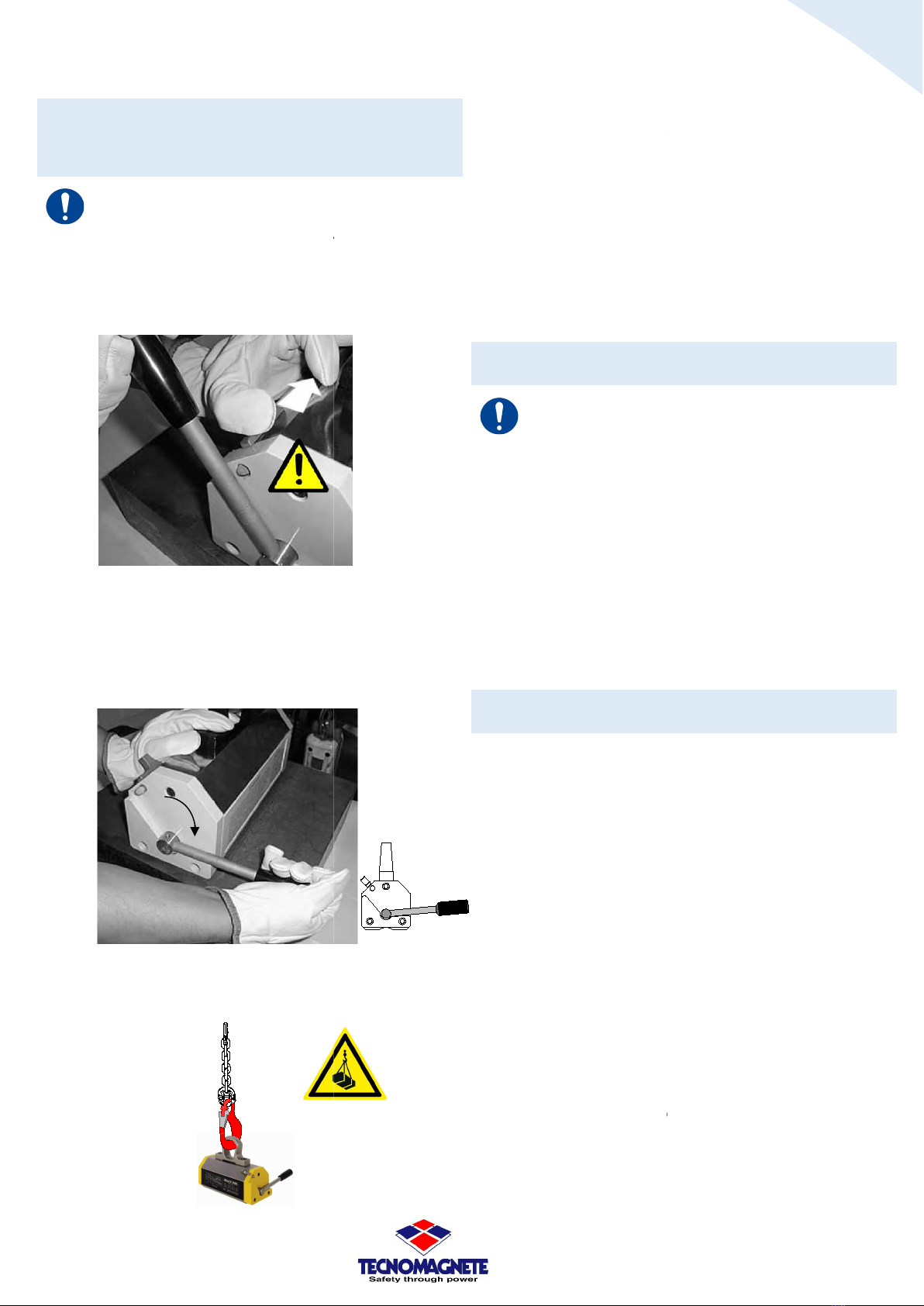
10.7 Daily Maintenace
Maintenance to be performed at the end of the daily work
activity. Depending on the method, it can be carried out by
the operator or by the handler.
For the Operational Test of the MaxX lever, it must be
placed on an iron plate resting on the ground or on a
support suitable for supporting the weights of both the
plate and the MaxX. The iron plate must have a minimum
thickness as indicated in sub-paragraph 3.2.4 (Fig.3.2.4A
and Fig.3.2.4B).
10.8 Frequent maintenance
Maintenance to be performed at the end of the work
activity within intervals of time not exceeding 3 months
(unless periods of inactivity).
The maintenance that requires a monthly frequency is
deducted from the consideration of a work activity usually
carried out on a shift of 8÷10 hours per day.
10.9 Periodical maintenance
Maintenance to be performed at the end of the work
activity within intervals of time not exceeding 12 months
(unless there are periods of inactivity).Annualmente per il
MaxX is mandatory to perform a functional and
operational test using a suitable dynamometric equipment
(this test is defined as a tear-off test).
TECNOMAGNETE is able to provide you with adequate
technical assistance to carry out the tear-off test.
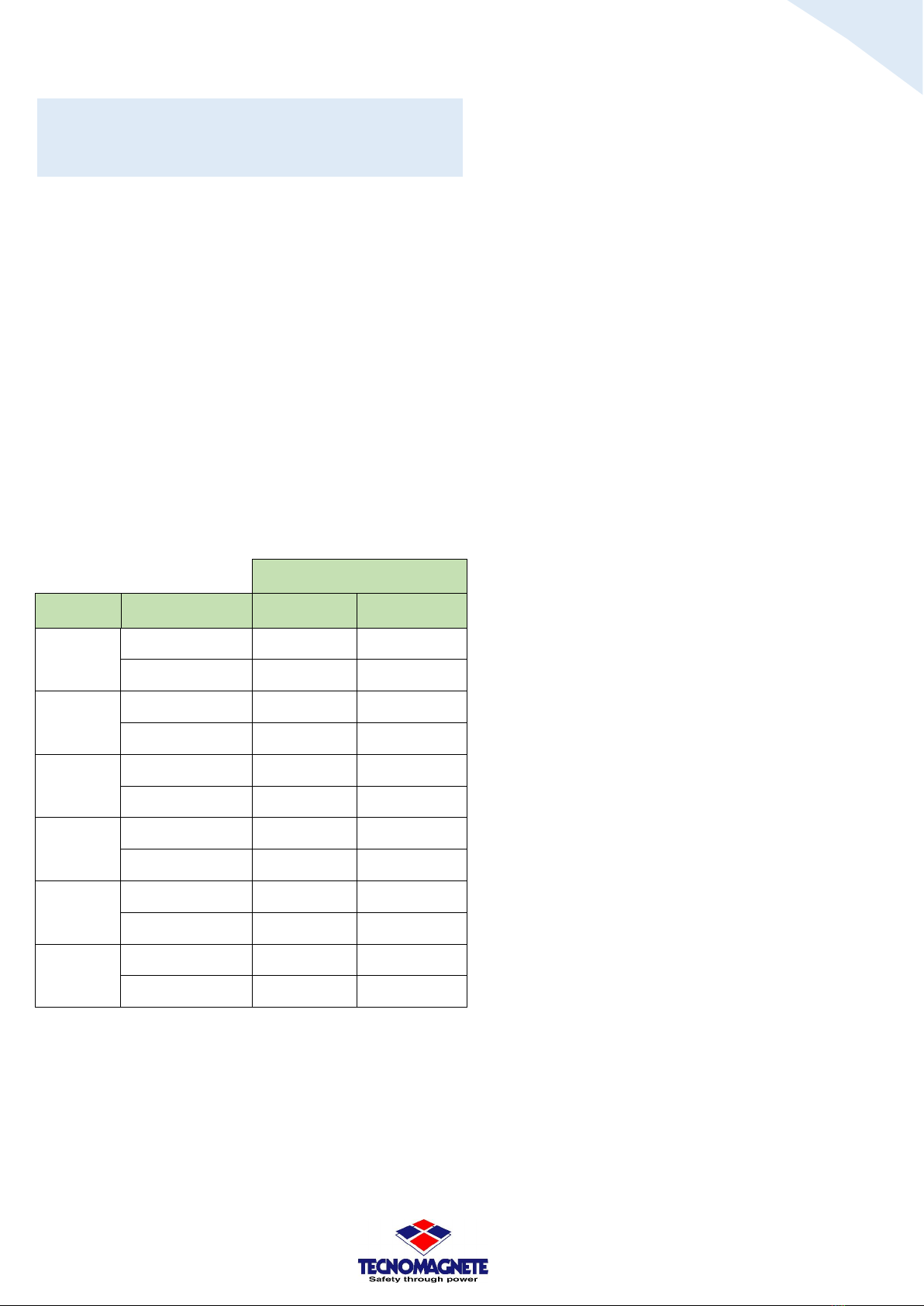
10.10 Tightening of screws
The table Fig.10.10 gives the values for the axial preload P
and the corresponding values for the tightening moments
M to be applied to the screws. The table applies to
hexagonal head screws type UNI 5737-65 and cylindrical
head screws with hexagonal socket type UNI 5931-67.
The chosen friction coefficient is 0.14 valid for machined
surfaces blackened or oiled. The tightening torque must be
applied slowly with torque wrenches.
Fig.10.10
Thread
Resistance class 8.8
Resistance class 12.9
P [N]
M [Nm]
P [N]
M [Nm]
M 6x1 9000 10,4 15200 17,5
M 8x1,25 16400 24,6 27700 41,6
M 10x1,5 26000 50,1 43900 84,6
M 12x1,75 37800 84,8 63700 143
M 14x2 51500 135 86900 228
M 16x2 70300 205 119000 346
This manual suits for next models
9
Table of contents
Other TECNOMAGNETE Lifting System manuals
Popular Lifting System manuals by other brands

MAHA
MAHA MPL 3.5 operating instructions

Lippert
Lippert HAPPIJAC owner's manual

rav
rav KPH 370.70 LIKT Translation of the original instructions

BraunAbility
BraunAbility Under-Vehicle Lift NUSP34S31X48RWO Operator's manual

Nussbaum
Nussbaum TSK 8000 Operating Manual and Inspection Book

Poweramp
Poweramp EH Series Owner & user manual

ShoreStation
ShoreStation SSV60108MS manual

Dannmar Equipment
Dannmar Equipment Max Jax Installation and operation

Stratus
Stratus SAE-UT9000 Installation, operation & maintenance instructions

Guldmann
Guldmann Cross hanger instructions

Canadian Spa
Canadian Spa CRS 20 instructions

IMER
IMER IM R13 T Use and maintenance manual