Aerovent AEHP Instruction manual

Centrifugal Fans
Installation, Operation & Maintenance Manual
Direct-Fired Gas
Air Make-Up Units
IM-875
July 2021
This manual has been prepared to guide the users of direct-fired gas air make-up units in the proper installation, operation
and maintenance procedures to ensure maximum equipment life with trouble-free operation. For safe installation, startup and
operational life of this equipment, it is important that all involved with the equipment be well-versed in proper direct-fired air
make-up unit safety practices and read this manual. It is the user’s responsibility to make sure that all requirements of good
safety practices and any applicable safety codes are strictly adhered to. Because of the wide variety of equipment covered in
this manual, the instructions given here are general in nature. Additional product and engineering information is available at
www.aerovent.com.
Refer to the Safety section(s) in this manual prior to installing or servicing the air make-up unit. The most current version of this installation
and maintenance manual can be found on our website at www.aerovent.com/resources/im-manuals.
SAFETY NOTICE
REVIEW AMCA BULLETIN 410 PRIOR TO INSTALLATION
Table of Contents
Safety & Hazard Warnings ......................................................... 2
Receiving, Inspection & Unpacking...........................................3
Unit Storage ................................................................................3
Handling ......................................................................................3
General Installation.....................................................................4
Rooftop/Curb Mounted........................................................5
Pad Mounted......................................................................... 5
Indoor/Suspended................................................................. 5
Ductwork ...............................................................................5
Unit Installation (Gas Connections)...........................................6
Piping .....................................................................................6
Sound Control .......................................................................6
Unit Installation (Electrical Connections).................................. 7
Rigging Tips & Guidelines ...........................................................8
Rigging Weights..........................................................................9
Installation Guidelines & Drawings......................................10-13
Check, Test & Start-up Procedure............................................ 14
Commissioning.......................................................................... 14
Maintenance .........................................................................14-16
Troubleshooting Guidelines ................................................. 17-19
Start-up Checklist and Report..................................................20
Field Start-Up Sheet..............................................................21-26
Maintenance Log ...................................................................... 27
Model AEHP
Model AEHV
Installation, Operation & Maintenance Manual
IM-875
2
Safety & Hazard Warnings
For general safety practices for air moving equipment, see AMCA Bulletin 410. Aerovent offers many safety accessories. These
safety devices include (but are not limited to) airflow switch, flame safety relay and high limit thermostat. The use and suitability
of safety devices is the responsibility of the purchaser.
The use and storage of gasoline or other flammable vapors and liquids in open containers in the vicinity of this appliance is
hazardous. If you smell gas:
• Open windows
• Do not touch electrical switches
• Extinguish any open flame
• Immediately call your gas supplier
Facility-related safety conditions include fans’ accessibility and location. How easily can non-service personnel access the unit? Is
the fan in a hazardous duty environment? Was the unit ordered for this duty? Other concerns must also be addressed. All fans
should be powered through switches, which are easily accessible to service personnel from the fan. Fan power must have the
ability to be “locked out” by service personnel trained in lockout/tagout procedures per OSHA requirements (29CFR1910.147).
When performing lockout, be aware of factors, such as building pressure and additional fans in the system that can influence
unwanted fan rotation (wind milling). If you have any doubt about your ability to perform a task, seek a person qualified to do that
task. Before any work is done on a fan, ensure that the fan is isolated from the electrical supply using a 'lockout/tagout system.'
Note: A stationary, non-rotating fan does not mean that the fan is isolated from the electrical supply. A non-rotating fan could be
subject to controls or other circuit protection devices that may start the fan without notice.
The following safety precautions should be followed, where applicable:
• Do not attempt to slow a rotating impeller even when it is isolated from the electrical supply. Fan impellers have a high inertia
and injury could result from an attempt to stop it. It is recommended that the impeller is isolated by closing off the inlet or
outlet to prevent wind-driven rotation. If an impeller is chocked to prevent rotation, ensure that the chocks are removed prior
to start up.
• Wear appropriate personal protective equipment. This may include protective clothing, eye protection, ear protection,
respiratory equipment, hand and foot protection when installing or servicing the fan.
• Always use caution when entering a fan's air path. High velocity airflow can cause you to lose your balance.
• Motor, bearings and drives can be hot, and similarly if the fan is subject to processes that are hot, the fan housing could be
hot.
• Fans are often used to move hazardous materials that could be dangerous. Always wear protective clothing and take
precautions not to inhale dust/gases. If hazardous chemical vapors are present, respiratory equipment may be required.
• Sharp edges – wear protective gloves when handling, installing or servicing a fan.
• Fans can operate at high decibel sound levels. Wear proper ear protection to protect from excessive noise levels.
• Access Doors – Do not open access doors when fan is in operation. The effects of suction and air pressure could result in injury.
• When working around pulleys and belts, keep hands away from pinch points. This pertains to when the fan is under or off
power.
Throughout this manual, there are a number of HAZARD WARNINGS that must be read and adhered to in order to prevent
possible personal injury and/or damage to equipment. Two signal words "WARNING" and "CAUTION" are used to indicate the
severity of a hazard and are preceded by the safety alert symbol. It is the responsibility of all personnel involved in installation,
operation and maintenance to fully understand the warning and caution procedures by which hazards are to be avoided.
DANGER: Indicates the most serious hazard and is used when serious injury or death WILL result from misuse or failure to
follow specific instructions.
WARNING: Used when serious injury or death MAY result from misuse or failure to follow specific instructions.
CAUTION: Used when minor or moderate injury or product / equipment damage MAY result from misuse or failure to follow
specific instructions.
NOTICE: Indicates information considered important, but not hazard-related.

Installation, Operation & Maintenance Manual IM-875
3
Unit Storage
If air make-up unit installation is to be delayed, store the unit in an environmentally stable and protected area. The unit should be
reasonably protected from any accidental impacts. Cover the air make-up unit to prevent any foreign material or moisture from
entering the inlet or discharge.
Receiving, Inspection & Unpacking
When the equipment is received all items should be carefully checked against the bill of lading to be sure all equipment and
loose-shipped items have been received. Before accepting delivery, carefully inspect each piece of equipment for visible shipping
damage. The unit was thoroughly inspected before leaving the factory and the carrier has accepted and signed for it. If any
damage is noticed, the carrier should make the proper notation on the delivery receipt acknowledging the damage. Make
notations of all damage on all copies of the bill of lading and have all copies countersigned by the delivering carrier. The carrier
should also fill out a Carrier Inspection Report. The factory Traffic Department should then be contacted. File claim for damage
with the carrier. Physical damage to the unit after acceptance is not the responsibility of Twin City Fan Companies, Ltd.
Unpack each air make-up unit and verify for conformance with description of product ordered and all required parts and proper
quantities of each item have been received. Refer to drawings for part descriptions. Report shortages or missing items to your
local representative to arrange for replacement parts. Due to availability of carriers and truck space, it is not possible to guarantee
that all items will be shipped together. Verification of shipments must be limited to only those items on the bill of lading.
Further inspect the unit as follows:
1. Unlatch and open unit access doors. Inspect for internal damage.
2. Remove and inspect all loose-shipped items, including remote mount control panel. Make certain all items are undamaged.
The unit nameplate must be checked to make sure the voltage agrees with the power supply available.
Handling
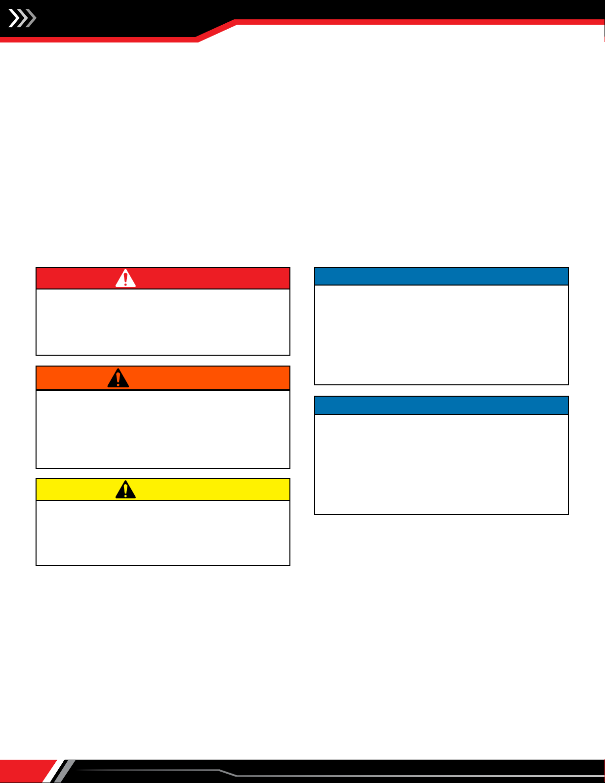
Handling of all air moving equipment should be conducted
by trained personnel and be consistent with safe handling
practices. Verify the lift capacity and operating condition
of handling equipment. When using hoisting equipment,
only qualified and trained personnel should operate the
equipment.
1. Maintain handling equipment to avoid serious personal injury and
do not stand under the load.
2. If supplied, only use the provided lifting lugs to lift the equipment.
3. Ensure that the lifting equipment is rated for the capacity to be
lifted.
CAUTION
Installation, Operation & Maintenance Manual
IM-875
4
1. Failure to comply could result in minor personal injury or
property damage.
2. Sheet metal parts, screws, clips and similar items inherently
have sharp edges and it is necessary that the installer and
service personnel exercise caution.
CAUTION
General Installation
The following recommendations are not intended to replace or void any requirements of federal, state or local codes having
jurisdiction. All local authorities having jurisdiction should be consulted before installation is made. The heater should be installed
and piped in accordance with the requirements of the National Fuel Gas Code, NFPA 54, and all wiring must be in accordance with
the National Electrical Code, NFPA 70 current edition.
If questions or complications should arise regarding the application or installation of the Aerovent Air Handling System, which
cannot be solved by using these instructions, Maintenance Guidelines or the Troubleshooting Guide, please feel free to contact
us at (763) 551-7500.
It is the responsibility of the installing contractor to see that the unit is installed within the manufacturer's design parameters, as
stated on the rating plate and that the start-up procedure specified by the manufacturer is followed. Failure to comply may void
the warranty and/or the component manufacturer's warranty.
This equipment is to be installed by an experienced installation company and fully trained personnel.
The mechanical and electrical installation of the air make-up unit consists of making final connections between the unit and
building services.
Prior to installing the unit in the final location, review the following:
1. Follow site preparation instructions for mounting recommendations.
2. Check the rating plate of the unit before lifting to ensure that the model number shown matches that shown on the plans.
Although the units may look similar, their function, capacities, options and accessories may vary widely.
3. Check the unit dimensions for proper fit.
4. Move the unit to its installation location.
5. Fully assemble the unit with all included components.
6. Inspect the blower impellers, shaft and motor for any shipping blocks that must be removed before operation.
7. Those heaters to be installed outdoors must have the Inlet Rain Hood option or other means of weather protection, whether
provided by AMU manufacturer or others.
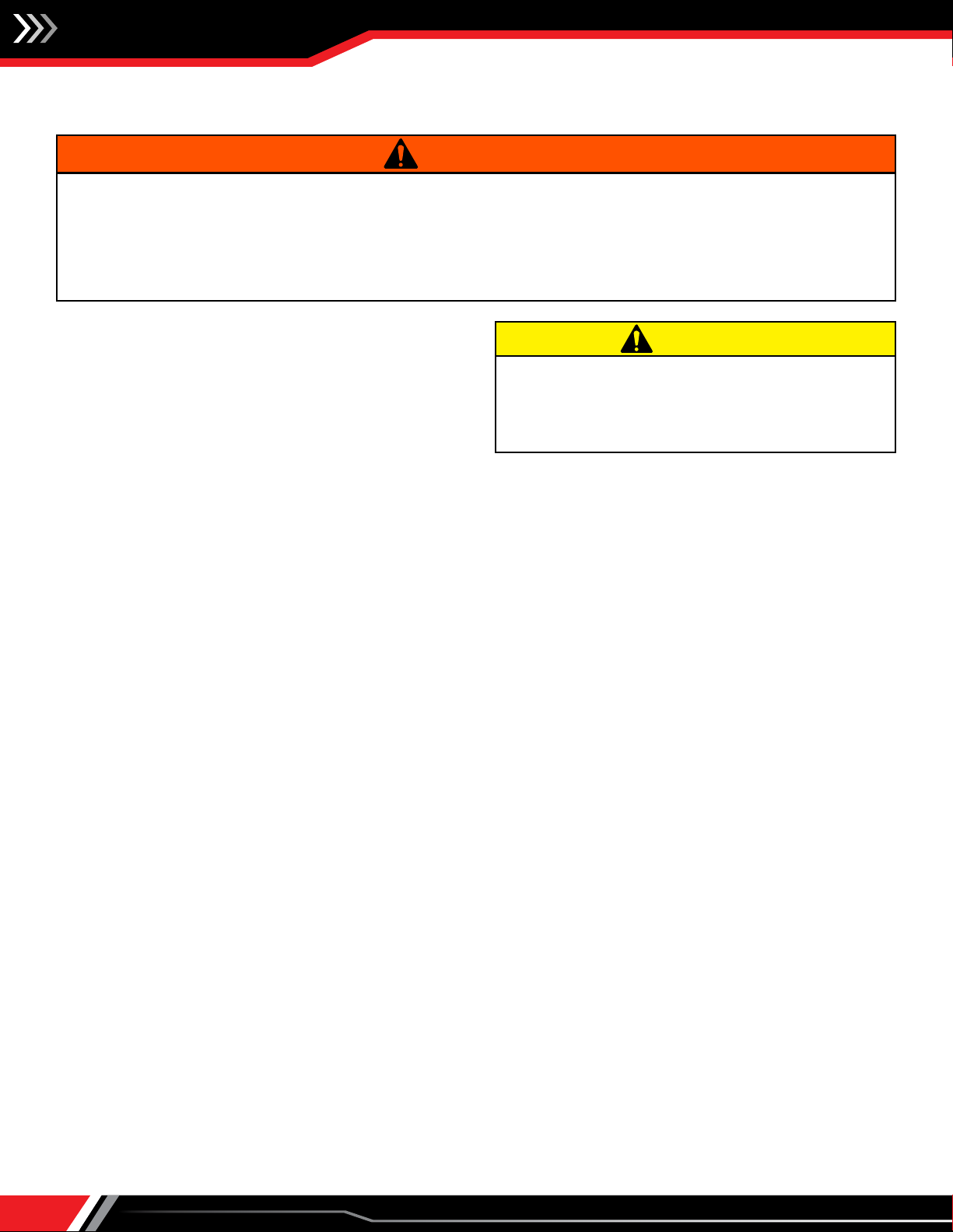
Failure to follow proper lifting and installation instructions
could result in property damage, serious injury or death.
Lifting should only be done by a qualified rigging company.
Use ALL lifting points. Test lift to ensure proper balance and
rigging. Never lift in high winds. Read the installation, operating
and maintenance instructions thoroughly before installing or
servicing this equipment.
WARNING
NOTICE
This heating unit is listed for use in Aircraft Hangers when
installed, as applicable, in accordance with ANSINFPA 409
"Standard on Aircraft Hangers:" NFPA 54 "National Fuel Gas
Code" and NFPA 90A Installation of Air Conditioning and
Ventilating System."
Before installing this equipment as a recirculating, suspended
or elevated heater for aircraft hanger use, refer to ANSI / NFPA
409 "Aircraft Hangers," Chapter 9-I for clearance and specific
installation instructions.
1. Gas-fired appliances are not designed for use in atmospheres
containing flammable vapors or dust, or atmospheres
containing chlorinated or halogenated hydrocarbons.
2. Hazard Intensity Levels: Failure to comply will result in
severe personal injury or death.
DANGER
NOTICE
This heating unit is listed for use in Parking Structures and
Repair Garages when installed, as applicable, in accordance
with NFPA 88A "Standard for Parking Structures." NFPA 54
"National Fuel Gas Code" and NFPA 90A "Installation of Air
Conditioning and Ventilating System."
Before installing this equipment as a suspended or recirculating
heater in a parking structure or repair garage, refer to NFPA
88A, Chapter 4-2 and NFPA 88B, Chapter 3-2 for clearance and
specific installation instructions.

Installation, Operation & Maintenance Manual IM-875
5
Rooftop/Curb Mounted
For a unit that discharges downward through a curb, locate the required opening for connecting ductwork. Cut through roof
deck for connection of duct to blower discharge. Allow adequate, at least one inch, clearance on all sides between ductwork and
decking material. Position the curb on the roof in relation to the roof penetration, as shown on the blueprint. Secure the curb to
the structural members. The curb may now be flashed into the roof. Rooftop, down discharge units are provided with a skirt that
is larger than the curb on all sides. This allows for roofing up to the top of the curb, if so desired.
The unit may now be lifted up onto the curb.
Note: Units that discharge down through the curb with discharge dampers must have the roof opening cut large enough to allow
access to the damper motor and linkage from below the roof. The damper should be mounted and motor wired with pigtail provided
before the unit is set on the curb.
Note: We recommend the connection of a short length of ductwork to the unit before setting on the curb to extend through the roof
if minimum (1") clearance is being used around the duct.
Pad Mounted
For a unit designed to mount on a pad or other support and discharge horizontally, vibration isolators are recommended. A
channel iron support adequate to carry the weight of the unit must be secured to the bottom of the unit, one at each end,
extending at least 3" past the sides of the unit. On AEH models, refer to your submittal or record drawing for size, quantity and
location of isolators. Anchor the vibration isolators to the pad. The unit may now be set down onto the isolators and bolted to
them.
Indoor/Suspended
For a unit designed to be suspended within the building, hanger rods and channel iron adequate to support the weight of the
unit will be required. On AEH models, refer to your submittal or record drawing for size, quantity and location of channel iron and
isolators. Attach the hanger rods to the building structure so they hang down to the channel extensions under the unit. Make
sure the rod location does not interfere with the removal of unit access panels. Provide one suspension type vibration isolator
in each hanger rod. The minimum combined ratings of the vibration isolators and suspension materials should equal the total
weight of the fully assembled unit. Move the unit to its installation location. Fully assemble the unit with all included components
(motorized discharge dampers, etc.). Raise the unit so that one hanger rod drops through holes in the channel extensions. Attach
two nuts to hanger rods and level unit, jamb the two nuts together to prevent loosening.
The unit is now ready for piping, wiring and connection to any required ductwork.
Ductwork
Ductwork must be sized and installed in accordance with applicable codes and standards. On units mounted outdoors, it is
recommended that all discharge and return air ducts be insulated to prevent condensation during the "Off" cycle in cold weather.
A fresh air intake hood with bird screen and/or filters can be supplied by Aerovent with the heater. Our intake hood or one of a
similar design is recommended.
On units mounted indoors through the roof intake ductwork, a suitable weather resistant intake hood must be installed.
Sheet metal standards should be adhered to to ensure uniform air delivery to the heater inlet. This aids in preventing moisture
entrainment. When using a through-the-wall intake duct, a properly sized intake louver should be used, having adequate moisture
baffling characteristics for the design air volume.
In lieu of an intake louver, a wall mounted intake hood with mesh screen may be used. This can be supplied by Aerovent. It is
recommended that all intake ductwork that is exposed to the heated space be insulated.
The requirements for discharge ductwork are usually considerably less than with a conventional system, as the pressurization
principle lends itself to effective air distribution. Generally, a "splash plate" or other method of distributing the air is all that is
necessary.
Installation, Operation & Maintenance Manual
IM-875
6
Piping
A male pipe connection has been provided on the outside of
the unit for connection of the gas service pipe. This is the only
gas connection required. Be sure the gas supply pipe is large
enough to ensure the proper gas volume and line pressure at
the inlet of the unit, per the unit nomenclature. Gas pipe must
be sized and installed in accordance with applicable codes and
standards. After connection of the gas pipe, check for leaks
and bleed the line.
NOTE: NFPA 54 National Fuel Gas Code requires that an approved manual gas valve be installed within six feet of the unit. We
recommend use of a gas valve with a pressure tap on the inlet to measure gas supply pressure.
NOTE: An inlet gas pressure measurement must be taken to ensure proper inlet gas pressure. Inlet pressure should be neither too
low nor too high. Check your submittal or unit nameplate for the minimum and maximum pressure requirements for your unit. If
the supply gas pressure exceeds the maximum inlet supply pressure as stated on the unit rating plate, an auxiliary high pressure
regulator must be installed in the incoming gas line by the contractor. The gas supply pressure must meet or exceed the minimum
inlet gas supply pressure, as stated on the unit rating plate, while the burner is under full fire. (See Start-Up Procedure to operate
unit on high fire.)
This heater and its gas shut-off valve must be disconnected from the gas supply piping system during any pressure testing of that
system at pressures in excess of 1/2 PSI (3.5 kPa). In addition, pressure testing of the gas supply piping system at pressures at or
below 1/2 PSI (3.5 kPa) requires isolation from the heater by closing its individual manual shut-off valve.
Sound Control
Flexible connectors should be employed on all ductwork connections. Unit vibration isolators are recommended for suspended
units and can be supplied by Aerovent as optional equipment.
DO NOT OPERATE UNIT FOR MORE THAN SIXTY (60) SECONDS WITHOUT ALL ACCESS DOORS CLOSED, WITH THE EXCEPTION
OF THE MASTER ELECTRICAL PANEL OR GAS MANIFOLD ENCLOSURE DOORS.
Energize the system and check for unusual noises or vibrations, etc. Check the fan for proper rotation. THIS MUST BE A VISUAL
CHECK as fans will move air even if they are running backwards, but the system will not perform properly. Check the amp draw
to all motors to ensure it does not exceed the maximum current rating of the motor.
If not factory installed, a low temperature limit switch should be interlocked with this heater to prevent prolonged discharge of
cold air in the event of burner lockout or shutdown.
Recirculation of room air may be hazardous in the presence of:
– Flammable liquids, solids and gases
– Explosive dusts or powders
– Substances that become toxic when exposed to heat
In order to reduce the chance of interior condensation, recirculation is not recommended in non-insulated buildings where
outdoor temperatures fall below 32°F (0°C).
Unit Installation (Gas Connections)
1. All field gas supply lines should be pressure/leak tested prior to operation. Never use an open flame. Use a soap solution or equivalent
for testing.
2. Gas pressure to the unit controls must never exceed the pressure shown on the unit rating plate. The unit and its individual shutoff valve(s)
must be disconnected from the gas supply during any test pressure more than 0.5 psig (3.5 kPa).
3. For test pressure less than 0.5 psig (3.5 kPa), the unit gas control must be isolated from the supply gas piping by closing the unit manual
shutoff valve(s).
4. For an indoor unit, where required by Code, use a dedicated line for venting gas to the outside of the building.
WARNING
1. Purging of air from gas supply lines should be performed
as described in ANSI Z223.1-latest edition “National Fuel Gas
Code” or in Canada in Can/CGA-B149 codes.
2. Do not operate unit with a gas input rate greater than that
shown on the unit rating plate.
CAUTION
Installation, Operation & Maintenance Manual IM-875
7
Unit Installation (Electrical Connections)
Wiring (Refer to unit mechanical drawing for location of electrical rough-in)
1. Installation of wiring must conform with local building codes, or in the absence of local codes, with the National Electric Code
ANSI/NFPA 70 - Latest Edition. Unit must be electrically grounded in conformance to this code. In Canada, wiring must comply
with CSA C22.1, Part 1, Electrical Code.
2. Refer to wiring diagram for numbers of wires needed for main power connection and remote control wiring. Field wiring is
shown with dashed lines.
3. Make sure all multi-voltage components (motors, transformers, etc.) are wired in accordance with the power supply voltage.
4. The power supply to the unit must be protected with a lockable fused or circuit breaker disconnect switch. If a disconnect
switch is not supplied with the unit, the field-supplied disconnect must have adequate ampacity and must be installed in
accordance with Article 430 of the National Electric Code, ANSI/NFPA 70. If not factory installed, please refer to the unit rating
plate for voltage and ampacity requirements.
5. Refer to the unit rating plate for required incoming voltage and phase. Check for concurrence with voltage and phase shown
on the wiring diagram.
6. We recommend that the wires for the control circuit be routed through the conduit provided with the main electrical service
to the equipment. This procedure is provided for in Chapter 3, Article 300-3(a) of the NFPA 70 1984 National Electrical Code. It
reads as follows: "Conductors of 600 volts or less shall be permitted to occupy the same equipment wiring enclosure, cable or
raceway, without regard to whether the individual circuits are alternating current or direct current, where all conductors are
insulated for the maximum voltage of any conductor within the enclosure, cable or raceway."
7. Open cover on disconnect box, connect line voltage wiring to terminal block provided. Then feed the control wiring through
the conduit to the master panel. Connect color coded and/or numbered control wires to terminal strip per the wiring diagram.
NOTE: Wires for Maxitrol Series 14 and Series 44 temperature controls must be run in shielded cable. For best results, run control
wiring in separate conduit if the run is over 100 feet. For longer runs, see Maxitrol Installation Instructions.
1. Electric shock hazard. Could cause severe injury or death. Failure to bond the frame of this equipment to the building electrical ground
by use of the grounding terminal provided or other acceptable means may result in electrical shock. Disconnect electric power before
servicing equipment. Service to be performed only by qualified personnel. Make sure power is turned off and locked in the OFF
position.
2. All appliances must be wired strictly in accordance with the wiring diagram furnished with the unit. Any wiring that is different from the wiring
diagram could result in a hazard to persons and property.
3. Any original factory wiring that requires replacement must be replaced with wiring material having a temperature rating of at least 221°F
(105°C).
4. Spark testing or shorting of control wires by any means will render the control transformer inoperative. DO NOT allow this to happen
as it IS NOT covered under the warranty.
WARNING
1. Ensure that the supply voltage to the appliance, as indicated on the serial
plate, is not 5% less than the rated voltage.
2. Since a failure of the unit may affect the proper operation of other fuel
burning equipment in the building, the unit shall be electrically interlocked
to open balancing air inlet dampers or other such devices.
CAUTION
Installation, Operation & Maintenance Manual
IM-875
8
Installation Technician
– Please Read Before Installing –
Rigging Tips & Guidelines
NOTES:
1. OA filter section, OA inlet hood and service platforms should be final assembled to "base unit" before lifting into place.
2. OA/RA filtered mixbox, OA louvered inlet plenum, discharge heads and roof curbs are rigged separate from the "base unit"
and assembled to the unit once in place.
3. Two-piece "base unit" models should be rigged separately and assembled in place.
4. Always use spreader bars (as shown above).
END VIEW
BASE UNIT BASE UNIT
SIDE VIEW OA FILTER
SECTION
OA/RA FILTERED
MIXBOX INLET PLENUM
OA LOUVERED

Installation, Operation & Maintenance Manual IM-875
9
Approximate Rigging Weights (lbs.)
– Please Read Before Installing –
Model
BASE UNIT OA
FILTER SECTION
OA/RA
FILTERED MIXBOX
UPRIGHT
PLENUM BASE OA INLET
HOOD
OA
FILTERED
INLET
HOOD
OA LOU-
VERED
INLET
PLENUM
UPRIGHT
SERVICE
PLAT-
FORM
SINGLE
WALL
w/20 GA.
D.W.
SINGLE
WALL
w/20 GA.
D.W.
SINGLE
WALL
w/20 GA.
D.W.
SINGLE
WALL
w/20 GA.
D.W.
P270 2,500 2,850 450 550 625 825 500 650 375 500 950 375
P330 - P365 2,750 3,200 525 650 825 1,100 700 900 450 625 1,300 375
P402 4,125 4,650 625 750 1,000 1,325 850 1,100 500 650 1,600 375
P445 - P490 4,500 5,150 750 900 1,250 1,675 1,150 1,500 625 800 2,050 500
P542 6,125 6,925 900 1,050 1,500 1,975 1,400 1,800 750 1,050 2,550 525
P600 6,550 7,425 1,000 1,175 1,750 2,300 1,600 2,050 850 1,125 3,000 550
*TWO-PIECE
UNITS Fan Burner Fan Burner
*P600 4,400 3,600 5,000 4,100 1,125 1,300 2,050 2,700 2,000 2,575 900 1,200 3,500 600
*P730 4,900 4,100 5,550 4,650 1,300 1,500 2,400 3,150 2,250 2,900 1,000 1,400 4,000 650
*P807 7,600 5,900 8,450 6,500 1,500 1,725 2,600 3,425 2,500 3,225 1,200 1,600 4,550 700
*P890 7,900 6,100 8,850 6,800 1,600 1,825 2,900 3,825 2,800 3,625 1,250 1,750 5,700 725
Model AEHP
Model
BASE UNIT
OA
FILTER
SECTION
OA/RA
FILTERED
MIXBOX
UPRIGHT
PLENUM
BASE OA INLET
HOOD
OA
FILTERED
INLET
HOOD
OA LOU-
VERED
INLET
PLENUM
UPRIGHT
SERVICE
PLAT-
FORM
w/20 GA.
D.W.
w/20 GA.
D.W.
w/20 GA.
D.W.
w/20 GA.
D.W.
V270 3,150 625 925 725 375 500 950 375
V330 - V365 3,525 725 1,225 1,000 450 625 1,300 375
V402 5,125 825 1,475 1,225 500 650 1,600 375
V445 - V490 5,675 1,000 1,850 1,650 625 800 2,050 500
V542 7,625 1,175 2,175 2,000 750 1,050 2,550 525
V600 8,175 1,300 2,550 2,275 850 1,125 3,000 550
*TWO-PIECE
UNITS Fan Burner
*V600 5,500 4,525 1,450 2,975 2,850 900 1,200 3,500 600
*V730 6,125 5,125 1,650 3,475 3,200 1,000 1,400 4,000 650
*V807 9,300 7,150 1,900 3,775 3,550 1,200 1,600 4,550 700
*V890 9,750 7,500 2,025 4,225 4,000 1,250 1,750 5,700 725
Model AEHV
Installation, Operation & Maintenance Manual
IM-875
10
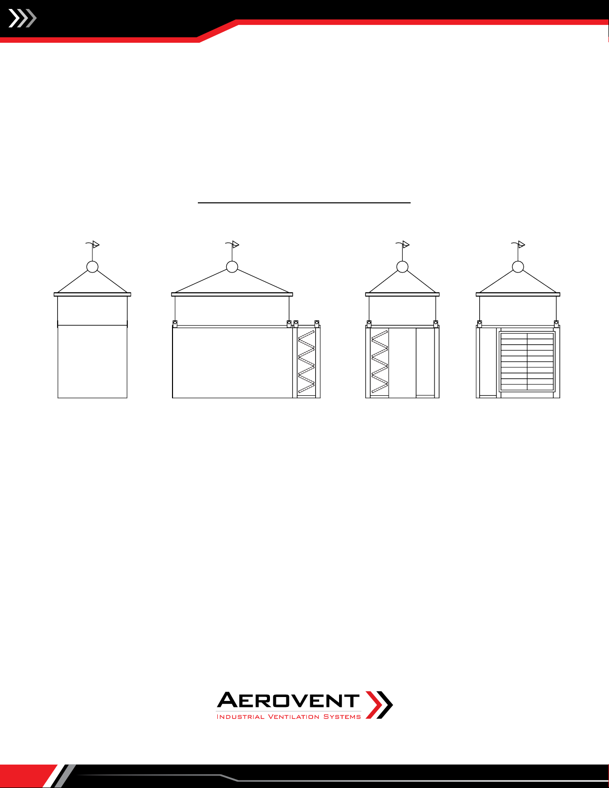
Horizontal Unit Installation Guidelines
ROOF LINE
PITCHED ROOF CURB
ROOF LINE
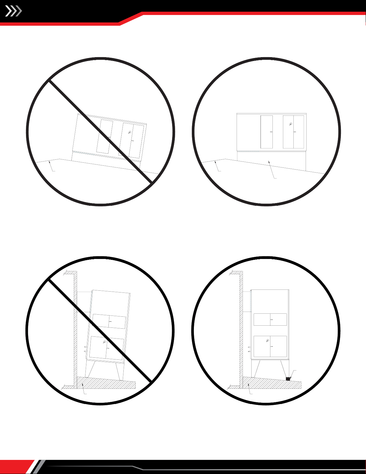
Upright Unit Installation Guidelines
MOUNTING SURFACE
MOUNTING SURFACE
SHIM PLATES
NOTE:
When installing upright equipment on warped, unlevel or raised surfaces, be sure to square/level the unit in both the X and Y axis
to ensure proper unit operation and longevity of components.

Installation, Operation & Maintenance Manual IM-875
11
Unit Leg Pad Locations
LEG PLATE DETAIL (TYPICAL)
7/8" Dia. Typ.
8
4
8
4
HEATER
33 1/2 29 1/2
59 1/2 55 1/2
73 1/2 69 1/2
87 1/2 83 1/2
105 1/2 87 1/2
124 1/2 103 1/2
3 1/4110131P807-P890
3 1/494112P660-P730
3 1/49094P542-P600
3 1/47680P402-P490
3 1/46266P270-P365
3 1/43640P182-P200
EDCB
AMODEL
7/8" Dia. Typ.
8
8
B E
C
C
A
D CC
AEHP SERIES
Installation, Operation & Maintenance Manual
IM-875
12
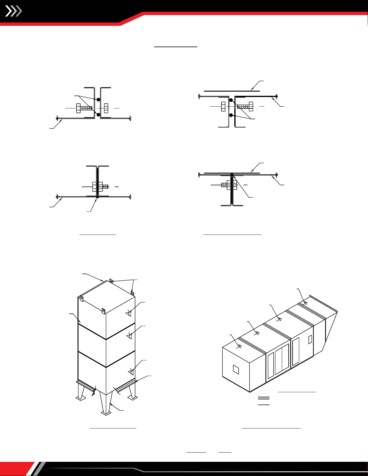
Caulking Internal Field Joints
– All field joints must be properly caulked and sealed for the heater
to operate correctly. –
NOTE:
1. All horizontal, vertical and roof joints must be heavily caulked prior to and after assembly.
HORIZONTAL MODEL
FILTERED MIXBOX
UPRIGHT MODEL
VERTICAL JOINTS
ON ALL SECTIONS
ALIGN CURB ANGLES
(TYP.)
(OUTDOOR HEATER)
SECTION
FILTERED MIXBOX
RAIN SKIRT
BURNER SECTION
LIFTING RINGS
FAN SECTION
FAN SECTION
BURNER SECTION
SECTION
HOUSING
HOUSING
ASSEMBLY
CAULK AFTER
SEALING INSTRUCTIONS
SEAL WITH A HEAVY BEAD OF CAULK
COVER WITH 3" FLASHING TAPE
INLET HOOD
INTERIOR
EXTERIOR
EXTERIOR
INTERIOR
CAULK & TAPE JOINT
ROOF SEAMS
CAULK JOINT
SIDE SEAMS
INTERIOR
EXTERIOR
EXTERIOR
INTERIOR
CAULK BEFORE
ASSEMBLY
CAULK BEFORE
ASSEMBLY
CAULK AFTER
ASSEMBLY
HOUSING
HOUSING
3
"
FLASHING TAPE
3" FLASHING TAPE - PUSH
TIGHTLY AGAINST SEAM
LEGS
FLASHING TAPE INSTALLATION INSTRUCTIONS:
1. Wipe surface clean and dry.
2. Peel backing off flashing tape.
3. Apply flashing tape firmly over field joint.
Installation, Operation & Maintenance Manual IM-875
13
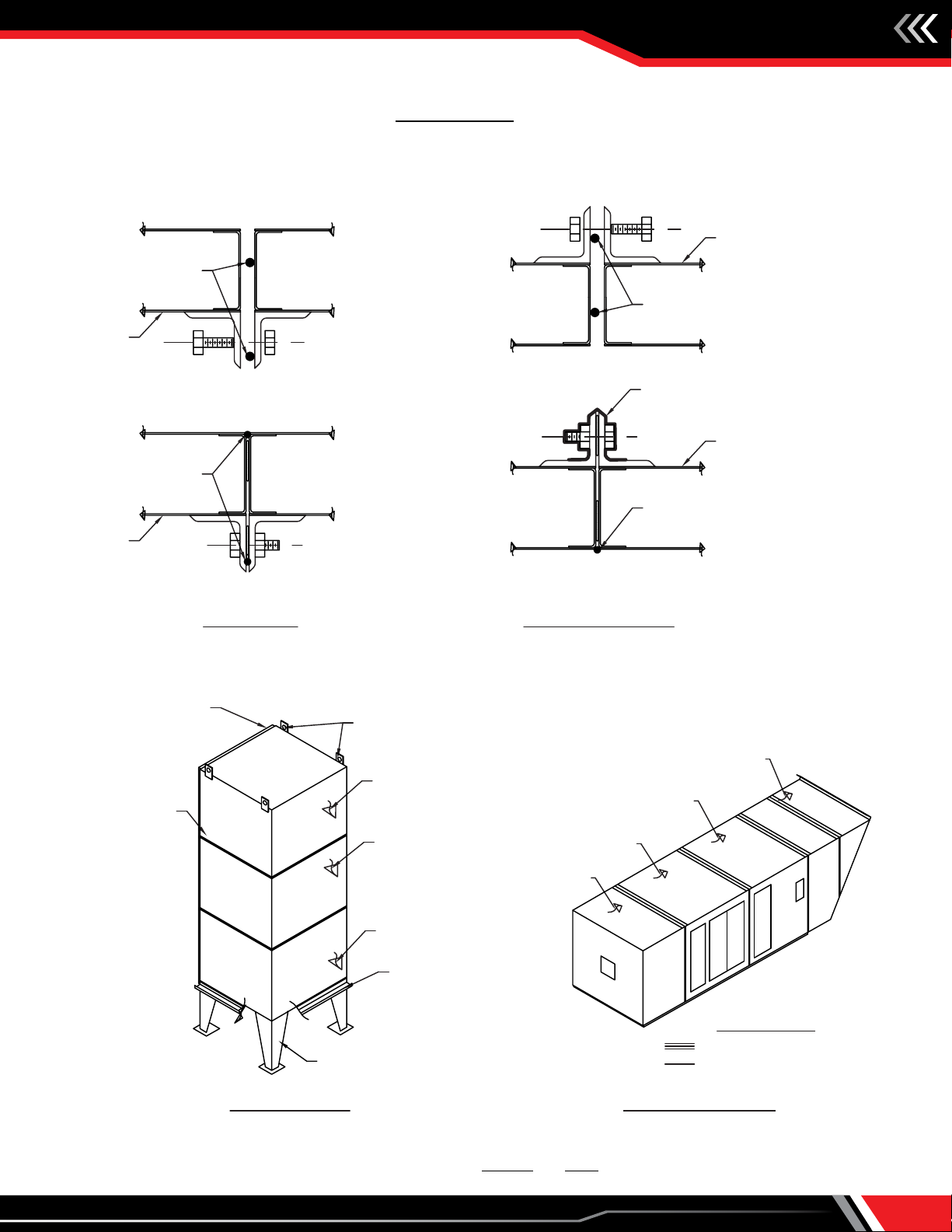
Caulking External Field Joints
– All field joints must be properly caulked and sealed for the heater
to operate correctly. –
NOTE:
1. All horizontal, vertical and roof joints must be heavily caulked prior to and after assembly.
HORIZONTAL MODEL
FILTERED MIXBOX
UPRIGHT MODEL
VERTICAL JOINTS
ON ALL SECTIONS
ALIGN CURB ANGLES
(TYP.)
(OUTDOOR HEATER)
SECTION
FILTERED MIXBOX
RAIN SKIRT
BURNER SECTION
LIFTING RINGS
FAN SECTION
FAN SECTION
BURNER SECTION
SECTION
HOUSING
SEALING INSTRUCTIONS
SEAL WITH A HEAVY BEAD OF CAULK
COVER WITH 3" FLASHING TAPE
INLET HOOD
EXTERIOR
INTERIOR
CAULK BEFORE
ASSEMBLY
INTERIOR
EXTERIOR
CAULK BEFORE
ASSEMBLY
INTERIOR
EXTERIOR
3" FLASHING TAPE - PINCH
TIGHT AROUND HARDWARE
CAULK AFTER
ASSEMBLY
CAULK AFTER
ASSEMBLY
HOUSING
CAULK & TAPE JOINT
ROOF SEAMS
CAULK JOINT
SIDE SEAMS
EXTERIOR
INTERIOR
HOUSING
HOUSING
LEGS
FLASHING TAPE INSTALLATION INSTRUCTIONS:
1. Wipe surface clean and dry.
2. Peel backing off flashing tape.
3. Apply flashing tape firmly over field joint.
Installation, Operation & Maintenance Manual
IM-875
14
Check, Test & Start-Up Procedure
Each unit is supplied with this Installation and Service Manual, which includes a Field Start-Up Form, starting on page 22. The Field
Start-Up Form must be followed and properly filled out by the installer, with one copy kept with the unit.
Before continuing with the start-up and checkout procedure, it is important to familiarize yourself with the controls and features
of the unit. Review the following:
• Documents shipped with the unit to determine which options/controls are included.
• Photographs, locations and descriptions throughout this manual for unit features, options, accessories and controls.
To properly perform the start-up, the following instruments are required:
• Ohm Meter
• Gas Pressure Gauge (range dependent on inlet pressure to unit)
• Slack Tube Manometer or 0-30" w.c. Pressure Gauge
• Inclined Manometer (0-5" w.c.)
• Handheld Tachometer (contact, reflective or strobe type)
Pre-Start-Up Inspection
Although this unit has been assembled and tested at the factory, the following pre-operational procedures must be performed
to assure the unit is ready for operation.
1. Before proceeding, turn off all power to the unit. Turn all manual hand gas valves to the closed position.
• Remove all shipping straps, braces and tie downs.
• Perform a visual inspection of the unit to make sure no damage has occurred during shipment or installation.
• Check burner and fan impeller to ensure it is secure.
• Check all electrical connections for tightness.
• Check to ensure there are no obstructions to the inlet air supply or the discharge air supply.
• Check gas piping for leaks using a soap/water solution.
2. After these preliminary checks have been made, the unit can be prepared for start-up.
1. If equipped with the factory installed disconnect switch option, when the switch is in the "OFF" position, supply power remains energized
at the supply power terminal strip and the top of the disconnect switch. When providing service on or near these terminals, building
supply power to the unit should be de-energized.
2. Proper air velocity over the burner is critical. If the velocity is not within the unit specifications, the unit will not operate efficiently, may
have nuisance shutdowns and may produce excessive carbon monoxide (CO) or other gases.
WARNING
NOTICE
Start-up and adjustment procedures should be performed by a
qualified service technician.
1. Do not operate unit with a gas input rate greater than that
shown on the unit's rating plate.
2. Purging of air from gas supply lines should be performed
as described in ANSI Z223.1-latest edition “National Fuel Gas
Code” or in Canada in Can/CGA-B149 codes.
CAUTION
Commissioning
After all the initial start-up procedures have been performed, the unit is ready for commissioning. Check the unit operation in all
modes against the job specific sequence of operation included in your unity submittals.
Installation, Operation & Maintenance Manual IM-875
15
Maintenance (refer to safety section)
All heating equipment should be serviced before each heating
season to ensure proper operation. The following items may
be required to have a more frequent service schedule based
on the environment in which the unit is installed and how
long the equipment is operated.
Motor Assembly
Check the motor sheave set screws and the motor slide base
bolts for tightness upon initial start-up and before each heating season. The motor bearings are pre-lubricated at the factory for
initial operation but should be relubricated (when provided with grease fittings) at six (6) month intervals. The recommended
lubricants are Shell Oil Company's "Dolium R", Chevron Oil's "SRI No. 2" or Texaco's "Premium RB" lubricant. When lubricating,
consider the following:
1. Clean the grease fitting and then apply the grease with a proper grease gun. Keep grease clean.
2. Use two full strokes for each bearing. Do not over lubricate.
3. Do not mix petroleum grease with silicone.
4. Lubricate motors at standstill.
Blower
After initial start-up, check the tightness of the fan sheave, fan hub set screws, fan bearing collar set screws and fan bearing
mounting bolts. Also check when retensioning the v-belts, when relubricating the fan bearings and before each heating season.
AEH Series Model Heaters: All AEH Series fan bearings should be lubricated after the first one hundred (100) hours of operation
and relubricated on a monthly basis thereafter. Aerovent recommends the use of the following (or equivalent) grease:
MOBIL SHC460 – Clean the grease fitting and then apply the grease with a proper grease gun. Inject enough grease until a small
amount shows between the seal and the bearing race. Examine the blower impeller at six (6) month intervals for accumulation
of dust and dirt on the fan blades. Any build-up must be cleaned off to maintain performance. If the accumulation is heavy, more
frequent cleaning may be required.
Belts
Due to belt stretching, adjust belt tension after the first one hundred (100) hours of operation. Check belts every three (3) months
thereafter for proper tension. Do not over tighten. Adjustment should result in a belt deflection of 3/4" to 1" for each foot of span
when applying medium thumb pressure inward at the center of the span.
Filters
Inspect monthly until an appropriate schedule can be established, based on need. Replace or clean as necessary.
Coils
Inspect and clean the coil fins on the entering air side annually. If these inspections indicate that more frequent cleaning is
required, establish a cleaning schedule accordingly. Fins should be cleaned by brushing and/or back-washing with high pressure
air or water. In extreme cases the coils may have to be removed and cleaned with high pressure steam or washed with a mild
alkali solution followed by a water rinse.
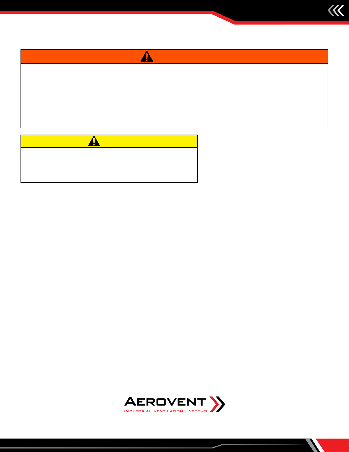
When using a drill bit to clean the burner gas ports, do not
distort or enlarge the ports. Use a pin vise not a power drill.
CAUTION
1. Electric shock hazard. Could cause severe injury or death. Failure to bond the frame of this equipment to the building electrical ground
by use of the grounding terminal provided or other acceptable means may result in electrical shock. Disconnect electric power before
servicing equipment. Service to be performed only by qualified personnel. Make sure power is turned off and locked in the OFF
position.
2. If equipped with the factory installed disconnect switch option, when the switch is in the "OFF" position, supply power remains energized
at the supply power terminal strip and the top of the disconnect switch. When providing service on or near these terminals, building
supply power to the unit should be de-energized.
3. Opening access doors on this equipment may expose user to MOVING PARTS. Your Lock-Out-Tag-Out procedures should be followed
when servicing this equipment.
WARNING
NOTICE
Service and maintenance procedures should be performed by a
qualified service agency.

Installation, Operation & Maintenance Manual
IM-875
16
Maintenance (cont.)
Traps and Strainers
Periodic inspections of traps, inspections of check and air valves, and the replacement of worn parts are important. Strainers
should be cleaned regularly.
Burners
Prior to each heating season, a check should be made of the
burner and components. Clean the igniter and flame rod and
examine porcelain for cracks. Wipe the sight glass clean on the
UV scanner and inspect the sight tube for spider webs, removing
as necessary.
Periodic maintenance will ensure continued trouble-free operation of your burner system. We recommend a yearly inspection, in
advance of the heating season.
1. Completely shut the system down, disconnecting or locking out the power supply so there can be no accidental start-up during
the inspection.
2. Inspect the burner carefully, including upstream and downstream sides of mixing plates, as well as burner body face. Any
accumulation of scale or foreign material on either side of the mixing plates should be removed with a wire brush. Check
visually that no holes in the mixing plates are blocked. If any mixing plates are loose or missing fasteners, tighten/replace as
necessary. Always use zinc-plated or stainless fasteners.
3. Check burner orifices for carbon build-up and clean if necessary. Use a pin vise with a #31 drill bit for cleaning Midco natural
gas burner orifices, a #45 drill bit for cleaning Midco propane (LPG) gas burner orifices, a #47 (5/64") drill bit for Maxon NP-I
burner orifices and a #50 (1/16") drill bit for Maxon NP-II burner orifices.
DO NOT ENLARGE BURNER ORIFICES - THIS MAY AFFECT PERFORMANCE
4. Put the system back into operation and view the burner from the downstream side while cycling the burner through its full
firing range. A good flame will be blue, with minimal yellow "fingers". The flame length in forced "high fire" should be 12-18"
long. The pilot only flame should be about the size of a baseball when properly adjusted.
Gas Train
An annual inspection of the gas control assembly should be made. Internal and external piping should be checked for leaks. Relief
vents on gas controls should be checked for clogging.
Air Pressure Switches
An annual check of the tube for the airflow switch, and the entering and leaving side of building pressure switches, should be
made to ensure against blockage.
Damper and Motor
Check linkage connection and/or set screws for tightness. Lubricate the damper bushings as required.
Painting
After unit installation, touch up any scratches caused by handling. Periodic touch-up painting should be done thereafter as
needed.
Gaskets
Inspect door gasket seals annually. Replace those showing damage or deterioration.
If this unit was not provided with an integral freeze protection
system, a low temperature limit control should be installed (if
freeze protection is needed in the event of burner shutdown).
WARNING

Installation, Operation & Maintenance Manual IM-875
17
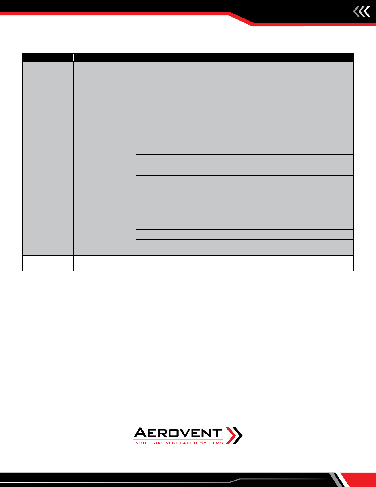
Troubleshooting Guidelines
CHECK LIGHT SYMPTOM POSSIBLE CAUSE
POWER ON POWER ON is Unlit
1. Disconnect switch is turned o (open). Turn it to ON (closed) position.
2. Fuse(s) blown on disconnect switch. Check for cause of excessive current.
Replace blown fuse(s).
3. Control fuse on transformer is blown. Check voltage on line and load side of fuse.
If there is NO voltage on load side, but there is on the line side, replace the fuse.
FAN ON
FAN ON light is Unlit
and no alarm lights
are lit.
1. Remote panel switch turned o or is defective. Check for voltage at timer coil. If
there is NO voltage, check the selector switch.
2. Damper motor auxiliary switch misadjusted or defective. Check terminals at the
damper motor. If there IS voltage and the motor is operating, but the auxiliary
switch is not closing, adjust end switch setpoint. If end switch adjustment will not
close, then replace the damper motor.
3. Voltage through end switch, but fan is not moving, check control relay 17.
Replace if necessary.
4. One (1) to three (3) of the overload heater(s) are tripped. Check for voltage at
the overload relay. If there is NO voltage, reset overloads and check motor running
amps.
5. If on INITIAL START UP of a newly installed system, the overload heaters keep
tripping, causing the fan to stop, check motor running amperage against motor
name plate full load amperage i.e. low service voltage, excessive voltage drop or
the fan is handling too much air due to less static pressure than design.
Fan does not run,
FAN ON light lit.
6. Defective contactor (Ml). Check for voltage at the contactor (coil). If there
IS voltage and the contactor does not pull in, the coil is defective. If the motor
contactor pulls in, but does not run the motor, the contacts or overload heaters
may be defective.
7. Check voltage on motor leads at starter. If voltage is present and motor does
not run, check motor wiring and connections on motor for open circuit. Check for
possible open circuit in motor windings.
HIGH TEMP High Temperature
Switch light is Unlit
1. Remote panel switch not turned to "WINTER" or "BURNER ON" position.
2. High temperature limit switch is set too low. FACTORY SET: AEH Series @ 150° F.
If there is NO voltage present at switch, adjust high limit switch.
3. Unit discharging high temperature air. Check burner gas pressure and
temperature control operation.
4. Defective high limit switch. Replace switch.
AIRFLOW
Airow switch light
is Unlit.
NOTE: All possible
causes will supply NO
voltage (120) out of
the normally open
terminal on airow
switch.
1. Fan is running backwards. Reverse any two (2) motor leads at the contactor.
(3-phase units only.)
2. Tubing to air ow switch is plugged by dirt or insects.
3. Dirt or snow obstructing the air lters.
4. Loose or worn fan belts.
5. Access door(s) open.
6. Discharge damper is frozen / binding. If frozen, this prevents the damper motor
from completing full stroke. Belimo - manual release - move manually.
7. Defective damper motor. Check terminals at the discharge damper motor. If
there IS voltage and the motor is not operating, replace the damper motor.
Make sure damper blades are moving with damper actuator.
8. Airow switch set too light. Adjust switch. 0.35" w.c. nominal @ high re.
9. Defective airow switch. Replace.
Do not reuse any mechanical or electrical component that has
been wet. Such components must be replaced.
CAUTION
NOTICE
To check most of the Possible Remedies in the troubleshooting
guide listed, refer to the applicable sections of the manual.
When servicing or repairing this equipment, use only factory-
approved service replacement parts. A complete replacement
parts list may be obtained by contacting the factory. Refer to
the rating plate on the unit for complete unit model number,
serial number and company address. Any substitution of parts
or controls not approved by the factory will be at owner's risk.
WARNING

Installation, Operation & Maintenance Manual
IM-875
18
Troubleshooting Guidelines (cont.)
CHECK LIGHT SYMPTOM POSSIBLE CAUSE
LOW GAS
PRESSURE SWITCH
Low Gas Pressure
Switch light is Unlit.
NOTE: New PSI SW
has Auto Reset of
Low Gas
1. Low gas pressure or gas supply is turned o.
2. Low gas pressure switch is set too high. Check terminals at switch. If there is
NO voltage, adjust low gas pressure switch or increase gas pressure. Investigate
pressure drop through supply piping. SWITCH IS FACTORY SET @ 3" w.c.
HIGH GAS
High Gas Pressure
Switch light is Unlit.
NOTE: This is a
manual reset switch.
1. High gas pressure at burner.
2. High gas pressure switch is set too low. If there is NO voltage at switch, adjust
high gas pressure switch or set correct burner pressure according to tag. SWITCH
IS FACTORY SET @ 5" w.c. above total gas pressure.
3. Defective high gas pressure switch.
PILOT
PILOT light remains
Unlit. If pilot lamp
turns on for a short
time then goes out,
see burner lockout
alarm light section.
1. If this unit has a mild weather switch, the outdoor air temperature maybe above
setpoint. This is FACTORY SET @ 65° F.
2. Flame relay contact screws are loose. Remove the ame relay cover and check
the contact base terminal screws for tightness.
POWER TO VALVES Power to Valves
light is Unlit.
1. If pilot light is on and power to valves is unlit, check wiring and terminals on ame
safeguard. If wiring is not damaged, replace ame safeguard.
BURNER ON Burner On light is
Unlit
1. Block valve auxiliary switch misadjusted. Check the normally open switch terminal
at the actuator. If there is NO voltage, look through the actuator observation
window. If the valve is open, adjust the actuator auxiliary N.O. switch to be closed
2. Defective actuator. Check for voltage between terminals at the coil of the
actuator. If there IS voltage, and the valve is not open, replace the actuator.
3. If there is voltage through the end switch, check CR15.
LOW TEMP On
1. Unit discharging low temperature air. Burner has dropped out due to burner
related malfunction (see burner alarm) or operation in summer mode with low
outdoor temp. 40° F or less.
2. Low temperature switch setting maybe too high. FACTORY SET @ 40° F, Time @
5 min.
3. Check sensor connections on timer. Remove sensor from timer, use OHM meter
to check continuity through sensor.
4. If low temp light lights, after the 5 min. as set on the timer, regardless of
discharge temp, check sensor. If OK, replace timer.
5. If low temp light lights, immediately in summer or winter mode, replace defective
low limit timer.
Installation, Operation & Maintenance Manual IM-875
19
Troubleshooting Guidelines (cont.)
CHECK LIGHT SYMPTOM POSSIBLE CAUSE
BURNER
LOCKOUT
Burner Lockout light
is Lit
1. If on INITIAL START UP of a newly installed system, the gas line may have air
trapped in it. Remove the test plug upstream of the safety shut o valve and bleed
the gas line to remove the air. It may require resetting the ame safeguard several
times.
2. If pilot does light as proven by the ame light on the ame safeguard, but does
not stay lit, adjust needle valve on pilot gas line. Close valve fully and open ½ turn
and retry. If pilot will not stay lit, open to 1 turn open.
3. Push burner reset button on ame safeguard or the burner reset button on
the remote panel. If burner continues to lock out, check for spark during ignition
process.
4. No ignition spark. Crack access door (or view pilot through view-port) and look at
the pilot side of the burner. You should be able to see the igniter sparking. (Spark is
present only when the pilot light is lit, this is only 10 sec.)
5. Spark plug fouled. If the spark is not visible, remove the spark plug and clean
it with a wire brush. Check the gap between ground electrode, it should be
approximately 3/32".
6. Ignition wire broken or grounded against unit.
7. Defective ignition transformer or spark plug. Disconnect the ignition wire from
the spark plug and thread it back through the hole on the control side of the unit.
Hold the wire by the insulated cover and place the spark plug electrode approx.
1/16" from a bare surface of the unit. Start the ignitions sequence; it should spark.
(REMEMBER TO RESET THE FLAME RELAY BEFORE DOING THIS.) If no spark is
observed, replace the ignition transformer.
8. Low pilot ame. Increase pilot gas pressure by adjusting pilot regulator.
9. Ultra-violet ame detector sight glass is obstructed. Check lens or sight tube for
moisture, dirt or insects. Clean or dry lens with a soft cloth.
DIRTY FILTER Dirty Filter Light
is Lit
1. If the dirty lter light is lit, the lters are dirty to the point where the airow is
reduced. Change or clean lters.

Installation, Operation & Maintenance Manual
IM-875
20
Start-up Checklist and Report
Become familiar with the equipment by looking at the fan assembly drawing for
special instructions and accessories.
NOTICE
1. This Start-Up Check List and Report must be used in conjunction with the Installation and Service Manual originally shipped with the unit,
in addition to any other accompanying component supplier literature.
2. The use of this Start-Up Check List and Report is specifically intended for a qualified installation and service agency. All installation and
service of the unit(s) to which this applies must be performed by a qualified installation and service agency.
3. After completion of start-up, make a copy of this completed form for your files as necessary and leave the original copy with the owner
for future reference.
Project Information
Project Name:
Address:
City, State, Zip:
Equipment Information
Model #:
Serial #:
Start-Up Contractor Information
Company Name:
Contact Name (print):
Contractor Address:
Telephone #:
Owner Operation and Maintenance Review
Owner/Owner's Rep Name:
Title:
CUSTOMER'S AUTHORIZED SIGNATURE:
I acknowledge that I have been instructed on the operation and maintenance of this equipment.
Signature: Date:
Telephone #:
THIS MANUAL IS THE PROPERTY OF THE OWNER. PLEASE LEAVE IT WITH THE OWNER WHEN YOU LEAVE THE JOB.
This manual suits for next models
1
Table of contents
Other Aerovent Industrial Equipment manuals


