AES Corporation IntelliPro Fire 7794A User manual

Part No. 40-7794A Rev. 3 9/20/2018
AES 7794A IntelliPro Fire
Installation Manual
AES Corporation
285 Newbury Street
Peabody, MA 01960 USA
Tel (978) 535-7310 • Fax (978) 535-7313
www.aes-corp.com
Copyright © 2017 AES Corp. All Rights Reserved

2 AES 7794A IntelliPro Fire
Part No. 40-7794A Rev. 3 9/20/2018
This page is intentionally blank.

3 AES 7794A IntelliPro Fire
Part No. 40-7794A Rev. 3 9/20/2018
Table of Contents
1. Summary................................................................................................... 6
1.1 Basic Functions ........................................................................................ 6
1.2 User Interface .......................................................................................... 6
1.3 System Knowledge Requirements........................................................... 6
Fire Alarm Control Panel Telco Interface Requirements.................... 6
1.4 Safety Considerations .............................................................................. 7
1.5 Technical Specifications........................................................................... 7
2. Installation of 7794A ................................................................................. 8
2.1 Equipment List ......................................................................................... 8
2.2 Installation ............................................................................................... 8
3. Primary Communication Interface ............................................................10
3.1 Connecting 7794A to Alarm Panel......................................................... 11
3.2 Connection Details................................................................................. 11
4. Supplemental Communication Interface ...................................................13
4.1 Connecting the 7794A to Alarm Panel (U. S. Installation).................... 13
4.2 Connection Details –7794A to Alarm Panel (U.S Installation).............. 14
4.3 Connecting the 7794A to Alarm Panel (Canadian Installation)............. 16
FACP with PSTN and RF..................................................................... 16
4.4 Connection Details –7794A to Alarm Panel (Canadian Installation) ... 17
FACP with PSTN and RF..................................................................... 17
5. Configuring the 7794A ..............................................................................19
5.1 Configuration Interface.......................................................................... 19
Reset to Defaults............................................................................... 19
6. Programming............................................................................................20
6.1 Programming Options ─ UL NOTICE TO USERS...................................... 20
6.2 Phone Line ............................................................................................. 21
6.3 Intercept Number .................................................................................. 21
6.4 Alarm Panel Report Format ................................................................... 21
CID Alarm Format.............................................................................. 22
Modem Alarm Format ...................................................................... 22

4 AES 7794A IntelliPro Fire
Part No. 40-7794A Rev. 3 9/20/2018
Pulse Alarm format ........................................................................... 23
6.5 AP Input Gain......................................................................................... 23
6.6 Intercept on Blind Dial ........................................................................... 24
6.7 Line Cut Report ...................................................................................... 24
6.8 POTS Cut Report Delay .......................................................................... 24
6.9 POTS Restoral Delay............................................................................... 25
6.10 AP Account Override.............................................................................. 25
6.11 POTS Input Gain..................................................................................... 26
6.12 Advanced Options Display ..................................................................... 26
6.13 AP Output Gain ...................................................................................... 27
6.14 Line Cut Sensing..................................................................................... 27
6.15 CID 4xx Letter......................................................................................... 27
6.16 M3 EC TEXT to CID Enabled ................................................................... 28
6.17 Voltage Pump......................................................................................... 28
6.18 Clock Frequency Shift ............................................................................ 29
6.19 Status LED Blink Patterns....................................................................... 29
7. Supported Formats/Protocols...................................................................29
7.1 Format: Contact ID................................................................................ 29
7.2 Format: Bosch/Radionics Modem II and Modem III............................. 30
7.3 Format: Pulse ........................................................................................ 31
7.4 Notes on Pulse Formats......................................................................... 32
Number of Digits on Pulse Format.................................................... 32
Double Round ................................................................................... 33
Translation of 3+1 and 4+1 to 4+2.................................................... 33
Expanded Format.............................................................................. 33
7.5 Settings for Non-Supported Formats .................................................... 33
8. Testing .....................................................................................................34
8.1 Installation Checks................................................................................. 34
9. Maintenance, Warranty and Repair ..........................................................34
9.1 Troubleshooting..................................................................................... 34
9.2 Contact Information .............................................................................. 35
10. Revision History........................................................................................35

5 AES 7794A IntelliPro Fire
Part No. 40-7794A Rev. 3 9/20/2018
12. Warranty..................................................................................................36
List of Tables
Table 1. Configuration Options for AES 7794A............................................ 20
Table 2. Blink Patterns ................................................................................. 29
Table 3. Modem Format and Speed ............................................................ 30
Table 4. Supported Bosch/Radionics Panels................................................ 31
Table 5. Supported Pulse Formats ............................................................... 32
Table 6. Recommend Fail Safe Settings ....................................................... 34
List of Figures
Figure 1. 7794A Connector and LED Locations............................................. 10
Figure 2. Primary Communications Interface Using FACP Dialers ............... 11
Figure 3. Primary and Secondary Communications Interface...................... 12
Figure 4. 7794A-to-FACP Connections ......................................................... 12
Figure 5. Connector and LED Locations........................................................ 13
Figure 6. 7794A to Alarm Panel (U.S. Installation) ....................................... 14
Figure 7. Alarm Panel Connections .............................................................. 15
Figure 8. Canada/Dual Dialer Installation..................................................... 16
Figure 9. Connecting to the Alarm Panel Using a Shared PSTN Line............ 17

6 AES 7794A IntelliPro Fire
Part No. 40-7794A Rev. 3 9/20/2018
1. Summary
This document describes the installation procedure for the AES 7794A IntelliPro Fire
module used with the AES 7707 or 7177 Subscriber in commercial Fire Alarm Control
Panel (FACP) installations.
Installed between the FACP and AES 7707 or 7177 Subscriber, the 7794A intercepts
alarm panel messages and sends them to the monitoring station via the AES 7707 or
7177 Fire Subscriber Unit.
Important! The 7794A IntelliPro and Subscriber must be connected to the FACP
within the same room and in no more than 20 feet of conduit.
1.1 Basic Functions
The 7794A is a dialer capture module with monitoring capabilities, as well as full
emulation of the POTS telephone line for incoming data sent from the FACP. The
7794A can intercept the FACP phone line connection if the intercept number matches
the number being dialed.
1.2 User Interface
The 7794A does not use configuration jumper settings and is programmed using a web
browser interface through the AES Model 7707 or 7177 Fire Subscriber. Refer to the
7707 Installation Manual, AES P/N 40-7707 or 7177 Installation Manual, AES P/N
40-7177.
1.3 System Knowledge Requirements
This document assumes that the user knows how to set the AES subscriber unit
account number, cipher, and other configuration settings as well as how to operate the
AES MultiNet software environment including IPCtrl and automation.
Fire Alarm Control Panel Telco Interface Requirements
Note: The 7794A is not compatible with Fire Alarm Control Panels that test both
digital communicator telephone lines at the same time.
With the 7794A IntelliPro used as the sole path communicator, only one telephone line
connection to the FACP is required. Parallel connect both telephone lines together, if
line 2 cannot be disabled.
Note: The 7794A can provide voltage to both telephone line connections if they are
connected together in parallel with TIP to TIP and RING to RING as shown in Figure
2 on page 11 and Figure 4 on page 12.

7 AES 7794A IntelliPro Fire
Part No. 40-7794A Rev. 3 9/20/2018
1.4 Safety Considerations
As part of the 7794A installation, the following safety considerations should be kept in
mind:
Install all equipment in accordance with the National Electric Code, National
Fire Protection Association NFPA 70, NFPA 72, and local building codes.
Test this system periodically for proper operation. AES assumes no
responsibility for this equipment's failure to operate. AES's sole responsibility
is to repair or replace any AES device found to be defective during the
warranty period.
Avoid dropping or other physical impact which could damage the card or card
components.
1.5 Technical Specifications
SIZE: 4 7/8 in. x 5 in. (12.3 cm x 12.7 cm)
WEIGHT: 0.4 pound (0.18 kilogram)
POWER INPUT: Power supplied from AES Model 7707 or 7177
VOLTAGE: 12 VDC nominal
CURRENT: 350 mA nominal; 160 mA standby
FUSE: Onboard self-resetting. Not user serviceable
OPERATING TEMPERATURE RANGE: 0° to 49°C (32° to 120°F)
STORAGE TEMPERATURE RANGE: ‒10° to 60°C (14° to 140°F)
RELATIVE HUMIDITY RANGE: 0 to 93% RH, non-condensing
Important!
The 7794A IntelliPro and Subscriber must be connected to the FACP
within the same room and in no more than 20 feet of conduit.
Notes:
The 7794A must be installed in accordance with National Electrical Codes and
UL-864.
Canadian installations must be done in accordance with Canadian Electrical
Codes, CAN/ULC-S524 and CAN/ULC-S561.
8 AES 7794A IntelliPro Fire
Part No. 40-7794A Rev. 3 9/20/2018
2. Installation of 7794A
2.1 Equipment List
The 7794A IntelliPro includes the following items:
7794A IntelliPro
AES RJ11 cable 1 each AES P/N 13-0395
Hex standoffs hardware
Hex nuts w/lock washer 4 each
Insulating washers 2 each
2.2 Installation
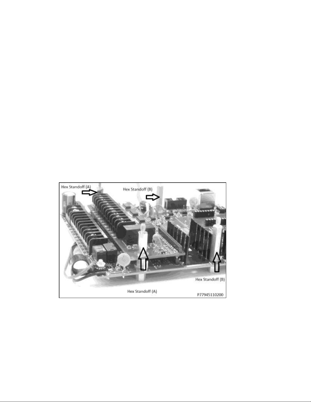
1. Place hex standoffs on mainboard in four places shown in the photo below. Use the
longer hex standoffs (B) on the mainboard, and use the shorter hex standoffs (A)
on top of the zone input card. Do not overtighten the standoffs.
2. Place the 7794A on top of the installed standoffs.
3. Install insulating washers (P/N 09-7X94) over mounting holes H1 and H3.

9 AES 7794A IntelliPro Fire
Part No. 40-7794A Rev. 3 9/20/2018
4. Place hex nuts over the washer on the standoffs to secure the board in the four
places as shown below. Do not overtighten hex nuts.
For information on connecting the fire alarm control panel PSTN wiring, refer to
either the Primary Communication Interface section on page 10 or the
Supplemental Communication Interface section on page 13, depending on your
application.
Important!
The 7794A IntelliPro and Subscriber must be connected to the FACP within
the same room and in no more than 20 feet of conduit.
10 AES 7794A IntelliPro Fire
Part No. 40-7794A Rev. 3 9/20/2018
3. Primary Communication Interface
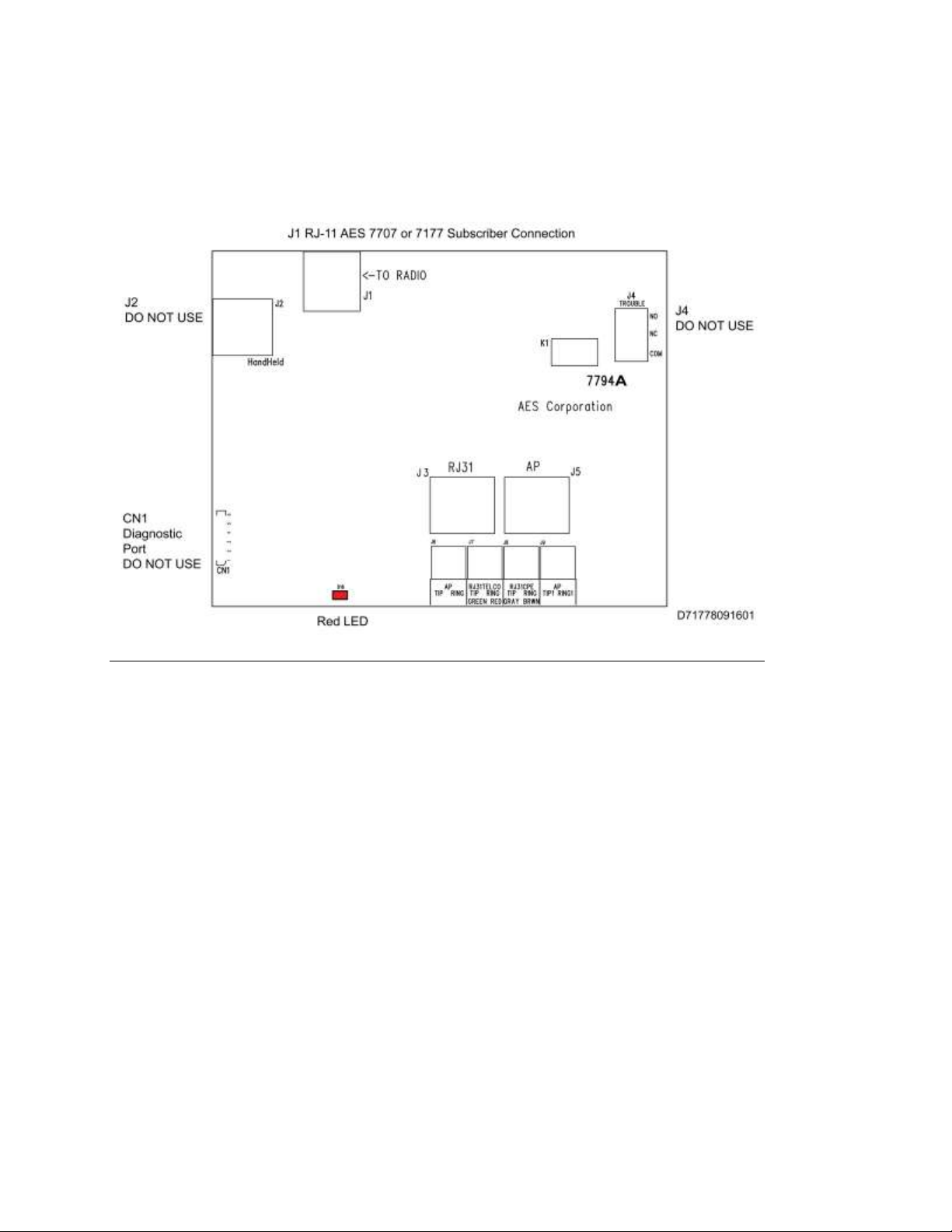
Figure 1 shows connector and diagnostic LED location on the 7794A.
Figure 1. 7794A Connector and LED Locations

11 AES 7794A IntelliPro Fire
Part No. 40-7794A Rev. 3 9/20/2018
3.1 Connecting 7794A to Alarm Panel
When mounted in a subscriber enclosure and connected to the Fire Alarm Control
Panel dialer, the 7794A delivers alarm messages to the central monitoring station as
shown in Figure 2. The 7794A is supervised by the 7707 or 7177 Subscriber, which
continuously monitors a “heartbeat” signal from the 7794A. In this configuration no
Zone inputs are connected from the FACP to the 7794A.
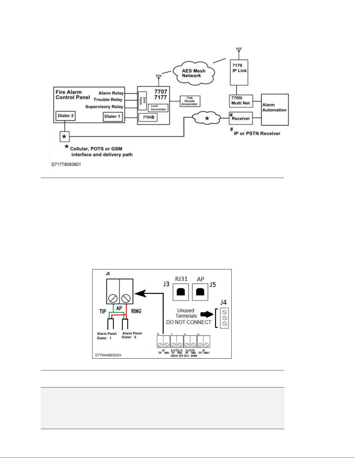
Figure 2. Primary Communications Interface Using FACP Dialers
3.2 Connection Details
When mounted in a subscriber enclosure and connected to the Fire Alarm Control
Panel dialer, the 7794A delivers alarm messages to the central monitoring station as
shown in Figure 2 and Figure 3.
Figure 3 shows a Primary Interface using a FACP Dialer and a Secondary interface
using a second FACP dialer and a Diverse Technology connection such as POTS,
GSM or TCP/IP.
Important!
The 7794A IntelliPro and Subscriber must be connected to the FACP within
the same room and in no more than 20 feet of conduit.
12 AES 7794A IntelliPro Fire
Part No. 40-7794A Rev. 3 9/20/2018
Figure 3. Primary and Secondary Communications Interface
To connect the 7794A to the FACP:
1. Extend FACP Dialer 1 and Dialer 2 TIP and RING to the 7794A.
2. Connect FACP Dialer 1 and Dialer 2 TIP wire to J6 terminal block labeled AP
TIP (see Figure 4).
3. Connect FACP Dialer 1 and Dialer 2 RING wire to the J6 terminal block
labeled AP RING (see Figure 4).
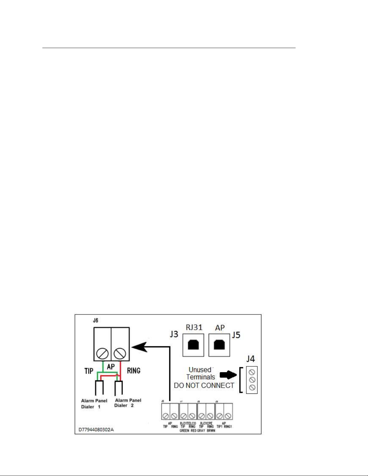
Figure 4. 7794A-to-FACP Connections
Important! Disabling Second FACP Telco Connection - most fire panels can be
configured to disable the second Telco connection, which disables panel supervision
for the second (disabled) Telco connection. Supervision alarms at the FACP can be
prevented by disabling the second Telco connection.

13 AES 7794A IntelliPro Fire
Part No. 40-7794A Rev. 3 9/20/2018
4. With the Primary Communication Interface wiring completed, proceed to the
Configuring the 7794A.
4. Supplemental Communication Interface
Figure 5 shows connector and diagnostic LED location on the 7794A.
Figure 5. Connector and LED Locations
4.1 Connecting the 7794A to Alarm Panel (U. S. Installation)
The diagram below displays the Fire Alarm Control Panel (FACP) with both dialers
connected to the 7794A (AP TIP and AP RING). Note that the output zones form the
FACP must be connected to the 7707 or 7177 in this configuration.
14 AES 7794A IntelliPro Fire
Part No. 40-7794A Rev. 3 9/20/2018
Figure 6. 7794A to Alarm Panel (U.S. Installation)
Two connection methods are used from FACP to the subscriber. The first is FACP
Dialer 1 and Dialer 2 to the 7794A. The second is FACP zone outputs to 7707 or 7177
zone inputs.
Method 1: Dialer 1/ Dialer 2 to 7794A
Method 2: FACP relays into 7707 or 7177 Subscriber Zone Inputs
Method 1 –FAILS
FACP detects Dialer 1 and Dialer 2 both in trouble
FACP trips relay "T" to 7707 or 7177
7707 or 7177 reports to MultiNet (DIALER FAILURE)
Method 2 –FAILS (antenna cut, etc.)
7707 or 7177 subscriber engages J4 Trouble Relay
J4 relay trip causes local annunciation (see 7707 Installation and Operation Manual –
AES P/N 40-7707 or 7177 Installation and Operation Manual –AES P/N 40-7177 for
details)
4.2 Connection Details –7794A to Alarm Panel (U.S Installation)
Connection from the FACP to the 7794A is provided in the instructions below:
1. Connect the FACP Dialer 1 and Dialer 2 TIP and RING to the 7794A terminal
block labeled AP TIP RING as shown in the figure below.

15 AES 7794A IntelliPro Fire
Part No. 40-7794A Rev. 3 9/20/2018
Figure 7. Alarm Panel Connections

16 AES 7794A IntelliPro Fire
Part No. 40-7794A Rev. 3 9/20/2018
2. Wire the zones of the FACP to the 7707 or 7177 as shown above in Figure 6.
Important!Disabling Second FACP Telco Connection ─ Most fire panels can be
configured to disable the second Telco connection which disables panel supervision
for the disabled connection. Supervision alarms at the FACP can be prevented by
disabling the second Telco connection.
4.3 Connecting the 7794A to Alarm Panel (Canadian Installation)
Connection from the FACP to the 7794A is provided in the instructions below.
Figure 8. Canada/Dual Dialer Installation
FACP with PSTN and RF
Method 1: PSTN via Dialer 2
Method 2: RF (7707 or 7177) via Relays
Method 3: Supplemental: RF (7794A to 7707 or 7177 ) via Dialer 1, Reverse Polarity,
Other Technologies, Relays, or other means provided by ULC S559 Listed FACP
Normal case: Alarm = Dialer 2 dials into Phone Receiver or via Dialer 1 into MultiNet
receiver
Method 1 FAILS: PSTN fails (line cut, failure to connect, etc.)
Reports with two messages:
AP detects (AP monitoring PSTN), and trip relay "T" connected to the 7707 or 7177.
7707 or 7177 subscriber sends ZONE alarm (DIALER FAILURE).

17 AES 7794A IntelliPro Fire
Part No. 40-7794A Rev. 3 9/20/2018
AP reports via Method 3. If used, 7794A-7707 or 7794A-7177 reports into MultiNet
(DIALER FAILURE).
Method 2 FAILS: antenna cut, etc.
7707 or 7177 engages J4 Trouble Relay
J4 relay trip causes local annunciation
AP reports via Dialer into Phone Receiver (RF COMMUNICATOR FAILURE)
4.4 Connection Details –7794A to Alarm Panel (Canadian Installation)
Connections from the FACP are provided in the following instructions:
1. Connect the FACP Dialer 2 TIP and RING to the PSTN (Public Switching
Telephone Network).
2. Connect the FACP Dialer 1 TIP and RING to the 7794A terminal block labeled
AP TIP RING.
3. Wire the Zones of the FACP (Alarm, Trouble, Supervision) into the 7707 or 7177
as shown above in Figure 8.
4. Connect the FACP.
Figure 9. Connecting to the Alarm Panel Using a Shared PSTN Line
FACP with PSTN and RF
Method 1: PSTN via Dialer 2
Method 2: RF (7707 or 7177) via Relays

18 AES 7794A IntelliPro Fire
Part No. 40-7794A Rev. 3 9/20/2018
Method 3: Supplemental: RF (7794A to 7707 or 7177 ) via Dialer 1, Reverse
Polarity, Other Technologies, Relays or other means provided by ULC S559
Listed FACP
Normal case: Alarm = Dialer 2 dials into Phone Receiver or via Dialer 1 into
MultiNet receiver
Method 1 FAILS: PSTN fails (line cut, failure to connect, etc.)
Reports with two messages:
AP detects (AP monitoring PSTN, and trips Trouble relay connected to the 7707 or
7177.
7707/7177 subscriber sends ZONE alarm (DIALER FAILURE).
AP reports via Method 3. If used, 7794A-7707 or 7794A-7177 reports into MultiNet
(DIALER FAILURE).
Method 2 FAILS: antenna cut, etc.
7707 or 7177 engages J4 Trouble Relay
J4 relay trip causes local annunciation
AP reports via Dialer into Phone Receiver (RF COMMUNICATOR FAILURE)

19 AES 7794A IntelliPro Fire
Part No. 40-7794A Rev. 3 9/20/2018
5. Configuring the 7794A
Configuring the 7794A IntelliPro installed in the 7707 or 7177 subscriber requires a
smartphone or another computer device with a web browser. The 7707/7177
subscriber must be configured and powered on.
5.1 Configuration Interface
The 7794A is configured through a web browser interface provided by the 7707/7177
subscriber. Refer to the 7707 Installation Manual, AES P/N 40-7707 or 7177
Installation Manual AES P/N 40-7177 for details on accessing the configuration
interface through the subscriber.
Reset to Defaults
The 7794A can be set to factory default configuration using the following steps:
1. Click on System tab:
2. Under Reset to Default, set IntelliPro Config to Yes. Click the Reset Configuration
button.
Next, the login page and the message that settings have been reset appears:
3. Login with the assigned username and password to continue with the 7794A
configuration.

20 AES 7794A IntelliPro Fire
Part No. 40-7794A Rev. 3 9/20/2018
6. Programming
6.1 Programming Options ─UL NOTICE TO USERS
NOTICE TO USERS, INSTALLERS, AUTHORITIES HAVING
JURISDICTION, AND OTHER INVOLVED PARTIES
This product incorporates field-programmable software. In order for the product to
comply with the requirements in the Standard for Control Units and Accessories for
Fire Alarm Systems, UL 864, certain programming features or options must be limited
to specific values or not used at all as indicated in Table 1. These apply when the
7794A is use as a Primary Communication Interface.
Table 1. Configuration Options for AES 7794A
Feature or
Option
Permitted
in UL (Y/N)
Possible Settings
Setting(s)
Permitted in
UL864?
Comment
Line Cut Report
Y
Y/N
Y
Select based on
use
POTS Cut
Report Delay
Y
Any value between 0-9999(seconds)
0-60 sec max.
Select based on
use
POTS Restoral
Delay
Y
Any value between 0-9999(seconds)
0-60 sec max.
Select based on
use
Line Cut
Sensing
Y
Y/N
Y
Select based on
use
M3 EC TEXT to
CID Enabled
N
Y/N
N
Table of contents
Other AES Corporation Control Unit manuals

Popular Control Unit manuals by other brands

Flowserve
Flowserve MASTER STATION IV EEP-SN4001 User instructions

VAT
VAT 590 Series Installation, operating, & maintenance instructions

ADTRAN
ADTRAN Total Access 300 Series manual

LG
LG V-Net PQDSBNGCM1 installation manual

DMP Electronics
DMP Electronics SCS-104 installation guide

Texas Instruments
Texas Instruments DP159RSB user guide


