Power
To turn the unit on press the “Power” button, the ED power
indicator will illuminate continuously.
To turn the unit off press the “Power” button, the ED power
indicator will turn off.
Internal Audible Alarm
Pressing the “Alarm” button will toggle the internal audible alarm
on and off.
When the internal audible alarm is enabled the BLUE alarm
indicator is turned off.
When the internal audible alarm is disabled the BLUE alarm
indicator is illuminated.
The status of the internal audible alarm is stored
in NVM and is retained for use after power
cycling the unit.
Note: the factory
default setting is
internal alarm
enabled.
RTE Active Waterproof Control Box
INSTALLATION AND OPERATION
ensitivity Level Tone Frequency ms of Activity
in 3 sec
1 (least sensitive) 500Hz 250
2 550Hz 200
3 600Hz 150
Connectivity
The waterproof control box has been designed for owner installation.
If, however, you do not feel confident seek the help of a professional.
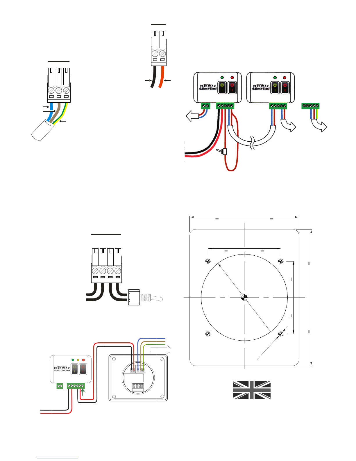
elect a position for the backing plate on a bulkhead or steering
consul and drill or cut a 57mm hole as shown on the template
supplied overleaf making sure that there are no existing wires
behind the proposed installation.
Fit cable glands to the rear section and feed the RTE, power and
extension wiring through them remembering to keep the two cable
glands at the top so they are level with the PCB connectors. If no
extension alarm is being fitted blank the single lower hole with the
blanking plug and gasket provided. For ease of attaching the wiring
as shown on page two use thin nose pliers to remove and replace
the green male terminal connectors after the wires have been firmly
attached. Only leave sufficient inner cables so that the back plate
can be fixed in position.
Gently tighten waterproof glands.
Check that the O ring is in place and press the front of the control
to the backing plate until the two pop together and are flush.
Attach the front section to the back plate using the four Allen screws
and the Allen key provided.
Audible Alarm ensitivity
The sensitivity of the audible alarm is user adjustable and
can be set to 1 of 7 different levels. The sensitivity setting
will determine the amount of ADA activity, measured in
milliseconds within a 3 second window, required to sound
the audible alarm.
To enter into the alarm sensitivity adjustment mode, press
and hold the“Alarm” button for 5 seconds until the internal
speaker emits a tone.
Subsequent presses of the “Alarm” button will increase the
sensitivity level, which is indicated by the pitch of the tone
emitted by the internal speaker, refer to Table 1.below.
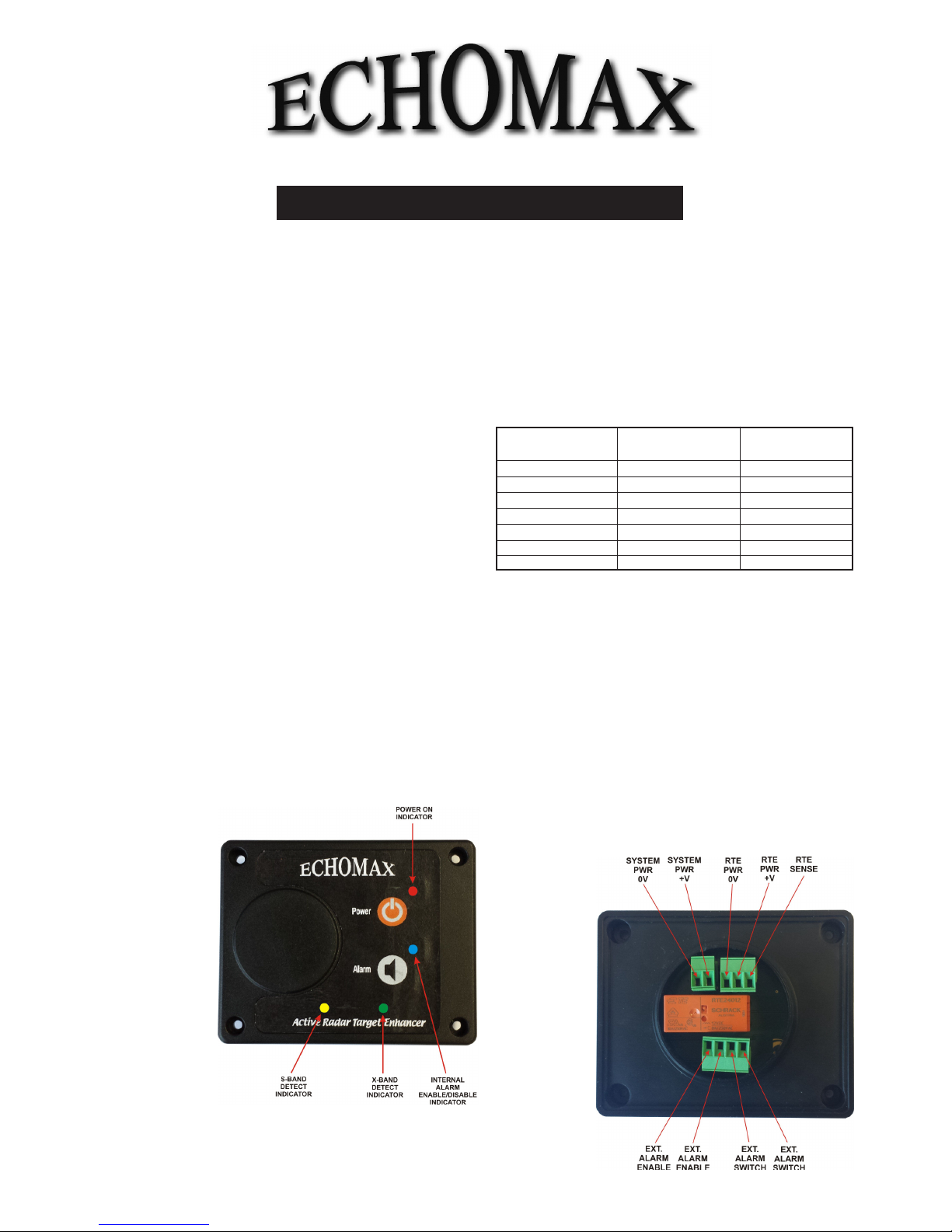
Fig. 2:
Connections at
rear of unit
Fig. 1:
Active control box
indicators
Dimensions
Length: 90mm Width: 72mm Depth: 15mm
Cut out diameter is 57mm
Overall depth 50mm (ex provision for cables)
4 650Hz 100
5 700Hz 50
6 750Hz 20
7 (most sensitive) 750Hz 20
Table 1: Alarm sensitivity chart
Once the level has reached 7 a further press of the “Alarm”
button will cause the sensitivity level to return to level 1.
Once the required sensitivity level has been reached the mode
will time out after 2 seconds of the last “Alarm” button press and
return to normal operation using the chosen sensitivity setting.
The sensitivity setting is stored in NVM and is retained for use
after power cycling the unit.
Note: the factory default setting is level 6.
Illumination
The brightness of the indicators can be adjusted for day and
night vision.
To adjust the illumination level of the indicators, press and hold
the “Alarm” button for 2 seconds; release the button
and the illumination level will change.
The illumination level is stored in NVM and is retained for
use after power cycling the unit.
Note: the factory
default setting is
day mode (the
brightest level).
& X-Band Indicators
The toggling of the internal alarm does not affect the operation
of the S-Band (YELLOW) or the X-Band (G EEN) indicators.
These indicators will illuminate each time the TE is hit with
the relevant ADA pulse.