ENC EDS800 Series User manual
SHENZHEN ENCOM ELECTRIC TECHNOLOGIES CO., LTD
Service manual
mini type
0.2-1.5KW
EDS800 series
Ver. 2.2
ISO9001:2008 Quality Management SystemAuthentication
CE Authentication

Print version:V2.2-A11
Foreword
Encom products are designed and produced according to
EN61800-5-1: 2007,EN 61010-1:2010, EN61800-3: 2004+A1:2012 standards
under ISO9001:2008 quality management system.
Thank you for purchasing EDS800 series mini universal inverter from
Shenzhen Encom Electric Technologies CO., LTD.
EDS800 series can fulfill all kinds of demand for general-purpose inverter
by advanced control manner which make high torque, high precision and
wide-range speed regulation drive be available. EDS800 is organic combine of
customer’s general need and industrial requirement to provide practical PID
adjuster, simple PLC, programmable input output terminal control, long-distance
synchronous control, impulse frequency provision and other special inverter
control with powerful function for customer and to provide highly-integrated
incorporative solution of high value for reducing system cost and improving
system reliability for device manufacturing and automatization engineering
customers.
EDS800’s big torque low noise and low electromagnetic disturbance during
operation can fulfill customer’s environmental protection requirement by space
voltage vector PWM control technique and electromagnetic
compatibility unitary design.
Assembling wiring, parameter setting, troubleshooting and daily
maintenance notice are available in this manual. To make sure that you can
correctly assemble and operate EDS800 series inverters to exert their excellent
performance, please read this user manual detailedly before you assemble the
device and conserve the manual appropriately before the end-user get them.
Please contact our office or dealer in all places at any moment if you have
any doubts or special demands when using these inverters, and you can also
contact our after service center in our headquarters directly. We will serve you
with all our heart.

We reserve our right to notice you if we change contents of this manual.
Welcome to choose other inverters of our company:
EDS-V300 series sensorless current vector control inverter
EDS1000 series multi-function universal inverter
EDS2000 series high performance universal inverter
EDS2860 series special integrative inverter for injection
molding machine
EDS3000 series high performance closed loop vector control
inverter

Contents
1 Safety information and use notice points
1.1 safety precautions
1.2 use range
1.3 use notice points
1.4 scrap notice points
2 Type and specification of the inverter
2.1 incominginverterinspect
2.2 typeexplanation
2.3 nameplateexplanation
2.4 seriestypeexplanation
2.5 appearance and parts name explanation
2.6 outersizeandgrossweight
2.7 outer size of keypad and its fixing box
2.8 product technic index and spec
3 Installation and wiring
3.1 installationambient
3.1.1 demandforinstallationambient
3.1.2 installationdirectionandspace
3.2 partsdisassemblyandinstallation
3.2.1 key board disassembly and installation
3.2.2 plasticcoverdisassembly
3.3 wiringnoticepoints
3.4 main loop terminal wiring
3.4.1 connection between inverter and fitting parts
3.4.2 mainloopterminalwiring
3.5 basicrunningwiringdiagram
3.6 controlloopcollocationandwiring
3.6.1 location&function of terminal and jump-wire
3.6.2 explanation for control panel terminal
3.6.3 analog input output terminal wiring
3.6.4 communicationterminalwiring
1
1
2
2
4
5
5
5
5
6
6
19
6
7
7
10
10
10
10
10
11
11
12
12
14
14
13
14
16
10
18

3.7 installationguideforanti-jamming
3.7.1 restraining to noise disturbance
3.7.2 localewiringandearthing
3.7.3 relation of long-distance wiring and current leak
and the countermeasure
3.7.4 installation demand for electromagnetic on-off
electronic device
4 Run and operation explanation for inverter
4.1 runofinverter
4.1.1 runningorderchannels
4.1.2 frequency-provision channel
4.1.3 workstate
4.1.4 runmode
4.2 operation and use of key board
4.2.1 keypadlayout
4.2.2 keypadfunctiondescription
4.2.3 LEDandindicatorlight
4.2.4 keyboarddisplaystatus
4.2.5 method for operating keypad
4.3 inverterelectrification
4.3.1 checkbeforeelectrification
4.3.2 first electrification
5 Functionparameterschedulegraph
5.1 symboldescription
5.2 function parameter schedule graph
6 Detailedfunctiondescription
6.1 basic run function parameter group: F0
6.2 start-up, stop, braking function parameter group:F1
6.3 auxiliary run function parameter group:F2
6.4 closed-loop run control parameter: F3
6.5 simple PLC run function parameter group:F4
6.6 terminal correlative function parameter group: F5
20
20
22
23
23
24
24
24
24
24
25
26
26
26
28
30
33
33
33
27
67
35
35
35
58
76
81
51
51
56

6.7 traverse special function
p
arametergroup:F6
6.8 frequency provision function parameter group: F7
6.9 motor and vector control function parameter group: F8
6.10 protection function parameter:F9
6.11 failurerecordfunctionparameter:Fd
6.12 code and manufacturer function parameter: FF
7 Troubleshooting
7.1 failureandcountermeasure
7.2 failurerecordlookup
7.3 failure reset
8 Maintenance
8.1 routinemaintenance
8.2 inspection and replacement of damageable parts
8.3 repairguarantee
8.4 storage
9 Examples
9.1 common speed regulation running
9.2 terminalcontrolrunning
9.3 multi-step speed control running
9.4 closed-loopcontrolsystem
9.5 consecutiveactionrunning
10 Modbus communication protocol
Appendix 1 Serial port 485 communication protocol
Appendix 2 Braking resistance
109
93
95
110
111
112
112
114
115
116
123
111
134
97
98
101
102
108
108
109
103
103
106
106

EDS800 series Service Manual
1
1 Safety information and use notice points
In order to ensure the safety of your personal and equipment, before using the
inverter, please read this chapter of contents conscientiously.
1.1 Safety precautions
There are three kinds of safe relevant warnings in this service manual, they
are as follows:
This symbol explains items that need to be paid attention to when being
operated.
This symbol is briefed on some useful information.
This symbol briefs on: If does not operate on request, may cause death,
severely injured or serious property loss.
.
(1) Forbid to connect U, V, W output end to AC power supply, otherwise cause the
complete damage of the inverter.
(2) Don't make P- and P + short-circuited, otherwise cause the inverter to be
damaged.
(3) The inverter is forbidden to install on the flammables, otherwise have danger of
fire.
(4) Don't install it in the environment with explosive gas, otherwise have danger of
causing explosion.
(5)After connecting main loop, should carry on insulating treatment to bare wiring
end, otherwise have danger of getting an electric shock.
(6) If being connected to the power supply, don't operate the inverter with moist
hands, otherwise have danger of getting an electric shock.
(7) The ground terminal of the inverter must be grounded well.
(8) Inverter being connected to power supply, please don't open cover and carry on
wiring, can connect the wire or check only after closing power for 10 minutes.
(9) Only qualified personnel may carry on wiring and forbid leaving over any
conductive thing in machine, otherwise have danger of getting an electric shock
or causing damage of the inverter.
(10) Inverter stored for over 2 years, should be stepped up gradually with voltage
regulator first while having the electricity, otherwise have danger of getting
electric shock and explosion.
!
!
note
!

EDS800 series Service Manual
2
1.2 Use range
(1) This inverter is only suitable for three phases AC asynchronous motor in general
industrial field.
(2) While applying inverter to such equipments that relate much to the life, great
property, safety devices etc., must handle cautiously, and consult with producer,
please.
(3) This inverter belongs to the control device of general industrial motor, if used in
dangerous equipment, must consider the security safeguard procedures when the
inverter breaks down.
1.3 Use notice points
(1) EDS800 series inverter is voltage-type inverter, so temperature, noise and
vibration slightly increasing compared to power source running when using,
belongs to normal phenomenon.
(2) If need to run for a long time with constant torque of low-speed, must select
motor of frequency conversion for use. Use general asynchronous AC motor
when running at a low speed, should control temperature of the motor or carry
on heat dissipation measure forcedly, so as not to burn the generator.
(3) Such mechanical device needing lubricating as the gearbox and gear wheel, etc.,
after running at a low speed for a long time, may be damaged as lubrication
result become poor, please take necessary measure in advance.
(4) When the motor running with frequency above specified, besides considering the
vibration, noise increase of the motor, must also confirm speed range of the
motor bearing and the mechanical device.
(5) For hoist and great inertia load, etc., the inverter would shut off frequently due to
over-current or over-voltage failure, in order to guarantee normal work, should
consider choosing proper brake package.
(1) It is prohibited that connect AC220V signal to control ends except TA, TB, TC,
otherwise have danger of damaging property.
(2) If the inverter is damaged or without all parts, please don't install and operate it,
otherwise have danger of fire or cause personnel to be injured.
(3) When installing, should choose a place where can endure the inverter, otherwise
have danger of injuring personnel or damaging property while falling down.
!
EDS800 series Service Manual
3
(6) Should switch on/off the inverter through terminal or other normal order
channels. It is prohibited that switch on/off the inverter frequently by using
strong electric switch such as magnetic control conductor, otherwise will cause
the equipment to be damaged.
(7) If need to install such switch as the magnetic control conductor, etc. between
inverter output and the motor, please guarantee the inverter is switched on/off
without output, otherwise may damage the inverter.
(8) The inverter may meet with mechanical resonance of the load within certain
range of frequency output, can set up jumping frequency to evade.
(9) Before using, should confirm the voltage of the power is within the working
voltage range allowed, otherwise should vary voltage or order special inverter.
(10) In the condition of altitude above 1000 meters, should use the inverter in lower
volume, reduce output current by 10% of specified current after each 1500
meters height increasing.
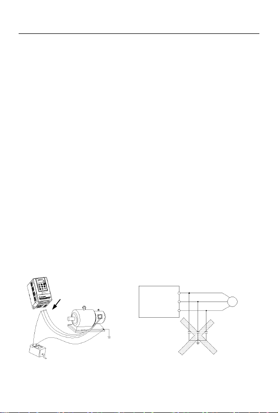
(11) Should make insulation check to the motor before using it for the first time or
after a long time placement. Please inspect with 500V voltage-type megohm
meter according to method shown as graph1-1 and insulation resistance should
not be smaller than 5 MΩ, otherwise inverter may be damaged.
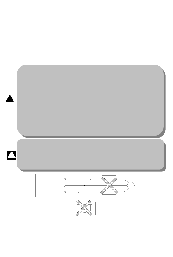
(12) To forbid assembling capacitor for improving power factor or lightningproof
voltage-sensible resistance etc., otherwise will cause malfunction trip of the
inverter or damage of the parts, shown as graph 1-2.
Fig.1-1 motor insulation measure Fig.1-2 capacitor at output side forbidden
U
V
W
M
EDS800
EDS800
motor
Grounding part
Megohm meter
U VW
After wiring, short-circuit U, V, W
to measure insulation resistance.

EDS800 series Service Manual
4
1.4 Scrap notice points
When disposing scrap inverter and its parts, please note:
(1) The unit: please discard as industrial useless.
(2) Electrolytic capacitor: when burning the inverter electrolytic capacitor in it
may explode.
(3) Plastic: when plastic, rubber parts etc. in the inverter are burning, they may
bring bad, poisonous gas, so please be ready to safeguards.
EDS800 series Service Manual
5
2 Type and specification of the inverter
2.1 Incoming inverter inspect
(1) Check if there is damage during transportation and inverter itself has damage or fall-off
parts.
(2) Check if parts presented in packing list are all ready.
(3) Please confirm rated data of the inverter is in line with your order requirement.
Our product is guaranteed by strict quality system during manufacturing,
packing, transportation etc., please contact our company or local agent rapidly if
some careless omission or mistake arise, we’ll deal with it as soon as possible.
2.2 Type explanation
EDS800– 4 T 0015 B
Fig. 2-1 type description
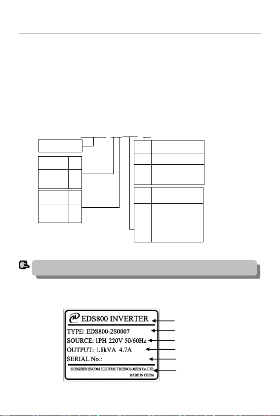
2.3 Nameplate explanation
Nameplate presented as figure 2-2 with type and rating data at the bottom of
inverter right side.
If the inverter hasn’t relevant content or can be defaulted, code after “/” will be ignored.
note
Fig.2-2 Nameplate
Type
Serial No.
Rated input volt. and frequency
Output apparent power
Series No.
Manufacturer
code Fitting part
Bbuilt-in brake unit
Cbuilt-in brake unit
&brake resistance
code Motor power
(KW)
0002
0004
0007
0015
0.2
0.4
0.75
1.5
Input volt. Code
Single phase
3 phase
S
T
Volt. grade code
220V
380V
2
4
Inverter serial no

EDS800 series Service Manual
6
2.4 Series type explanation
Table 2-1 series type explanation
Inverter type
Rated power
(KVA)Rated output
current(A)Adapted motor
(KW)
EDS800-2S0002 0.6 1.6 0.2
EDS800-2S0004 1.1 3 0.4
EDS800-2S0007 1.8 4.7 0.75
EDS800-2S0015 2.8 7.5 1.5
EDS800-4T0007 1.5 2.3 0.75
EDS800-4T0015 2.4 3.7 1.5
2.5 Appearance and parts name explanation
Fig. 2-3 Parts name sketch for EDS800
2.6 Outer size and gross weight
Fig.2-4 Outline Image
analog potentiometer
power input and inverter output terminal
take this part off to connect
brake resistance(options)
terminal cover
LED
control cable inlet
top cover
keypad
vent
EDS800 series Service Manual
7
Table 2-2 EDS800-2S0002~EDS800-4T0015 mounting size
Inverter type W
(mm)
H
(mm)
D
(mm)
D1
(mm)
A
(mm)
B
(mm)
Fixing
aperture
(mm)
Gross
weight
(kg)
EDS800-2S0002
85 141.5 112.5 126 74 136 5
1
EDS800-2S0004 1
EDS800-2S0007 1.1
EDS800-2S0015 1.2
EDS800-4T0007 1.1
EDS800-4T0015 1.1
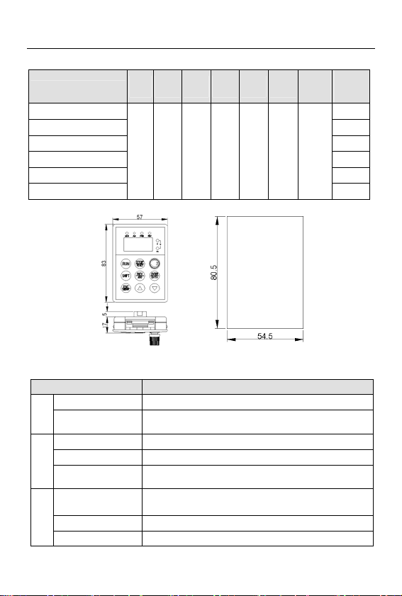
2.7 Outer size of keypad and its fixing box (unit: mm)
Fig.2-5 outer size of keypad and outline of its fixing box
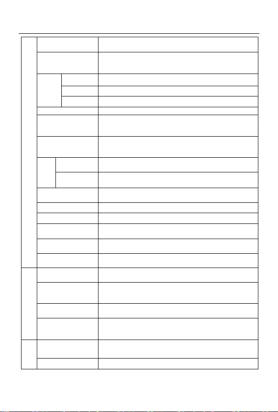
2.8 Product technic index and spec.
item Item description
Input
Rating volt.,frequency 3 phase 380V, 50Hz/60Hz; single phase 220V, 50Hz/60Hz
Allowed work volt. range 3 phase voltage: 320V~460V;
single phase voltage: 200V~260V
output
Voltage 380V grade: 0~380V; 220V grade: 0~220V
Frequency 0Hz-400Hz
Over loading capacity 150% of rating current for1 minute,200% of rating current for 0.5 second;
Control
performance
Control mode Optimum space voltage vector SVPWM constant volt. Frequency ratio V/F
control
Speed regulation range 1:100
Start-up torque 100% of rating torque at low frequency
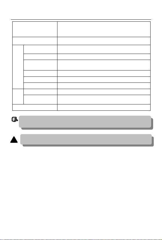
EDS800 series Service Manual
8
Running speed stable state
precision ≤±0.5% of rating synchronous speed
Frequency precision Digital setting: max. frequency×±0.01%; analog setting:
max.frequency×±0.5%
Frequency
resolution
Analog setting 0.1% of max. frequency-+96
Digital setting 0.01Hz
Exterior pulse 0.5% of max. frequency
Torque boost Automatic torque boost,manual torque boost 0.1%~20.0%
V/F curve (volt. frequency
characteristic)
Set rating frequency randomly at range of 5~400Hz,can choose constant
torque, degressive torque 1, degressive torque 2, degressive torque 3 in total
4 kinds of curve
Accelerating decelerating
curve
2 modes: straight line accelerating decelerating and S curve accelerating
decelerating; 7 kinds of accelerating decelerating time (unit
minute/second can be optioned), max. time 6000 minutes.
brake
Powerconsumption
b
rake exterior brake resistance
DC brake Optional start-up and stop,action frequency 0~15Hz,action volt. 0~15%,
action time 0~20.0 s
Jog Jog frequency range: 0.50Hz~50.00Hz; jog accelerating decelerating time
0.1~60.0s can be set
Multisection speed running Realized by interior PLC or control terminal
Interior PID controller Be convenient to make closed-loop system
Automatic energy save
running Optimize V/F curve automatically based on the load to realize power save
running
Automatic volt. regulation
(AVR) Can keep constant output volt. When power source voltage varies.
Automatic current limiting Limit running current automatically to avoid frequent over-current which
will cause trip
Running function
Running order specified
channel Key pad specified, control terminal specified, serial port specified
Running frequency
specified channel Digital provision, analog provision, impulse provision, serial port provision,
combined provision,can be switched at any time by kinds of method
pulse output channel Impulse square wave signal output of 0~20KHz,can realize output of
physical parameter such as setting frequency, output frequency etc.
Analog output channel 1 channel of analog signal output,AO channel can be 4~20mA or 0~10V;
through it the inverter can realize output of physical parameter such as
setting frequency, output frequency etc.
keypad
LED display Can display setting frequency, output frequency, output voltage, output
current etc. in total 14 kinds of parameter
Lock the button Lock all or part of the buttons(analog potentiometer can’t be locked)
EDS800 series Service Manual
9
Protection function Over-current protection, over-voltage protection, lack-voltage
protection, over-heat protection, over-load protection, missing phase
protection (in option)etc.
Fitting parts brake subassembly, remote-control keypad, connecting cable for
remote-control keypad etc.
ambient
Use ambient indoor,not bare to sunlight,no dust, no corrosive gas, no flammable
gas, no oil fog, no vapor, no water drop or salt etc.
altitude Lower than 1000m
Ambient temperature -10ºC~+40ºC(under ambient temperature 40ºC ~50ºC, please reduce the
volume or strengthen heat sink)
Ambient humidity Smaller than 95%RH, no condensation water
vibration Smaller than 5.9m/s²(0.6g)
Storage temperature -40ºC~+70ºC
Config-
uration
Defending grade IP20
Cooling mode By fan with automatic temperature control
Mounting mode Wall hanging
To exert excellent performance of this inverter, please choose correct type and check
relevant content according to this chapter before wiring for use.
note
Must choose correct type, otherwise may cause abnormal running of the motor or
damage
!

EDS800 series Service Manual
10
3 Installation and wiring
3.1 Installation ambient
3.1.1 Demand for installation ambient
(1) Installed in drafty indoor place,ambient temperature within -10ºC~40ºC,need
external compulsory heat sink or reduce the volume if temperature exceeds40ºC.
(2) Avoid installing in place with direct sunlight, much dust, floating fibre and metal
powder.
(3) Forbid to install in place with corrosive, explosible gas.
(4) Humidity should be smaller than 95%RH,without condensation water.
(5) Installed in place of plane fixing vibration smaller than 5.9m/s²(0.6g).
(6) Keep away from electromagnetic disturbance source and other electronic
apparatus sensible to electromagnetic disturbance.
3.1.2 Installation direction and space
(1) Normally the inverter should be mounted vertically, horizontal mounting will
seriously affect heat dissipation and the inverter must be used in lower volume.
(2) Demand for minimum mounting space and distance,please see Fig.3-1.
(3) When install multiple inverters up and down, must apply leading divider between
them, see fig. 3-2.
Fig. 3-1 mounting space Fig. 3-2 mounting of multiple inverters
3.2 Parts disassembly and installation
3.2.1 Key board disassembly and installation
(1) disassembly
Let the forefinger press finger inlet on the keypad,depress fixing flexible plate on
the top lightly, draw it outward, then you can disassemble the keypad.
(2) assembly
in
ve
rt
e
rinverter
Leading
divider
50mm
mm or more
100 mm or more
100mm or more
50mm
mm or more
Fan
exhaust
EDS800 series Service Manual
11
First place the fixing hook at the bottom of keypad onto mounting claw on
keypad mounting hole, let forefinger press fixing flexible plate on top of keypad
and then push it inside, release it in proper location(after a crisp sound).
3.2.2 Plastic cover disassembly
Put the finger into handle hole on the bottom of cover, lift it, then you can
disassemble the cover.
3.3 wiring notice points
Fig.3-3 banned magnetic control conductor and absorbing capacitance between
inverter and motor
U
Inverter V
W
M
(1)Before wiring, assure power supply is cut off completely for 10 minutes and all LED indicator ligh
extinguished.
(2)Before internal wiring, confirm that DC volt. Between main loop end P+ and P- fall down to below DC36V.
(3)Wiring can only be done by professional person trained and qualified.
(4)Before electrification, check if voltage grade of the inverter is in line with that of power supply volt.,
otherwise will cause personnel injured and device damaged.
!
(1)Assure power cuf off completely for above 10 minutes before wiring, otherwise have danger of
getting electric shock.
(2)Forbid connecting power wire to output U, V, W of the inverter.
(3)There is current leakage in the inverter and leak current of middle/high power inverter is bigger than 5mA,
for safety reason,inverter and motor must be earthed safely, commonly use 3.5mm² above copper wire as
ground wire and ground resistance smaller than 10Ω.
(4)Before shipment compression resistance test of the inverter is passed,so user should not conduct
compression resistance test again.
(5)Should not assemble electromagnetic contactor and absorbing capacitance or other absorbing device,
see Fig.3-3.
(6)To be convenient to over current protect of input side and power off maintenance inverter should be
connected to power supply through relay.
(7)Connecting wire for relay input and output loop(X1~X8, OC1~OC4, FWD, REV), should use above
0.75mm² glued wire or shielding wire,one shielding layer end hung in the air, the other connected to
grounding end PE or E, connecting wire shorter than 20m.
!

EDS800 series Service Manual
12
3.4 Main loop terminal wiring
Fig.3-4 main loop simple wiring
3.4.1 Connection between inverter and fitting parts
(1) Must assemble disjunction device such as isolation switch etc. between
powersource and the inverter to assure personal safety when repairing the inverter
and needing compulsory power off.
(2) Power supply loop must have breaker or
fuse with over current protection function to
avoid malfunction expanding caused by failure
of after device.
(3) AC input reactor
If high-order harmonics between inverter and
Power supply is biggish which can’t fulfil
system requirement, or need to improve input
side power factor, AC input reactor is needed.
(4) Magnetic control conductor only be applied
to power supply control and don’t apply
magnetic control conductor to controlling on/off
of the inverter.
(5) Input side EMI filter
Can use EMI filter to inhibit high-frequency
conduction disturbance and emission
disturbance from inverter power supply wire.
(6) Output side EMI filter
Can use EMI filter to inhibit emission disturbance
noise and wire leakage current from output side.
(7) AC output reactor
Advise assembling AC outputreactor to avoid
motor insulation damage, too large over current
and inverter frequent protection when connecting wire from inverter to motor
Power
supply
L1
L2
L3
U
W
PE
V M
EDS800
3 phase breaker
AC ouput reactor(in option)
Output EMI filter (in option)
Braking resistor
Brake unit
Input EMI filter(in option)
Magnetic control conductor
AC input reactor(in option)
Breaker or fuse
Isolation switch
EDS800
PE W
V
U
L1 L2 L3
L1
L2
L3
N
(in option)
M
Fig.3-5 connection of inverter and fitting parts
EDS800 series Service Manual
13
exceeds 50m.But voltage drop of AC output reactor must be considered. Improve
input output voltage of the inverter or let the motor in lower volume to avoid
burning off the motor.
(8) Complete ground wire
Inverter and motor must be earthed and grounding resistor smaller than
10Ω.Grounding wire should be shorter enough and wire diameter be bigger
enough(not smaller than 3.5mm²):
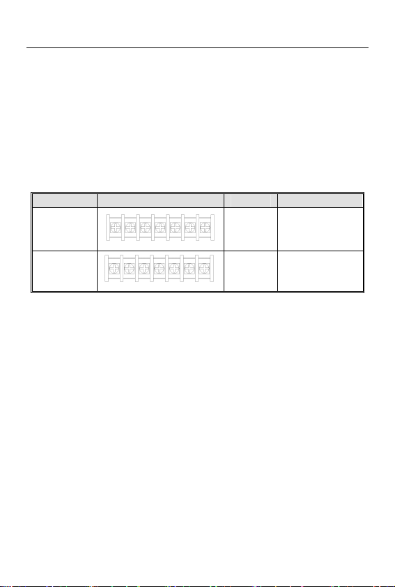
3.4.2 Main loop terminal wiring
For main loop input output terminal, see table 3-1.
Table 3-1 main loop input output terminal description
Adapted type Main loop terminal End name Function description
EDS800-2S0002~
EDS800-2S0015
L1
L2
E
U,V,W
Zero wire
live wire
Grounding terminal
3 phase AC output end
EDS800-4T0007
EDS800-4T0015
L1,L2,L3
E
U,V,W
3 phase AC intput end
Grounding terminal
3 phase AC output end
L1 L2 UV
W
E
L1 L2 UVW
E
L3
EDS800 series Service Manual
14
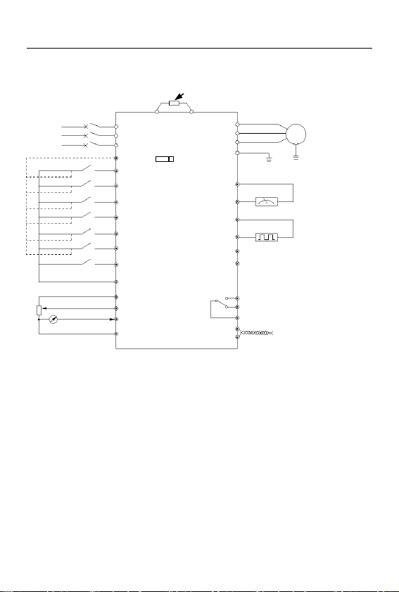
3.5 Basic running wiring diagram
Notice1:When FWD,RWV,X1~X5 terminal imput signal need low level(or pup
joint with COM) is effective. Please put JP3 on “L”.
Notice2:When FWD,REV,X1~X4 terminal imput signal need high level(or pup
joint with +10v) is effective. Please put JP3 on “H”.
3.6 Control loop collocation and wiring
3.6.1 Location&function of terminal and jump-wire:
For location of terminal and switch on the CPU board, please see Fig.3-7.
Function description of terminal provided for the user, please see Table 3-2,
function and setup description of switch, please see Table 3-3,terminal CN1 is for
manufacturer’s use. Should carry on terminal wiring correctly and set switch on the
CPU board before using the inverter,to use at least No.24 conducting wire as
terminal connecting wire is recommended.
Fig. 3-6 basic wiring diagram
Braking unit (external,fitting part, interface at the
right side of inverter )
P+ PB
L1
L2
L3
breaker
forward run/stop
reverse run/stop
multi-function 1
multi-function 2
m
ulti-function 3
m
ulti-function 4
multi-function 5
FWD
REV
X5
X4
X3
X2
X1
U
V
W
E
GND
AO
DO
OC
TA
TB
TC
485A
485B
EDS800
Standard RS485
communication port
Malfunction relay output
open circuit collector output
Cymometer
Output 12V impulse signal
M
0~10V or 4~20mA
0~10V
speed command
+10V
VCI
CCI
GND
COM
power
su
pp
l
y
DC amperometer
4-20mA current signal
or 0~10v voltage signal
COM
OCG Maximum 220VAC, 0.5A
+10V JP3
H L
multi-function5 canbe
used for high spee
d
pulse input
①Notice 1
②
N
otice2
This manual suits for next models
6
Table of contents
Other ENC Inverter manuals


