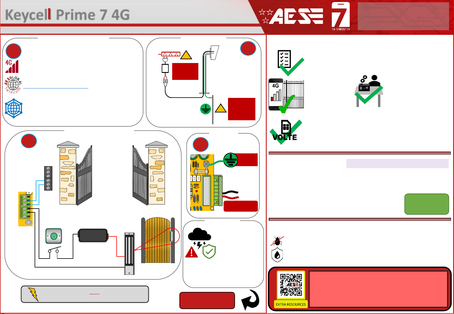
AES Keycell Prime 7 4G User manual

Ensure there is good
4G signal on site. 4G
units will fall back to
3G service in some
countries.
SITE SURVEY
This product requires a regular voice & SMS SIM card.
Do not use a data only SIM, as this will not work in the unit.
TIP: Most technical calls received are due to installers using CAT5 or alarm cable
to power the unit.
NEITHER are rated to carry enough power! ( 1.2amp peak )
Please use the following cable:
Up to 2 metres ( 6 feet ) –Use minimum 0.5mm2( 18 gauge )
Up to 4 metres ( 12 feet ) –Use minimum 0.75mm2 ( 16 gauge )
Up to 8 metres ( 24 feet ) –Use minimum 1.0mm2( 14 gauge )
POWER CABLE KEEP POWER SUPPLY AS CLOSE AS POSSIBLE.
Power
Consumption:
80mA
INGRESS PROTECTION
We recommend sealing all entry holes for prevention of insects that can
cause issues with a risk of shorting out components.
To maintain the IP55 rating please follow the sealing instructions included.
(also available online)
Set up on a bench in workshop
BEFORE going to site.
Program the unit in the comfort
of your work bench and call
technical support should you
have any questions.
Please read this entire manual before installing this
product. A full comprehensive manual is available on
our website for additional information.
Keycell Prime 7 4G - Advanced GSM Keypad/Prox Reader
STILL HAVING TROUBLE?
Find all of our support options such as Web Chat,
Full Manuals, Customer Helpline and more on
our website:
WWW.AESGLOBALONLINE.COM
* ALWAYS TEST THE UNIT ON SITE BEFORE INSTALLATION TO AVOID RE-STOCKING FEE * See full T&C’s on our website
LIGHTNING PRONE AREAS MUST USE SURGE PROTECTION
FOR POWER SUPPLY!
Relay Connections
4
See overleaf for
more PCB details
SIM Preparation
Ensure you read all instructions before continuing.
The SIM cards provided need activated before
use. Follow the instructions provided or visit our
telecoms website for more details:
www.aesglobaltelecom.com
1
1
Site Wiring
Power
3
2
!
!
14 gauge - 24 ft MAX Earth rod
close as
possible to
device!
Use 110V
surge
protection!
To Earth
Rod!
Earthing
This product MUST
be EARTHED in
the following states
in order to qualify
for manufacturers
warranty
FL, LA, MS, AR, OK, MO, AL, IL,
KY, TN, IN, KS, SC, GA, IA, TX,
OH, NC, NE, MD, WV, VA, DE
24V DC IN
(PSU included)
Relay1
Relay 2
COM
N/C
N/O
COM
N/C
PRESS
TO EXIT
Optional
Exit Button Separate
lock PSU
Driveway
Gates
Gate
Controller
N/C
N/O
Magnetic Lock
NEED MORE ASSISTANCE?
+1 (321) 900 4599
SCAN THIS QR CODE TO BE BROUGHT TO OUR RESOURCES PAGE.
VIDEOS | HOW-TO GUIDES | MANUALS | QUICK START GUIDES
Different networks use different APNs,
and these must be set correctly for full
operation. See Details overleaf on
setting a new APN.

DETECT
Gate Position
Limit switch
(optional)
OPEN
Exit Button
(optional)
1 2 3 4
ON DIP
SLAVEIN
SLAVEOUT
1 2 3
1 2 3
IN
+ 24V -
OUT
+ 24V -
IN
1 2 3
OUT
1 2 3
COIL
Master Wiring Connections Note: Amaximum of 6 auxiliary units
can be connected to 1 master unit.
Relay 2
ALTERNATIVE WIRING EXAMPLE ALTERNATIVE WIRING EXAMPLE
Relay STRIKE
LOCK
Relay
SECONDARY
MAGNETIC LOCK
LOCK POWER
SUPPLIES
ARE NOT
INCLUDED AS
PART OF THE
KIT.
These diagrams are provided for
guidance only. Please refer to the lock
wiring instructions before connecting.
2
Keypad
SLAVE CONNECTIONS
PWR |COMMs
SLAVE
CONNECTIONS
POWER
------------
COMMs
Tip: Keypad and
Prox combination
is an optional
extra.
Relay 1
Keycell Prime 7 4G - Advanced GSM Keypad/Prox Reader
STILL HAVING TROUBLE?
Find all of our support options such as Web Chat,
Full Manuals, Customer Helpline and more on
our website:
WWW.AESGLOBALONLINE.COM
* ALWAYS TEST THE UNIT ON SITE BEFORE INSTALLATION TO AVOID RE-STOCKING FEE * See full T&C’s on our website
Master Unit Keypad or
Prox
RVT
RVT
RVT
RVT
RVT
RVT
RVT
RVT
101101
Relay 1
Relay 2
8.000
USB
PCB Status LEDs
SOLID RED = PCB POWERED ON
SOLID RED +BLUE FLASHING = SEARCHING
SOLID RED + BLUE FLASHING + GREEN FLASHING
= SUCCESSFULLY CONNECTED
SIM ORIENTATION
ALWAYS ensure the system is switched
OFF when adding or removing your
SIM card and ensure the orientation is
correct.
CONNECTION TO NETWORK
4G: Quick Flashing =Standby | Constant ON/OFF = Searching
MODEM LED
INDICATOR
CHANGE APN (for VoLTE / 4G services)
Check with your network provider for the correct APN for 4G data.
Once you have confirmed the APN enter it in place of ‘APNinfo’ in an SMS to the intercom.
via SMS
(if connected to network)
9999#97APNinfo#
Passcode APN info
for SIM
network
Command
(add APN)
1. Power off the unit, then press and hold the call
button and power the unit on again.
2. Upon power up, a long tone will be emitted from
the speaker and the blue LED will remain solid - it is
now in the APN setting mode.
3. After this, enter the APN serial number through
the keypad then press #.
(e.g. if you want to set APN No. 18, press 1 - 8, then #.
A long beep will again be heard).
4. Reboot unit.
via Keypad (if no 3G signal)
Contact Technical Support or check our resource page
for a list of the APN serial number.
24v DC IN PB Terminals
Ensure the PCB is powered on and connected
to the network with a GREEN flashing LED.
Then send the below text as an SMS to the
intercom Sim number. A power reboot is
required after the ‘OK’ reply message is
received back.
SIM
The system will arrive with an AES SIM and will be pre-programmed with the APN to suit. If you
wish to use a different SIM then the correct APN must be set for full operation.

Master Unit Keypad or Prox
RVT
RVT
RVT
RVT
RVT
RVT
RVT
RVT
101101
Relay 1
Relay 2
8.000
USB
1 2 3 4
1 2 3
1 2 3
COIL
RVT
RVT
RVT
RVT
RVT
RVT
RVT
RVT
101101
Relay1
Relay2
8.000
USB
IN
+ 24V -
Master +
Auxiliary
1 2 3 4
1 2 3
1 2 3
COIL
RVT
RVT
RVT
RVT
RVT
RVT
RVT
RVT
101101
Relay1
Relay2
8.000
USB
IN
+ 24V -
Master
Only
Auxiliary Wiring Connections (Optional)
Keycell Prime 4G - Advanced GSM Keypad/Prox Reader
STILL HAVING TROUBLE?
Find all of our support options such as Web Chat,
Full Manuals, Customer Helpline and more on
our website:
WWW.AESGLOBALONLINE.COM
* ALWAYS TEST THE UNIT ON SITE BEFORE INSTALLATION TO AVOID RE-STOCKING FEE * See full T&C’s on our website
All connections will be pre-wired to the ‘Sounder PCB’
so you just need to connect each unit together
Detailed wiring diagrams available online.
Auxiliary Units are optional extras.
Up to 6 separate units can be added to a single master.
This will provide a maximum of 8 separate relays to control.
3
Auxiliary Prox
1 2 3 4
ON DIP
24V 1 2 3 NC COM NO PTE
24V 1 2 3
1 2 3 4
ON DIP
SLAVEIN
SLAVEOUT
1 2 3
1 2 3
IN
+ 24V -
OUT
+ 24V -
IN
1 2 3
OUT
1 2 3
COIL
Auxiliary Prox and Keypad
12-24v
IN
SLAVE IN
1 2 3
12-24v
OUT
SLAVE OUT
1 2 3
1 2 3 4
ON DIP
24V 1 2 3 NC COM NO PTE
24V 1 2 3
1 2 3 4
ON DIP
SLAVEIN
SLAVEOUT
1 2 3
1 2 3
IN
+ 24V -
OUT
+ 24V -
IN
1 2 3
OUT
1 2 3
COIL
Auxiliary Keypad
1 2 3 4
ON DIP
24V 1 2 3 NC COM NO PTE
24V 1 2 3
12-24v
IN
SLAVE IN
1 2 3
12-24v
OUT
SLAVE OUT
1 2 3
If the master is the only unit being used keep the ‘jumper’ on for
the use of both relays on the board.
The jumper link needs to be off for the programming and use of
auxiliaries.
1 2 3 4
ON DIP
24V 1 2 3 NC CO M NO PTE
24V 1 2 3
OPEN
Exit Button
(optional)
Auxiliary Unit
1 2 3 4
ON DIP
24V 1 2 3 NC COM N O PTE
24V 1 2 3
OPEN
Exit Button
(optional)
Auxiliary Unit
12-24v
IN
SLAVE IN
1 2 3
12-24v
OUT
SLAVE OUT
1 2 3
Master Unit
Remove the 4 x nylon screws and lift
off the main assembly to access the
auxiliary out connections if required
Keypad Only
Keypad & Prox or
Prox Only
1 2 3 4
ON DIP
SLAVEIN
SLAVE OUT
1 2 3
1 2 3
IN
+ 24V -
OUT
+ 24V -
IN
1 2 3
OUT
1 2 3
COIL
12-24v
IN
SLAVE IN
1 2 3
12-24v
OUT
SLAVE OUT
1 2 3
Two cores for
power and
three for
communication
Maximum Distance
CAT 5 cable –50m per power supply with a max of 2 power supplies
Jumper Link
(Found on Prox and Keypad Boards)
Send SMS 9999#001# to enable auxiliary unit(s)
Unit(s)

4
1 2 3 4
ON DIP
24V 1 2 3 NC COM NO PTE
24V 1 2 3
1 2 3 4
ON DI P
SLAVE IN
SLAVE OUT
1 2 3
1 2 3
IN
+ 24V -
OUT
+ 24V -
IN
1 2 3
OUT
1 2 3
COIL
45 6
1 2 3
7 8 9
*0 #
The sounder boards dip
switches set the relay number
for the auxiliary unit it is in.
A keypad does not have dip switches. To assign
the relay number use the keypad keys as follows.
Keypad
The dip switch of the prox
must match the dip switch
configuration of the
auxiliary it wants to trigger
Auxiliary Device
Relay Setup
Relay 3 Relay 4 Relay 5
Relay 6 Relay 7 Relay 8
ON DIP
1 2 3 4
ON DIP
1 2 3 4
ON DIP
1 2 3 4
ON DIP
1 2 3 4
ON DIP
1 2 3 4
ON DIP
1 2 3 4
*#91#RelayNumber#
(Relay Number = 3-8)
Sounder Board Prox Board
4
Keycell Prime 7 4G - Advanced GSM Keypad/Prox Reader
STILL HAVING TROUBLE?
Find all of our support options such as Web Chat,
Full Manuals, Customer Helpline and more on
our website:
WWW.AESGLOBALONLINE.COM
* ALWAYS TEST THE UNIT ON SITE BEFORE INSTALLATION TO AVOID RE-STOCKING FEE * See full T&C’s on our website

Download the App and
Accept all permissions when
the app is opened
1
Choose
your
language
2
5
Additional App Configuration/Help
Device Setup
Getting Started
Register
your details
3Sign in using
previously
registered email
and password
4
Enter the
information
required to set
up the device
(This process
can take up to
7 screens)
Add additional
app users
Choose your
device from the
list provided
Customise
Advanced
Features
(more on this
on pg4)
If you are having
trouble the help
section has
troubleshooting
and How to
Videos to help
you resolve the
problem
Keycell Prime 4G - Advanced GSM Keypad/Prox Reader
STILL HAVING TROUBLE?
Find all of our support options such as Web Chat,
Full Manuals, Customer Helpline and more on
our website:
WWW.AESGLOBALONLINE.COM
* ALWAYS TEST THE UNIT ON SITE BEFORE INSTALLATION TO AVOID RE-STOCKING FEE * See full T&C’s on our website

SIM MAINTENANCE
If using a pre-pay casual SIM card it will need topped up occasionally. It is recommended to advise the
home owner / end user to register the SIM card on the provider’s web site if available. Most major
networks allow registration of card payment details for an auto top up feature, which means they will
automatically top up your intercom when the balance runs low or in some cases, they offer a low balance
reminder to be sent if they do not wish the auto top up feature.
ENVIRONMENTAL INFORMATION
WARRANTY
6
UNIT MAINTENANCE
Bug ingress is a common issue in unit failures. Ensure that all components are sealed accordingly and check
occasionally. (Do not open the panel in the rain / snow unless correctly equipped to keep the internals dry.
Ensure the unit is securely closed after maintenance)
The equipment that you bought has required the extraction and use of natural resources for its
production. It may contain hazardous substances for the environment. In order to avoid the
dissemination of those substances in our environment and to diminish the pressure on the natural
resources, we encourage you to use the appropriate take-back systems. Those systems will reuse or
recycle most of the materials of your end-of-life equipment.
The crossed-bin symbol marked in your device invites you to use those systems.
If you need more information on the collection, reuse and recycling systems, please contact your local or
regional waste administration. You can also contact AES Global Ltd for more information on the
environmental performances of our products.
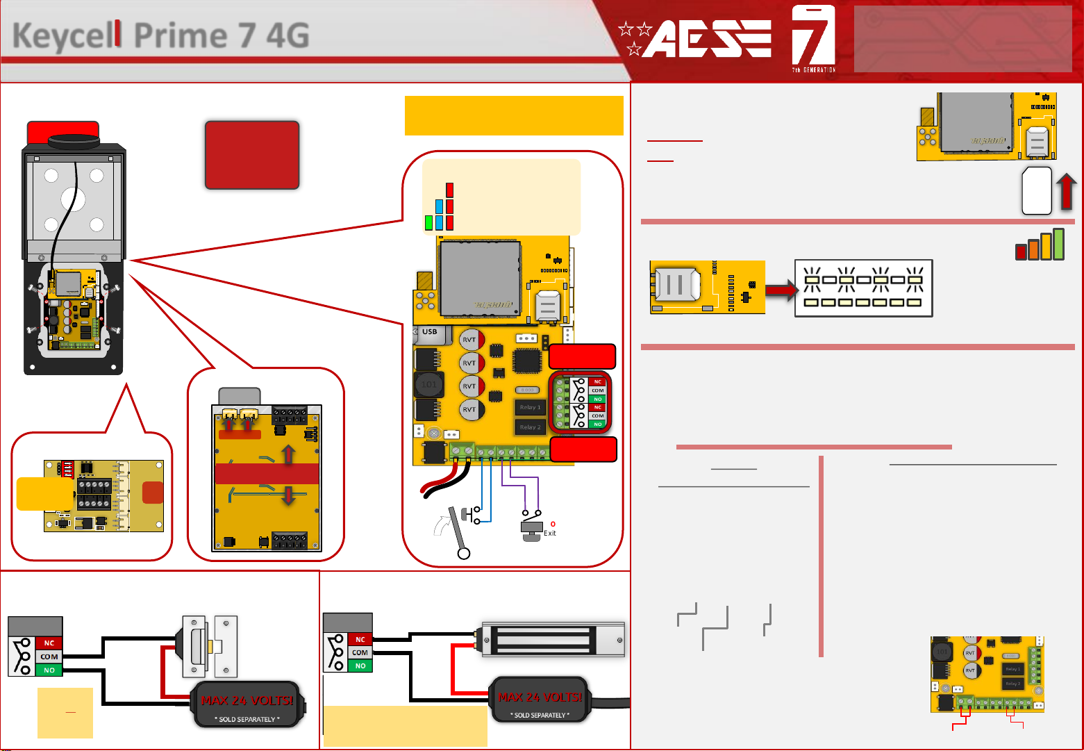
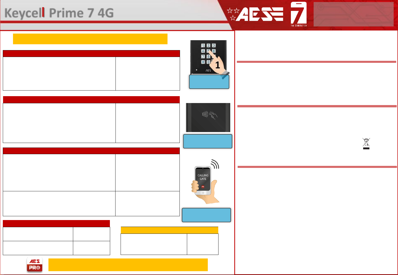
Keypad Code Access
Enter the
programmed code
Prox Card Access
Hold the programmed tag/card
up to the Prox symbol
Dial In Access
Call the SIM phone number
from a programmed CallerID
number. Relay 1 or 2 only
Keypad Programming
Store permanent keypad code (maximum of 250 codes).
X = 1
-8 for relay 1-8.
Code = 4 digit passcode
Time = 1
-9999 seconds, or 0 for latching code.
Name = Name of cardholder (optional) (max 6 characters).
9999
#81Xcode#time#name#
Prox Card/Tag Programming
Store permanent
prox card/tag ID
(maximum of 250 cards/tags).
X=1
-8 for relay 1-8.
Card ID = Prox ID number (fixed 10 digits)
Time = 1
-9999 seconds, or 0 for latching code.
Name = Name of cardholder (optional) (max 6 characters)
9999
#61XcardID#time#name
#
Caller ID
Store permanent caller ID number
(maximum 14 digits long, maximum of 250 numbers).
(Only last 6 digits compared for ID).
Max 8 per message
9999
#72phonenumber#
Switch Caller ID from relay 1 to 2
(permanent caller ID numbers only).
(An
unstored number will still trigger relay 1 via the
default user code 1234, even if Caller ID is set to relay 2)
9999
#54X#
Master Unit Relay Times
Relay 1 time. Default = 1
X = Relay time (1
-9999 seconds)
9999
#50X#
Relay 2 time. Default = 1
X = Relay time (1
-9999 seconds)
9999
#51X#
Auxiliary Unit Relay Times (Optional)
Relay 3
-8 times. Default = 1
Y = Relay Number (3
-8)
X = Relay time (1
-9999 seconds)
9999
#05XY#
Note: Advanced programming available in full manual
Tip: New programming app due to release late 2021
Please note, by installing this product, you are accepting the following warranty terms:
1. The manufacturer’s warranty is a “return to base” 2 year warranty from date of manufacture. This means that any suspected defective
components or items are returned to the manufacturer’s agent for investigation and diagnosis and returned at the cost of the customer.
2. The warranty does not cover, nor is the manufacturer or agent responsible for any of the following whatsoever: Storm damage,
lightning or surge damage, flooding, accidental damage, vandalism or deliberate damage, un-explained corrosion or unusually harsh
environments, failure of telephone networks, future un-interoperability between the product and network providers which cause mal-
function due to changes implemented by the phone providers after manufacture of the product, or that which is outside of control of
the manufacturer (e.g. 2G, 3G switch off, removal or inability to obtain VOLTE service), and damage due to inaccurate installation.
3. The manufacturer in no way accepts liability for any of the following incurred due to a product defect: Cost of attending site,
inconveniences, labor rates, time lost, loss to or damage to property, security breaches, late payment clauses or breaches of any
contracts between the installer and the client.
4. This is a professional install product only. The product is a component of an overall system. Therefore, it is the responsibility of the
installer to certify the safety and compliance of the overall finished system. As soon as this product is fixed to another item, or
connected to another third-party device, then the product has been modified, and compliance with local regulations in the country of
install is strictly the responsibilityof the installer.
5. Re-stocking fees may apply to items returned that are found to be non-defective. Complete units will also attract a re-stocking fee if
returned for credit, regardless if a defect is discovered or not. Re-stocking fees may vary depending on the condition of the item being
returned, and whether it can be determined as in brand new condition. The warranty terms do not entitle customers to an automatic full
refund. For more details on returns procedures and re-stocking fees, contact the agent.
6. Items with physical signs of surge damage are not covered by warranty. Items with visible signs of surge damage will only be covered
by warranty if photographic evidence is provided from site, showing surge protection has been installed.
Full warranty terms and conditions available upon request to AES Technical Department.
Keycell Prime 7 4G - Advanced GSM Keypad/Prox Reader
STILL HAVING TROUBLE?
Find all of our support options such as Web Chat,
Full Manuals, Customer Helpline and more on
our website:
WWW.AESGLOBALONLINE.COM
* ALWAYS TEST THE UNIT ON SITE BEFORE INSTALLATION TO AVOID RE-STOCKING FEE * See full T&C’s on our website

TROUBLESHOOTING
Symptoms caused
Problem/error
Solution
No LEDs on.
The unit will not power up.
Check power supply voltage at intercom is 23.4v DC or more. Cable length from PSU to intercom
should be less than 25 feet and in 14 gauge for longer distances. See guide. Check the fuse.
No green CPU light
The unit powers up but is not
showing network reception
or will not respond to SMS.
A. This means the unit is not able to detect the network for some reason.
-Power off the unit, remove the SIM and check it in a mobile phone to verify it can make a call and
has calling credit if it is a Pay As You Go SIM.
-
Disable any PIN code request if active on the SIM card.
-
Check the SIM is a standard voice capable SIM. If you are unsure, contact your SIM card provider
to verify.
-
Check the reception is medium or good. Poor reception is not sufficient.
-
Power off, remove the SIM, use fine sand paper to lightly sand the SIM pads and contacts on the
GSM unit, lightly bend the contacts upwards so that they make better contact with the SIM and
try again.
-
Check antenna is connected and does not have too many sharp bends on the antenna cable.
The caller ID function
does not work.
Incorrect programming or
poor signal
If your number is a private or number withheld, then it will not work.
-
Ensure the number is programmed as you would normally dial it from another phone.
-
Ensure you have adequate GSM signal at the intercom by sending *20# as a text.
The keypad has no
tones and/or no LEDs
The keypad may not be
properly connected to the
board.
Check the connections from the keypad to the board. If there is no LEDs the red and black power
cable may not be seated properly. If there is no tones from the keypad the white communications
cable may not be seated properly. In each of these instances try reseating them in their respective
ports.
7
INFORMATION
STORED KEYPAD CODES
NORM= Permanent
TEMP= Temporary
PLAN= Time restricted
ACTIVITY LOG
Use this to see who used the intercom
and when. Which pin codes were
used, who used caller ID, who
answered the call.
STORED PROX ID CODES
NORM=Permanentcodes.
TEMP=Temporary codes.
PLAN=Time restricted codes.
SIGNAL STRENTH
Will reply with signal
range 1-31. Min
signal level should be
10 on 4G systems
STORED NUMBERS
I=Dial IN Caller number.
N = Message to follow
E = End of messages
Keycell Prime 7 4G - Advanced GSM Keypad/Prox Reader
STILL HAVING TROUBLE?
Find all of our support options such as Web Chat,
Full Manuals, Customer Helpline and more on
our website:
WWW.AESGLOBALONLINE.COM
* ALWAYS TEST THE UNIT ON SITE BEFORE INSTALLATION TO AVOID RE-STOCKING FEE * See full T&C’s on our website
Reset / Default Unit 1) Power off the unit. (approx 60 secs)
2) Make a link across the terminals
marked OPEN.
3) Switch on power
4) After several seconds the relay will
click.
5) The unit will then clear memory and
be defaulted
6) Remove the link and wait around 20
seconds.
Note: Performing this process will
remove all current programming
including saved users & access codes.
This product is not a complete product until fully installed. It is therefore
considered a component part of an overall system. The installer is responsible to
check that the end installation complies with local regulatory requirements. This
equipment forms part of a “fixed installation”.
STILL HAVING TROUBLE?
Find all of our support options such as Web Chat, Full Manuals, Customer
Helpline and more on our website:
WWW.AESGLOBALUS.COM
+1 (321) 900 4599
24v DC IN OPEN
Terminals
FCC ID : 2ALPX-PRIME7-4GQA
EUT : CellCOM Prime 7 4G
Test Model : PRIME7-PX-IMPK-PED/4GA
Additional Model No. PRIME7-IMP-PED/4GA, PRIME7-PX-IMP-PED/4GA, PRIME7-IMPK-PED/4GA, PRIME7-PX-IMPK-PED/4GA,
PRIME7-AB/4GA, PRIME7-PX-AB/4GA, PRIME7-ABK/4GA, PRIME7-PX-ABK/4GA
Grantee: Advanced Electronic Solutions Global LLC
This device complies with Part 15 of FCC rules. Operation is subject to the following two conditions: (1) this device may not
cause harmful interference, and (2) this device must accept any interference received, including interference that may cause
undesired operation.
Output power listed is ERP below 1GHz for Part 22 and EIRP above 1GHz for Part 24. RF
exposure compliance is addressed for 1.1310 and 2.1091 MPE limits. The antenna(s) used
for this transmitter must be installed to provide a separation distance of at least 20 cm from
all persons.
End Users must be provided with transmitter operation conditions for satisfying RF exposure compliance.
Intercom
*21#
O11:987654321
012:123456789
I1:987654321
I2:123456789
I3:5559991234
I4:99955598767
Intercom
1234#26#
Norm:6897254836R1,
6548974581R2
Temp:
6989874154R1,
6989977415R1
Plan:6985332154R1
Intercom
*23#
0930-05/06/21-code-XX34-R1
1345-05/06/21-CID-543210
2034-04/06/21-user-55987
1632-04/06/21-code-XX89-R2
1244-04/06/21-code-XX98-R2
0840-04/06/21-CID-995555
2109-03/06/21-code-XX34
2101-03/06/21-code-XX89-R2
Intercom
*20#
Firmware:
Keycell Prime v2.1.2
Network mode:4G
Date:18/12/21
Signal level: 18
APN:
Intercom
1234#25#
Norm:1234,5555,
6565,4321
Temp:
4545,7878,9876
Plan:1010,4343
Table of contents