manuals.online logo
Brands
  1. Home
  2. •
  3. Brands
  4. •
  5. AES
  6. •
  7. Test Equipment
  8. •
  9. AES LineSpi User manual

AES LineSpi User manual

AES Line
Spi
OBDII data line monitor and breakout box
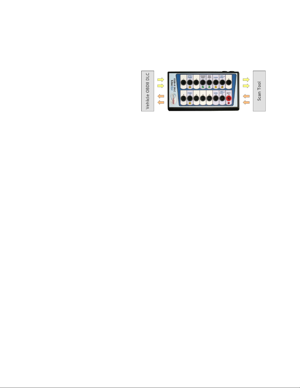
The AES LineSpi is a 'pass through' breakout box for the OBDII DLC (diagnostic link connector). The AES LineSpi offers
easy access to the OBDII DLC for safe probing and testing without the fear of accidental shorting of the wrong pins and
without the need to be a contortionist.
BENEFITS
Eliminate the need to probe at the DLC.
Access each of the 16 DLC pins while scan tool
communicates with vehicle.
LEDs to quickly indicate DLC power or ground
problems.
LineSpi mimics the DLC connector layout for quick
reference.
Use the BOB as an extension cord for your scan tool.
Quick, safe and convenient access to chassis ground and power through the DLC connector.
FEATURES
Uses safety banana sockets that accept all types of 4mm banana plugs including those with safety sheaths.
Socket layout mimics DLC connector.
LEDs to indicate activity:
oYellow LED's light up to show communication with scan tool and protocol identification.
oGreen LED's on grounds (Pin 4 and 5) light up when ground is good.
oRed LED on power lights up when there is power.
4-ft extension cable with DLC adapter connects to vehicle.
Pin 16 input protected with 1.2 amp polyfuse.
USER MANUAL
The user manual can be found in the enclosed CD. The CD should autorun. If it does not use Windows Explorer to find
the INDEX.HTM in the root directory of the CD.
LATEST INFORMATION
To view the latest information of this manual please visit: www.aeswave.com/linespi/manual
CAUTIONS / DISCLAIMERS
This tool is designed for use by automotive professionals. Since neither the manufacturer nor the reseller can control
the application of or installation of this product, their obligation shall be to replace this product if defective and shall
not be liable for any injury, loss, or damage arising from the installation or application of this product. User assumes
all risk in using this product and is therefore cautioned in selecting the product suitable to the intended use. No other
warranty expressed or implied is given unless required by the state in which the product is purchased.
This tool provides easy access to the vehicle data bus lines. Improper use of this tool may result in damage to the
vehicle data communication system and associated circuits and systems.
If you are not sure about what you are doing - don't!
Do not install or remove LineSpi from DLC when vehicle is operational.
Do not install or remove test equipment from LineSpi when vehicle is operational.
Do not switch LineSpi from LED mode to high impedance mode while vehicle is operational.
Do not jumper pins together without understanding the circuit.
Do not use the tool to power up a load device exceeding 1 amp.
Do not place the tool in a spot that may interfere with foot pedal controls.
Do not place a jumper between the power pin 16 and ground pins 4, 5.
Do not modify or attempt repairs of product or use when damaged.
Do not use product for any unintended use.
DO not place product in airbag opening pathway.
LineSpi ‘Diagnostic Mode’ and ‘Activity Mode’
The LineSpi has two operational modes: Activity Mode and Diagnostic Mode. The operational modes allow
the circuit of the LineSpi to be engaged or disengaged. When the circuitry is engaged the yellow LEDs will
flash as changes take place on the corresponding data line. The flashing LEDs offer a visual indication of the
activity on that line.
When switching to diagnostic mode the circuit to the yellow LEDs is electronically disengaged and the yellow
LEDs will no longer flash.
Activity Mode - Smart breakout box
Switch LED is off
Yellow LED circuit is engaged.
oYellow LEDs will flash when data
is present on the corresponding
line.
Diagnostic Mode - Basic breakout box
Switch LED is on
Yellow LED circuit is disengaged.
oYellow LEDs will not flash when
data is present on the
corresponding line.
When to use the Diagnostic Mode
Use diagnostic mode anytime you are performing the following tests:
Resistance testing on the datelines.
Diagnosing power or ground issues.
Using a logic probe to find opens and shorts.
Anytime you want to eliminate as many variables as possible from your testing.
When you don’t need to use the Diagnostic Mode
You can leave the LineSpi in Activity Mode when:
Lab scoping datalines
Jumping datalines
Normal scan tool operation
Recommended Test Procedures
Always repair ground and power problems first! The power supply system is the foundation for the operation
of the vehicle system and the LineSpi. Also, since the LineSpi electronically disengages the circuitry for the
Yellow LEDs it is important to have the LineSpi powered up so it can provide that function. Without power
there will be approximately 4.5 mOhms between any data line and ground.
Diagnosing power and ground problems
The read and green LED offer a basic insight into the integrity of the power and ground system.
For proper testing of power and grounds:
Do not connect your scan tool. Many scan tools tie pin 4 and 5 together.
Set the LinSpi to Diagnostic Mode
Red LED Pin 16
Green LED Pin 4
Green LED Pin 5
On
Off
On
Open in Pin 4 wiring
On
On
Off
Open in Pin 5 wiring
Off
Off
Off
Power
Dim
Dim
Dim
If the LEDs are dim all the times or goes
dim when a scan tool is connected look for
high resistance in the power supply (pin
16) wiring.
Dim
Off
Off
Both grounds are open and there is
feedback from a dataline.
Flash
On, dim or off
On, dim or off
Ensure LineSpi is in diagnostic mode.
Check pin 16 wiring for open circuit.
Questions, Concerns and Repairs
Please call AES for any issues, concerns or to get an RMA for a repair.
Automotive Electronics Services, Inc.
5465 E. Hedges Ave
Fresno CA, 93727
(559) 292-7851

Popular Test Equipment manuals by other brands

LEM HEME ISO 1000 operating instructions

LEM

LEM HEME ISO 1000 operating instructions

ACTiSYS ACT-IR3200M Hardware user manual

ACTiSYS

ACTiSYS ACT-IR3200M Hardware user manual

Keysight U1610A user guide

Keysight

Keysight U1610A user guide

ULTIMATE SPEED 296998 operating instructions

ULTIMATE SPEED

ULTIMATE SPEED 296998 operating instructions

ATEQ VT47 user manual

ATEQ

ATEQ VT47 user manual

IDEAL 61-520 operating instructions

IDEAL

IDEAL 61-520 operating instructions

Chicago Electric 93784 operating instructions

Chicago Electric

Chicago Electric 93784 operating instructions

Tektronix MTS400 Series manual

Tektronix

Tektronix MTS400 Series manual

Megger TRAX user manual

Megger

Megger TRAX user manual

Alcovisor Jupiter instruction manual

Alcovisor

Alcovisor Jupiter instruction manual

ACE INSTRUMENTS ACE View quick start guide

ACE INSTRUMENTS

ACE INSTRUMENTS ACE View quick start guide

Snap-On SVTS2000 manual

Snap-On

Snap-On SVTS2000 manual

Sealey VS402 instructions

Sealey

Sealey VS402 instructions

Tsuruga 8526 instruction manual

Tsuruga

Tsuruga 8526 instruction manual

GRAS 42AA instruction manual

GRAS

GRAS 42AA instruction manual

Larson Electronics SLEDB-110V-DNS-20C Series quick start guide

Larson Electronics

Larson Electronics SLEDB-110V-DNS-20C Series quick start guide

PIE PIECAL 510B operating instructions

PIE

PIE PIECAL 510B operating instructions

Atlona AT-DIS7-PROHD Q&A

Atlona

Atlona AT-DIS7-PROHD Q&A

manuals.online logo
manuals.online logoBrands
  • About & Mission
  • Contact us
  • Privacy Policy
  • Terms and Conditions

Copyright 2025 Manuals.Online. All Rights Reserved.