LEM HEME ISO 1000 User manual

Operating Instructions
Gebrauchsanleitung
Manuel d'utilisation
Guida all’uso
Instrucciones de uso
MULTIFUNCTION INSULATION TESTER /
MULTIFUNKTIONALES ISOLATIONSMESSGERÄT /
APPAREIL DE MESURE D'ISOLEMENT MULTIFONCTION /
TESTER D’ISOLAMENTO A TENAGLIA MULTIMETRO /
TÉSTER DE AISLAMIENTO MULTIFUNCIÓN
HEME ISO 1000 / 2000
ELMES •
••
•HEME •
••
•NORMA
+
1 m A
+
1 mA
OFF
100 V 250 V 500 V
1000 V
600 V
V
CAT III
HEME ISO 1000
R
Hz
Pab
20 00
LIMIT
HOLD
REC MAX
AVG MIN
STORE
RECALL
ZERO
DATA
ACTIVE AC+DC
+
IS O
U
ISO
U
R
1M 40 0 10M 60 0100M 80 0 1G 10001 0 G
V
100k
MkAVkm A
G u
Mk
AVkm
G
K
K
START
HOLD
REC
ZERO
1000 A
M
Ω
Ω
V
A
LIMIT
OFF
10 0
V
250
V
500
V
1000
V
RS 232
600
V
V
C
A
TIII
Digital
Ou tput
HEME ISO 2000
R
Hz
Pab
2000
LI MIT
HOLD
REC M
A
X
A
V
GMIN
STORE
REC
A
LL
ZERO
D
A
T
A
A
CTI
V
E
A
C+DC
+
ISO
U
ISO
U
R
1M 400 10M 600100M 80 0 1G 100010G
V
100k
Mk
A
V
km
A
G u
Mk
A
V
km
G
K
K
ST
A
RT
HOLD
REC
ZERO
2000
A
Ω
V
A
LIMIT
CLR
LOG REC
A
LL
ST OR ESEN D
M
Ω

Order Reference
- 2 -
Order Reference Order No.
HEME ISO 1000 – Multifunction Insulation Tester SI9100Z
HEME ISO 2000 – Advanced Multifunction Insulation Tester SI9301Z
Includes:
• Manual E/G/F/I/ES incl. CE-declaration of conformity
• 1 Pair of test leads with test prods (red/black)
• 1 alligator clip
• 4 pcs. 1,5V AA LR6 MN 1500 batteries
• 1 pouch with carrying belt
Optional Accessories
• PC-software WINLOG V3.0 and special RS 232 cable 60.98.69.010.0
• Probe for surface insulation measurement A604507000
• 1 Pair of test leads with test prods (red/black) A600314205
• 3 alligator clips, black A600917103

Contents
- 3 -
Thank you for buying this product.
Unpacking: check delivery for possible damage during transport.
Keep the packing material for future transportation and check delivery
contents for completeness.
Contents:
1. Safety Regulations ....................................................................................... 4
2. Instrument features ...................................................................................... 6
3. Insertion / replacement of battery and fuse ............................................... 8
4. Getting started / Operating principles ........................................................ 9
5. Basic operation........................................................................................... 10
5.1. Insulation test............................................................................................ 10
5.2. Resistance measurement / Continuity ......................................................12
5.3. Voltage measurement............................................................................... 14
5.4. Current measurement ............................................................................... 16
6. Advanced functions ................................................................................... 18
6.1. Determining the Dielectric Absorption ratio Rab in Insulation test..............18
6.2. HOLD / SMART HOLD.............................................................................. 20
6.3. LIMIT (Alarm)............................................................................................20
6.4. REC (Record) ........................................................................................... 22
6.5. ZERO........................................................................................................22
6.6. Back-light ..................................................................................................22
7. Memory (HEME ISO 2000) .......................................................................... 23
7.1. Memory Saving/Recalling screens............................................................ 23
7.2. Memory – data logging.............................................................................. 24
7.3. Logged data output to a PC ......................................................................26
8. POWER ON functions................................................................................. 27
9. Technical Data ............................................................................................ 34
10. Upkeep and Maintenance........................................................................... 39
11. Other products............................................................................................ 40

Safety Regulations
- 4 -
1. Safety Regulations
• Safety warnings and precautions must be read and understood before the
instrument is used. They must be observed during use. Operating
electrical devices implies that parts of the device carry dangerous
voltages. Disregarding warning notices may lead to serious physical
injury and material damage. For example: touching the key tips.
• This measuring device is only to be installed and operated by qualified
personnel and according to the technical data in compliance with the safety
precautions and regulations set forth below. Additionally, the use of this
equipment requires compliance with all legal and safety regulations pertaining
to each specific application. Similar regulations apply to the use of accessories.
• Test leads, prods and crocodile clips must be in good order; clean, and with no
broken or cracked insulation
• Replacement fuses must be of correct size, type and rating
• It can be assumed that safe operation is no longer possible if the device
- shows visible damage,
- has been exposed to unfavourable conditions (e.g. storage beyond
the permissible climatic limits without adaptation to the ambient
climate, dewing etc.) or to
- has been exposed to major strain during transport (e.g. been dropped
from some height without visible external damage etc.).
• No measurements must be performed on unprotected measuring circuits.
• Avoid working alone.
International Elecrical Symbols used on the instrument:
Caution! Refer to the instructions before using this instrument.
Equipment protected throughout by Double insulation (Protection Class II)
Equipment complies with relevant EU Directives
Dangerous voltage
COM Ground
Qualified Personnel are persons familiar with the setting up, installation, starting off
and operation of the device and possess a formal qualification required for such
activities.

Safety Regulations
- 5 -
The instrument has been designed to comply with IEC1010-2-032 Installation
Category (Overvoltage Category) III 600V Pollution degree 2 and
UL 3111-1. The instrument conforms with the EEC Low Voltage Directive
73/23/EEC and 93/68/EEC.
IEC 1010 is a safety standard which has the following features:
• Installation categories I to IV relate the maximum working voltage to overvoltage
transients that can be expected in the measuring environment. For the
instrument, 600V CAT III, the maximum expected transients must not exceed
6kV peak.
• In a pollution degree 2 environment the internal design of the instrument can
cope with transient conductivities due to condensation.
Safe operation of the instrument is the responsibility of the operator who
must be suitably qualified and/or authorised as defined above. Users of this
equipment and or their employees are reminded that Health and Safety
Legislation requires them to carry out valid risk assessments of all electrical
work, so as to identify potential sources of electrical danger and risk of
electrical injury such as from inadvertent short circuits. Where the
assessments show that the risk is significant, then the use of fused test leads
constructed in accordance with the HSE guidance note GS38 ‘Electrical Test
Equipment for use by Electricians’ is advised.
If the instrument is used in a manner not specified by the manufacturer, then the
protection provided by the equipment may be impaired.
Maximum Safe Voltage
Current :- 600V MAXIMUM AC RMS or DC between uninsulated conductor and
ground and maximum frequency of 1kHz. This limitation applies to unisulated
conductors only.
Voltage:- 600V MAXIMUM AC RMS or DC between live conductor and ground.
600V MAXIMUM AC RMS or DC between V and COM terminals and a maximum
frequency of 1kHz.
Important Information
• The instrument is intended for indoor use only.
• Do not attempt to take any measurement of current or voltage higher than the
maximum range of the instrument.
• The unit is not hermetically sealed and should NOT be brought into contact with
surface water.
• Frequently inspect the test leads and the instrument for damage. If the
instrument is physically damaged or does not function properly, it should not be
used.
USE ONLY SUITABLY RATED VOLTAGE TEST LEADS TO IEC 1010-2-031.
(600V CAT III Pollution Degree 2).

Instrument features
- 6 -
2. Instrument features
This instrument has been manufactured complying with Quality Assurance System DIN
ISO 9001. The compliance with the current applicable EMC-regulations is indicated by
the CE-sign and markings on the instrument.
THE HEME ISO series – is unique in providing 3 instruments in 1, a compact
hand-held insulation tester, a TRMS current clamp and a TRMS multimeter. The
instrument is the ideal tool for the inspection of new electrical installations and
the maintenance and troubleshooting of existing plant and equipment. The ISO
2000 offers advanced features for the documentation of safety tests and the
identification of trends and intermittent faults.
Main features:
• Easy to use handheld design measuring V, A, Ω, MΩ, Hz
• Large dual display with bright EL backlight and bargraphic
• Insulation measurements up to 20 GΩwith 100, 250, 500 and 1000V test
voltages and display of test current
• True RMS current and voltage measurement with display of AC, DC and AC+DC
values
• Auto ranging resistance measurement to 200kΩwith 200mA low resistance test
and lead compensation
• Continuity test with adjustable thresholds and fast responding buzzer
• LIMIT (alarm) to quickly and reliably identify fault conditions
• REC function for MIN, MAX, AVG values
• General protection against external voltages without fuse damage
Additional features HEME ISO 2000
• Simple storage of up to 350 insulation test results for on screen viewing or PC
download
• Internal data logging of current and voltage (up to 1000 readings) for trend and
intermittent fault analysis
• Optional WinLog software and interface for PC connectivity, data download and
insulation resistance logging
• On screen display of Polarisation Index and Dielectric Absorption Ratio for
insulation quality
• Extended current range to 2000A

Instrument features
- 7 -
RISO
OFF
100 V 250 V 500 V
1000 V
200mA
600 V
1 kA
R
RS 232
600 V
COM
1 mA
V
CAT III
Digital
Out put
ISO Clamp II
200G
20 k
R
Hz
200
LIMIT
HOLD
REC MAX
AVG M IN
STORE
RECALL
ZERO
DATA
ACTIVE AC+DC
+
ISO
U
ISO
U
R
1M 400 10M 600100M 800 1G 100010G V
100k
MkAVkm A
G
u
MkAVk
m
G
K
K
START
HOLD
REC
ZERO
A
B
C
D
E
F
GH
AJaw opening lever
BRotary switch for function selection
CClamp-on jaws for current measurement
DDual parameter display with backlight
EKeyboard
FDigital output – RS 232 (ISO 2000)
G
,
HTest lead in
p
ut terminals
Rotary switch functions
A
B
C
D
E
F
H
G
A
B
C
D
E
F
H
G
1.1. Keyboard
ISO 1000 / 2000
Display change key
ZERO. Amps Zero, relative values, test lead
compensation
REC mode: Max, Min, Average
Cursor control in input mode (digit select) /
RS232 output
START Measurement in RISO, otherwise HOLD
Continuity in resistance / Backlight ON for
30s (2secs press)
Activate LIMIT
Increment selected digit
OFF Position direct power OFF switching
U ISO = 100 V test voltage
U ISO = 250 V test voltage
U ISO = 500 V test voltage
U ISO = 1000 V test voltage
Continuity test activated by key press in Ω200mA
Resistance Measurement 20Ω... 200 kΩ
Voltage AC/DC True RMS, Frequency Hz
Current AC/DC True RMS Frequency Hz

Insertion/replacement of battery and fuse
- 8 -
3. Insertion / replacement of battery and fuse
Replacement with other than the specified batteries will invalidate the warranty.
Fit only Battery Type 1.5V Alkaline MN1500, IEC LR6 or equivalent x 4.
The low battery indicator will appear on the LCD display to indicate that the
minimum operating battery voltage has been reached.
To change the batteries, see Fig.1 Battery replacement below
• Switch off the instrument
• Undo the retaining screws (Aand B) on the battery cover and lift the cover clear
of the unit.
• Replace the used batteries, take care of the polarity. If no lamptest is executed,
please remove batteries immediately and check for correct polarity.
• Ensure the battery cover is replaced and the locking screws tightened, before
further use.
• Replace Fuse Cwith the same type FF 1,25A 6,3x32 660V /30kA
Fig. 1 Battery replacement
Discard used batteries according to manufacturer’s instructions.
SAFETY WARNING
Before removing the battery cover, make sure that all external voltages are
disconnected from the instrument. For certainty remove all leads and
unclamp the instrument.
C

Getting started/Operating principles
- 9 -
4. Getting started / Operating principles
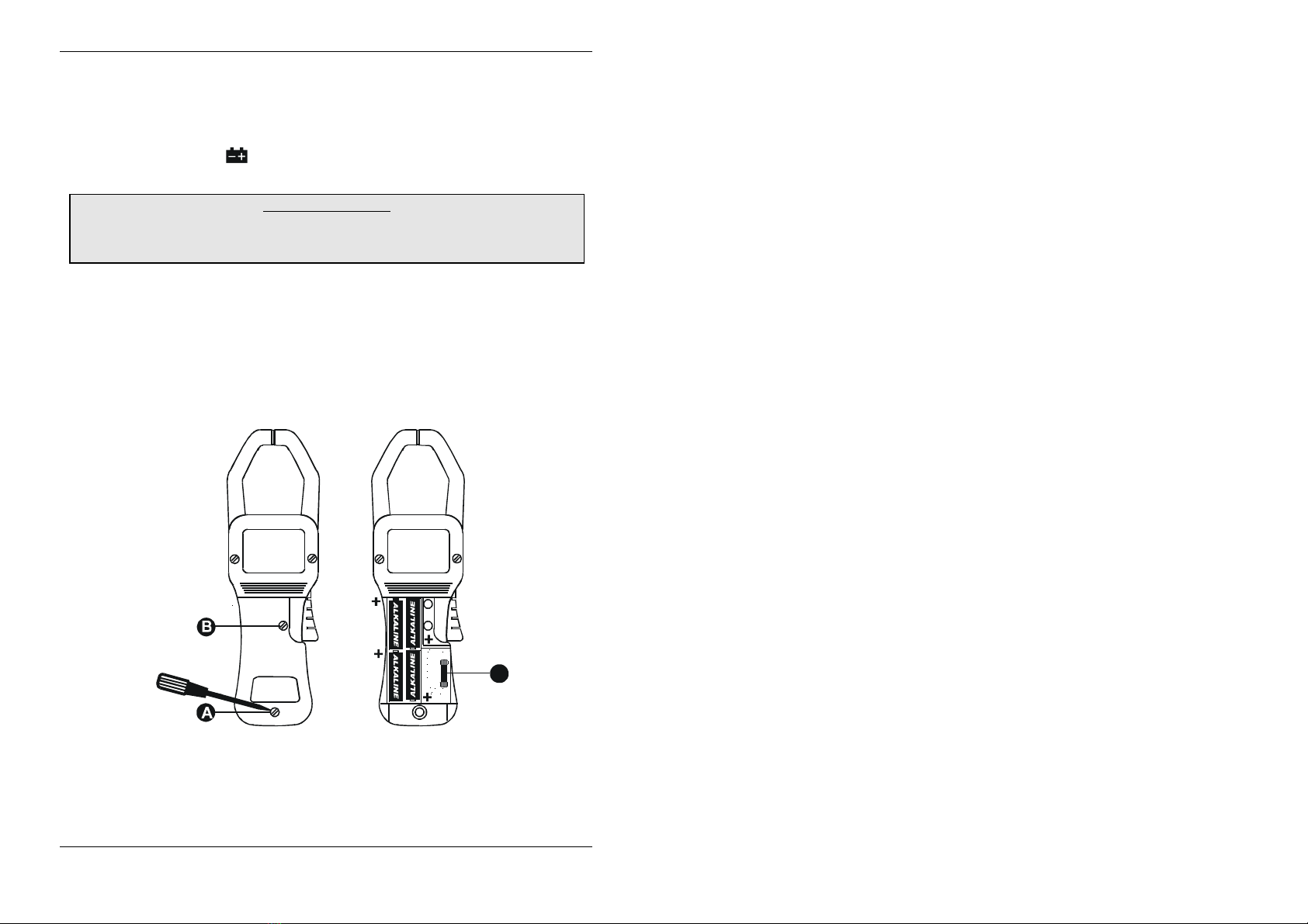
Examine the instrument carefully, familiarizing yourself with the layout of the input
terminals, rotary switch, pushbuttons and display. Notice the WARNING information
and summary of power-on options.
If you have used a multimeter and a current clamp before, simply examining your
meter will probably give you a good idea how to use it. The following procedure is an
overview of how to take basic measurements.
Two principal functions exist depending on the selected rotary switch position:
Continuous running measurement functions as volts, amps or standard
resistance/continuity tests and insulation tests, where the measurement has to be
started with the button. The test voltage depends on the rotary switch
position ranging from 100V up to 1000V. The functionality of the button
depends on the selected mode. Start can either start a measurement in the
insulation test or for the continuous mode functions (V, A, ,Ώ) it enables the
HOLD mode, where the actual displayed values in the LCD-display is frozen. In
insulation test after pressing more than 10 s instrument enters continuous
mode until is pressed again.
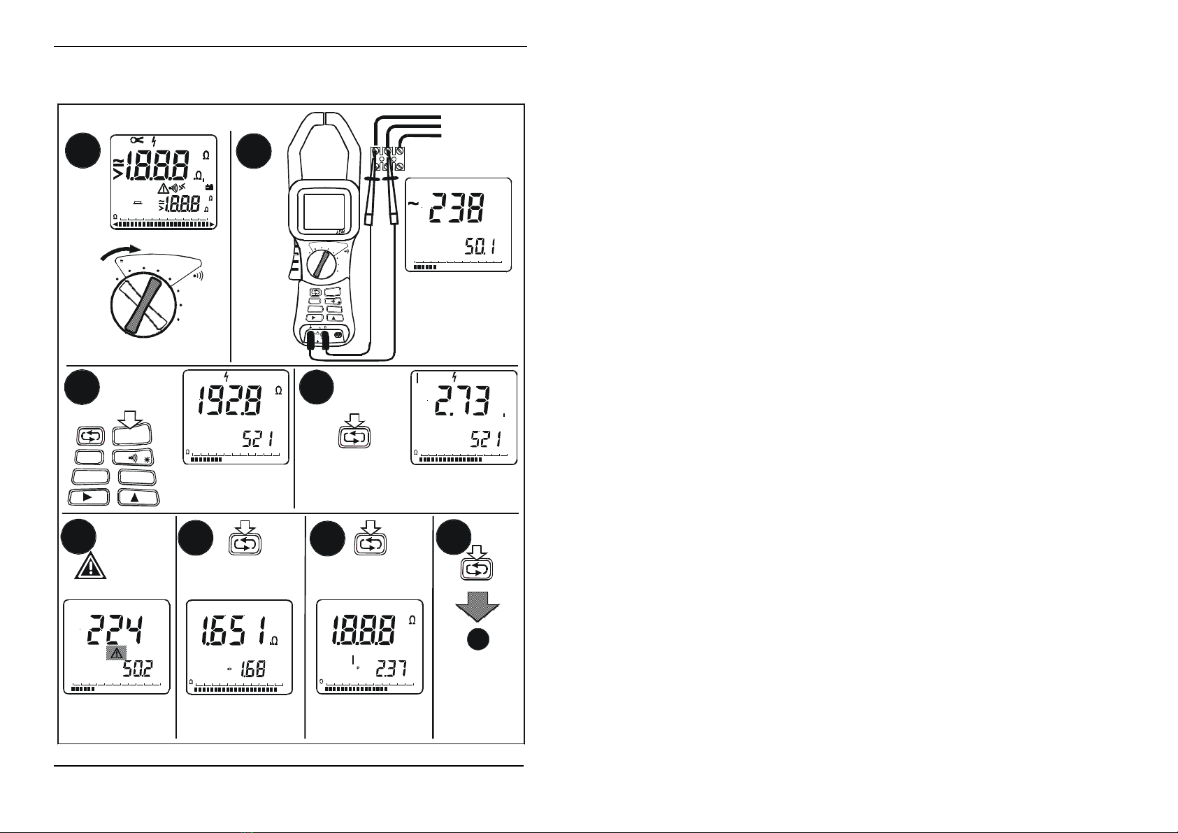
1. Insert the test leads in the appropriate input terminals COM and V Ώ
2. To turn the instrument on and select a function, turn the rotary switch from OFF to
the appropriate switch position. All segments on the liquid-crystal display (LCD)
will turn on for 3 seconds, then the meter is ready for normal operation.
The button switches between different screens displaying more data about
the measurement being made. For example, switching between limit or
frequency display and the different AC signal parts like RMS, TRMS.
3. To select an additional operation, press the appropriate pushbuttons underneath
the rotary switch as described in the items below.
• In the resistance measurement function the button enables the continuity
function. That means the continuity symbol in the LCD-display is activated and
the buzzer is also activated if the continuity limit is exceeded. The limit value
(trigger) can be set between 0.2Ωand 50Ωand defaults to 2Ω.
• For more advanced functions see section 6 of this manual
4. To take a measurement, use the test lead probes to make the proper contacts.
Remember, insert the instrument in the circuit in parallel for insulation, voltage
and resistance and use the clamp for current measurements. Read the
measurement on the display. If you did not manually fix the highest range (by
using the button while power on), the range that provides the best resolution
is automatically selected.

Basic operation
- 10 -
5. Basic operation
5.1. Insulation test
1 mA
OFF
100
V
250
V
500
V
1000
V
RS 232
600 V
CAT III Dig i t al
Ou tpu t
HEME ISO 2000
START
HO LD
REC
ZERO
2000 A
M
Ω
Ω
V
A
LIMI T
CLR
LOG RECALL
STORESE ND
R
U
ISO ISO
U
+
V
OFF
100 V 250 V 500 V
1000 V
M
Ω
Ω
V
A
L2
L1
L3
R
Hz
0
AC+DC
U
1M 10M 100M 1G 10G
V
100 k
V
R
0
ISO
1M 10M 100M 1G 10G100k
G
R
0
ISO
1M 10M 100M 1 G 10G100k
M
0
ACTIVE
ISO
1M 10M 100M 1G 10G100k
M
V
0
A
CTI
V
E
A
C+DC
ISO
1M 10M 100M 1G 10G100k
A
u
V
1
R
ISO
3
2
6
5
3
R
Hz
Pab
2000
LI MI T
HOLD
REC MAX
AVG MI N
STORE
RECALL
ZERO
DATA
ACTI VE AC+DC
+
ISO
U
ISO
U
R
1M 400 10M 600100M800 1G 1000 1 0G
V
100k
MkAVkm A
G u
MkAVkm
G
K
K
R
Hz
Pab
2000
LI MI T
HOLD
REC MAX
AVG MI N
STORE
RECALL
ZERO
DATA
ACTI VE AC+DC
+
ISO
U
ISO
U
R
1M 400 10M 600100M800 1G 1000 1 0G
V
100k
MkAVkm A
G u
MkAVkm
G
K
K
4
START
HOLD
ZERO
CLR
REC LIMIT
LOG RECALL
STORESEND
R
ISO
, U
ISO
R
ISO
, U
ISO
I
ISO
,U
ISO
R
ISO
, R
ab
(>60s) R
ISO
,I
p
(>10min)
U > 50 V
Hz
0
A
C+DC
U
1M 10M 100M 1G 1 1 0G
V
100k
V
7
8

Basic operation
- 11 -
Select the insulation test voltage with the rotary switch
Connect test leads and check for external voltages.
If the external voltage is greater than 10% of the test voltage, it is not
possible to make an insulation test for safety reasons
Press the key until the displayed insulation resistance value is stable.
Pressing the START button for more than 10 seconds enables continuous
insulation resistance measurement
Attention: The
ACTIVE
annunciators indicate that the instrument is outputting
dangerous high voltages
Press the key to display the insulation test current I
Press the key again to show the Absorbtion factor Rab (available after
60s of continuous insulation test)
Press the key again to show the Polarisation factor IP(available after 10
minutes of continuous insulation test)
Press the key again to return to the main screen showing the insulation
resistance
Release the key or press this key again to stop continuous
measurement. Wait until external capacitors are unloaded before
disconnecting test prods
will flash in case of external voltages greater than 50V

Basic operation
- 12 -
5.2. Resistance measurement / Continuity
1 mA
OFF
100 V 25 0
V
500
V
1000
V
RS 232
600 V
CAT I I I Digital
Output
H EM E IS O 2000
STA RT
HOLD
REC
ZER O
2000 A
M
Ω
Ω
V
A
LI MIT
CLR
LOG RECALL
STO R ESE N D
5
START
HOLD
ZERO
CLR
REC LIMIT
LOG RECALL
STORESEN D
R
START
HOLD
ZERO
CLR
REC LIMIT
LOG RECALL
STO RESEND
V
+
OFF
100 V 250 V 500 V
1000 V
M
Ω
Ω
V
A
R
A
CTI
V
E
ZERO
R
R
ACTIVE
R
ZERO
+
R
3
4
1
R
R
Hz
Pab
200
0
LIMIT
HOLD
REC MAX
AVG MI N
STORE
RECALL
ZERO
DATA
ACTIVE AC+DC
+
ISO
U
ISO
U
R
1M 400 10M 600100M 800 1G 10001 0G
V
100k
MkAVkm A
Gu
MkAVkm
G
K
K
2
R
x
SEND
STORE
LIMIT
REC
A
LL
LIMIT
REC
A
LL
ZERO

Basic operation
- 13 -
Select the resistance measuring mode by turning the rotary switch to the Ω
position.
Connect the test leads to the test object and check for external voltages.
If the external voltage is greater than 3V a warning symbol is displayed. Even
if a live voltage is present, the fuse will not be damaged.
Test lead compensation can be activated by connecting the teads together
and pressing the key. The instrument is now in a Relative measurement
mode indicated by the ZERO anunciator on the display. This mode is also
valid for continuity testing. The actual value of compensation Rzero is
indicated on the small display.
Press the key to activate the continuity test with a 200mA test current
Adjust continuity level using the key from 0,2 to 50 Ohm,
selects the digit, increments the digit
Pressing the key again exists the LIMIT setting mode and activated the
new limit.
For continuity testing with added fuse protection against live voltages see section
6.3 LIMIT.

Basic operation
- 14 -
5.3. Voltage measurement
1 mA
OFF
100 V 250 V 50 0 V
1000 V
M
Ω
Ω
V
A
OFF
100
V
250
V
500
V
1000
V
RS 232
6 00 V
V
CATIII Digital
Output
HEME ISO 20 00
START
HOLD
REC
ZER O
2000 A
M
Ω
Ω
V
A
LIMI T
CLR
LOG RECALL
STORESEN D
+
L2
L1
L3
Hz
2000
A
C+DC
U
400 600 800 1000
V
V
Hz
2000
AC
U
400 600 80 0 1000
V
V
Hz
2000
U
400 600 800 1000
V
V
2000
LIMIT
AC
U
U
400 600 800 1000
V
V
V
DC
2000
LI MI T
A
C
U
U
400 600 800 1000
V
V
V
UTRMS
A
C+DC
12
START
HOLD
ZERO
CLR
REC LIMIT
LOG RECALL
STORESE ND
3
U RMS AC
4
UDC
6
5
U AC, Limit MIN U AC, Limit MAX
SEND
STORE
LIMIT
RECALL
2x
LIMIT
REC
A
LL
23
4
R
Hz
Pab
200
0
LIMIT
HOLD
REC MAX
AVG MI N
STORE
RECAL L
ZERO
DATA
ACTIVE AC+DC
+
ISO
U
ISO
U
R
1M 400 10M 6001 00M 800 1G 100010 G
V
100k
MkAVkm A
G u
MkAVkm
G
K
K
V
VV
7
SEND
STO RE

Basic operation
- 15 -
Select the voltage measurement function by turning the rotary switch to the
V position
Connect test leads to the voltage source – the instrument displays the True
RMS value and the frequency of any AC component
Pressing the key cycles the display through the AC and DC
components of the voltage. The analog bargraph always shows the True
RMS (AC+DC) value
To activate the LIMIT (alarm) function press the key. To set the lower
limit press the key again and use the to selects the digit and
the key to increment the digit. When in this mode pressing the
first turns the lower limit value off completely. To set the higher limit press
the key and use the arrow keys as above. To activate the LIMIT
function press the key again.
To deactivate the LIMIT (alarm) function turn the rotary switch to a new
position

Basic operation
- 16 -
5.4. Current measurement
1 mA
1 mA
OFF
100 V 250 V 500 V
100 0 V
M
Ω
Ω
V
A
OFF
100
V
250
V
500
V
1000
V
RS 232
600 V
V
CAT III Digital
Output
H EM E ISO 2000
START
HOLD
REC
ZER O
2000 A
M
Ω
Ω
V
A
LIMI T
CLR
LOG RE CAL L
STO R ESE N D
+
L2
L1
L3
LIMIT
AC
A
Hz
DC
A
Hz
AC
A
1
3
4
2
6
5
I DC
I AC, Limit MIN I AC, Limit MAX
SEN D
STORE
LIMIT
RECALL
2x
LIMIT
REC
A
LL
23
4
START
HOLD
ZERO
CLR
REC LIMIT
LOG RECALL
STORESEND
R
Hz
Pab
2000
LIMIT
HOLD
REC MAX
AVG MI N
STORE
RECALL
ZERO
DATA
ACTIVE AC+DC
+
ISO
U
ISO
U
R
1M 400 10M 600100M 800 1G 1000 10G
V
100k
MkAVkm A
G u
MkAVkm
G
K
K
Hz
A
C+DC
A
I RMS AC
LI MI T
A
C
A
k
A
SEN D
STORE
7
7
ITRMSAC+DC

Basic operation
- 17 -
Select the current measurement function by turning the rotary switch to the A
postion. The instrument will go into an autozero mode for- 10 seconds until
the ZERO symbol disappears.
Clamp around a single current carrying conductor. The instrument displays
the True RMS value of the current and the frequency of any AC component
Pressing the key cycles the display through the AC and DC components
of the current. The analog bargraph always shows the True RMS (AC+DC)
value
To activate the LIMIT (alarm) function press the key. To set the lower
limit press the key again and use the to selects the digit and the
key to increment the digit. When in this mode pressing the first
turns the lower limit value off completely. To set the higher limit press the
key and use the arrow keys as above. To activate the LIMIT function
press the key again.
To deactivate the LIMIT (alarm) function turn the rotary switch to a new
position

Advanced functions
- 18 -
6. Advanced functions
6.1. Determining the Dielectric Absorption ratio Rab in
Insulation test
The Rab value is only available if the insulation test is continued for
more than 1 minute. The Rab value gives an indication of the quality
of the insulation. It is calculated using the following formula:
)30(
min)1(
sR
R
R
ISO
ISO
ab =
Measuring procedure:
Connect instrument to the installation/equipment with the
supplied test leads.
Select the required Insulation test voltage with the rotary switch.
Initiate the test by pressing the START key, hold this key down for 10
seconds to activate continuous measurement.
The test can be terminated anytime by pressing „START“ again.
(ATTENTION: The measuring voltage is applied all the time!).
While the test is in progress the annunciators
ACTIVE
are displayed
as a warning of the high tension at the measuring terminals.
After a minimum period of 1 minute indicated by frequence change of
the buzzer signal warning every 5 s the presence of high voltages.
The Rab value can be displayed using the key to select the Rab
screen.
The key toggles between Rab, the latest measured value of RISO
and the actual measuring voltage UISO.
Measured value evaluation :
Rab >1.25 means: good insulation and Rab < 1.1 signifies poor
insulation.
CAUTION: The installation / test specimen must be set potential-free
prior to measurement!
In case of external voltages above 10% of the selected test voltage
(10V, 25V, 50V and 100V) the measurement is blocked.

Advanced functions
- 19 -
Determining the Polarization Index Ip
The Ipvalue is only available if the insulation test is continued for
more than 10 minutes. This again is indicated by a frequence change
of the 5s buzzer alarm. The Ipvalue gives an indication of the qulaity
of the insulation. It is calculated using the following formula:
ΙpISO
ISO
R (10min)
R(1min)
=
Measuring procedure:
Connect instrument to the installation/equipment with the
supplied test leads.
Select the required Insulation test voltage with the rotary switch.
Initiate the test by pressing the START key, hold this key down for 10
seconds to activate continuous measurement.
The test can be terminated anytime by pressing „START“ again.
(ATTENTION: The measuring voltage is applied all the time!).
While the test is in progress the annunciators
ACTIVE
are displayed
as a warning of the high tension at the measuring terminals.
After a minimum period of 10 minutes indicated by a beep the Ipvalue
can be displayed using the key to select the Ipscreen.
The key toggles between Rab, Ip,the latest measured value of
RISO and the actual measuring voltage UISO.
Measured value evaluation :
Rab >1.25 means: good insulation and Rab < 1.1 signifies poor
insulation.
CAUTION: The installation / test specimen must be set potential-free
prior to measurement!
In case of external voltages above 10% of the selected test voltage
(10V, 25V, 50V and 100V) the measurement is blocked.

Advanced functions
- 20 -
6.2. HOLD / SMART HOLD
HOLD for the HEME ISO 1000 immediately freezes the displayed
values
SMART HOLD for the HEME ISO 2000 allows hands free
operation by only triggering the HOLD function above a preset
threshold set at approximately 10% of the measuring range.
Activation of SMART HOLD functions: Press the HOLD key and
apply the test leads or the current source to be measured, the
HOLD symbol will flash. Once a measurable signal is present the
instrument beeps and the Hold function becomes active freezing
the display. To reactivate the HOLD function while the
instrument is still connected press the HOLD key again.
Alternatively to reactivate the HOLD disconnect the source being
measured and then reapply the source. The last value to be
measured will be held until a new signal is detected which is
above the default threshold.
To switch the SMART HOLD function off, press the HOLD key for
2 seconds.
The HOLD function operates on whatever parameter is being
displayed in the upper digits block; i.e., one of AC, TRMS or DC.
It is not applicable to insulation measurements
6.3. LIMIT (Alarm)
The limit (alarm) function is activated with the key and can
be used to detect when a value exceeds or falls below user
definable thresholds.
Exceeding the limit values is reported on the display and by
the buzzer (the lower limit with display "<LIMIT" and low
frequency sound, the upper limit with display ">LIMIT" and
high frequency sound).
The limits can be changed by pressing the key again.
“Crossed limits” are supported for testing if a value is within a
certain range. The limit and appropriate >/< symbols are
displayed. They are not flashed. If the upper limit value is
placed below the lower limit value, the measured values
between the two limits are displayed with both annunciators
“<>" on and reported acoustically.
Limit values are displayed in the smaller display when in the
change limit mode. The limit values can be changed using
the and arrow keys. The high or low limit can be
turned off completely by pressing the the key after
activating the limit display – the display shows OFF..
This manual suits for next models
1
Table of contents
Languages:
Other LEM Test Equipment manuals