AETA ScoopFone HD-R User manual


2
Front panel & controls
1. Level control: This potentiometer
controls the microphone level.
2. Mute indicator: The LED turns red
when the microphone input is
enabled.
3. Mic button : To enable/disable
microphone input
4. Microphone level status: The
microphone has a 3 segment
indicator (Over -20dBFS / -12dBFS / -
3dBFS).
5. OLED Screen
6. Navigation keys: Use the Esc key to
access the configuration menu. Use
the Up and Down keys to navigate
between choices and use the OK
key to validate menu choices or
messages.
7. Function key: Used in combination
with other keys, it gives access to
functions marked in blue. It is active
for 5 seconds. This key is called Fn
hereafter.
1
2
3
4
5
6
5 7 8
910 12 13 14
15 16 17 18 19
20
21
11

3
8. Microphone gain: When Fn is
enabled, use key 4to increase and
key 7to decrease gain of the
microphone.
9. Network auto: When Fn is enabled,
use this key to select the automatic
network selection (2G & 3G).
10. Network 3G: When Fn is enabled,
use this key to force the 3G network
(See §: To get HD).
11. Buzzer shortcut: When Fn is
enabled, use this key to enable or
disable the buzzer.
12. Network indicator: The LED turns
blue when 3G network is reached.
13. Book key: Press Book key to access
one of 9 memories or to save
current phone number into a
memory. Or access to your SMS
with in Fn mode
14. SIM Card slot
15. Communication indicator:
The LED turns green when the
communication is established.
16. Call key: Use the Green phone key
to initiate a call.
17. Power indicator: The LED turns red
when the battery is charging from
an external power supply and green
when it is fully charged.
18. Alarm indicator: The LED turns red
when an alarm occurs (PIN request,
SIM missing, no network…). Details
of the alarm are shown on the
display.
19. Hang up key: Press the Red phone
key to release a connection. Holding
it for 2 seconds to start the
ScoopFone
20. Headphone socket: 3.5mm stereo
jack.
21. Headphone level: Handles the level
of the headphone connected on the
ScoopFone.

4
OLED Screen
1 2 3 4 5
6
7
1. Network level indicator: 5 levels.
2. Function key indicator:flashing
when blue functions are enabled by
the Fn key.
3. SMS reception indicator: stay
displayed until all the new SMS are
read, using Fn and Book keys.
4. Microphone power indicator: 48V
phantom.
5. Buzzer indicator
6. Mobile network operator name
7. Transmit audio level: From -30 dBFS
to 0 dBFS.
INTRODUCTION
We advise you to read this quick
guide to start using the ScoopFone in
a very short time. For more detailed
information on each step, do not
hesitate to consult the full user
manual on our web site:
www.aeta-audio.com
The easy-to-use ScoopFone is
designed for the needs of journalists.
The 7 kHz wideband sound quality
allows the full signature character of
the reporter’s voice to be heard,
leading to greater audience
involvement and loyalty
In this guide, we assume most of the
main basics are known and that you
already have a microphone and a
headphone connected.

5
SETTING IT UP
Powering
Before switching on the ScoopFone,
you need to have an external DC
power connected on the DC jack.
External power supply
You can use an external power DC.
ScoopFone needs 12V DC but is able
to work with voltage from 10 to 16V /
1A minimum.
Connector: XLR4 (pin 1:-, 4:+)
Antenna
The ScoopFone uses SMA bulkhead
female connectors. You must
connect one antenna on the rear
panel.
SIM card
To establish communication, you
should have a SIM card from a
telecom operator. ScoopFone
supports standard SIM size, use a
card adaptor to support micro SIM
Card (Contact your dealer for more
details).
To insert the SIM card into the slot,
follow the orientation on the front
panel (downward contact, insert the
mitred corner facing forward). As the
SIM card holder is a push-push
holder, you should push the SIM card
to extract it.
Warning: For new SIM card, use a
mobile phone to activate your prepaid
SIM card and disable second call.
6
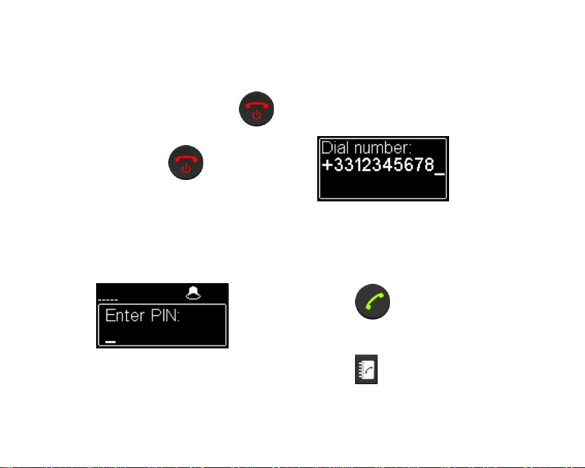
SET A CALL
Switching ScoopFone on /off
To switch ScoopFone on, press
2 seconds.
To turn it off, press key 2s, a
confirmation message will be
displayed. Press OK to switch off or
ESC to cancel.
Enter your PIN code
If the PIN code is enabled on your
SIM CARD, you should enter it and
validate with OK.Pin code can be
saving by menu.
Set a call
Enter directly your phone number
with the digital keypad.
Press the 0key twice to have the
international +symbol.
Press UP or DOWN to erase last
digit.
Press key to launch the call.
Or
Press key to save this number
into one of the 9 memories.

7
Set a call with a memory
Press key and enter the number
of requested memory from 1 to 9.
The number appears and you can
establish the communication with the
key
Or
-Cancel by ESC /
-Modify the phone number by
pressing UP or DOWN
Redial
Press the key twice to redial
the last phone number
Adjust your microphone/line
level
Turn ON the mute LED indicator with
the mute key .
Set the Level control (1), on middle
position, white dot of the button in
topmost position.
Make a test with your microphone.
If the level is too high or too low on
the display and LED bargraph, enable
Fn mode and press the key 4to
increase or the key 7to decrease the
gain of the microphone until you get
the right level.
Hang up
Press twice to hang up.

8
To get HD Voice
To get a HD Voice connection, some
conditions are requested:
-Both devices in the connection
must support HD voice
-Support of HD voice by your mobile
operator’s network
-Very often, only the 3G network
supports HD voice. This depends
on the country or area, and the
operator.
For this last reason, having a
connection on 3G can be a condition
to get HD Voice. In this case, the 3G
LED is a useful indication that HD
Voice is possible. In addition, it is
possible to force operator on 3G
mode: enable Fn mode and press key
3.
To restore the automatic network
selection, enable Fn mode and press
key 2.
How to turn on/off the buzzer
Enable Fn mode and press # key to
change the buzzer state.
When the buzzer is off, the buzzer
icon on the display is stroked.
SMS management
Enable Fn mode and press key
to show the list of received SMS.
If you have many, press OK to read
the selected SMS. Press Esc key to
keep it, otherwise OK to delete it.
9
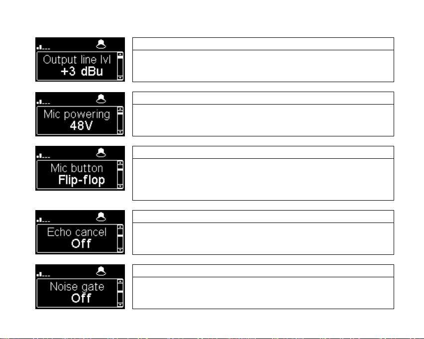
MENU
Line output level adjustment
You can select maximum output level from -9dBu to
21dBu
Microphone phantom power
You can enable 48Volts phantom power
3 functions on Microphone/line button
Flip-flop : change the input state between enabled and disabled
Push to talk : Key should be keep pressed to enable the input
Cough key : The key should be keep pressed to disable the
input
Echo cancel
You can enable a local echo cancellation
Noise Gate configuration
You can enable noise suppression on the mixed signal
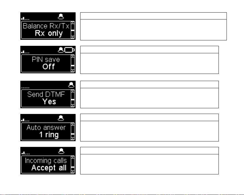
10
Audio Balance between Send and Receive
Available settings: Rx only, Rx +1/3Tx, Rx+Tx
Rx = Reception from the network
Tx = Transmission to the network
PIN save
On or Off
If a wrong pin is enter, PIN save option will switch
to off. The PIN is saving only if it is correct.
Enable DTMF
Capability to send DTMF tones during an active call
through digital keypad.
Automatic or Manual answer
You can specify the number of RINGs before
automatically answering or set it to manual answer.
Incoming calls
With “White list”, only memory numbers will be
accepted.

11
Display brightness adjustment
You have 3 levels of adjustment for the brightness :
Low, Normal, High
Menu for the contact version
Function contact 1 or 2
Contact 1 : can be used to set a call with the
memory 1on Pulse or state change
Contact 2 : can be used to set a call with the
memory 2, mute the microphone or force 3G only.
Note : It works on transition (Switch) or on state
(Pulse)
Function relay 1
Relay 1 can show the connection state :
Close = Connected, Open = Hang-up
In call state a flick state follow the call in progress
Function relay 2
Relay 2 can show the state of :
Alarm, Ring, 3G
12
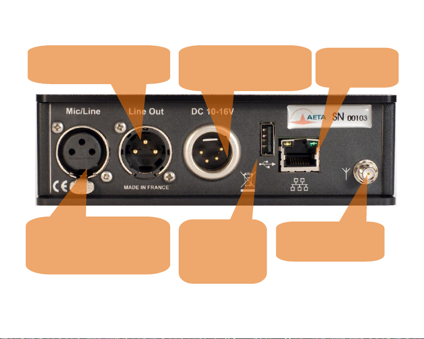
Rear side panel –Ethernet version
Mic/Line IN: balanced analog
adjustable gain from 0 to 48 dB
by16dB steps.
Max acceptable level: +19 dBu,
+48V powering available.
Main Antenna: SMA
connector to connect the
antenna
Line OUT: 3 pins XLR balanced
output. Level adjustment via Menu
USB A: USB1.1
Interface for
firmware updates
and import phone
book
Ethernet: RJ45
10/100Mbits/s
DC Power: XLR 4 for external
additional DC power 10 -16 V.
Can also be used for connecting
an AC/DC adaptor

13
Rear side panel –Contact version
SUBD9 GPIO :
Pin
Pin
Remark
Contact 1
(isolated)
2
6
Ex. Pin 2 : +5v /
Pin6 : Ground
Contact 2
7
Ground
Ex : Pin7 : +5v
Relais 1
4
8
Dry loop
Relais 2
5
9
Dry loop
Power +5V
1
Ground
3
GPIO: SubD 9pins with 2
relais, 2 contacts and power.

14
Web interface –Version ScoopFone Ethernet

15
Import
You can import a phonebook in your ScoopFone via a USB stick
You should put a "book-scoopfone.txt" file in the root of the USB drive and plug it
into the ScoopFone once started.
The file must have the following format:
Memory number: phone number
Ex:
1:0141361268
2:0141361279
Note: All memories will be set or erased

Table of contents
Other AETA Conference System manuals

Popular Conference System manuals by other brands


Multi-Voice Radio
Multi-Voice Radio MVR900 user guide

Avaya
Avaya Scopia Elite 6000 MCU Series Rack Mounting Guide

Cisco
Cisco TelePresence Profile Series Quick reference guide

Crestron
Crestron UC-MX50-Z-UPGRD quick start

Poly
Poly Large Room Kit setup sheet

Polycom
Polycom HDX 7000 Series Quick reference guide


