AETOOL OBDII User manual

AETOOL.com OBDII Scantool Manual

- 1 -
2%',,6&$1722/86(5·6
0$18$/
Table of Contents
1.0 -The
S
c
a
n
To
ol
---
----
----
------
----
----
------
----
----
------
----
----
------
----
----
------
-
1.1 Main Unit ------------------------------------------------------------------------------------------------------------------ 2
1.2 Keypad Functions --------------------------------------------------------------------------------------------------- 3
1.3 Settings: Adjustments -------------------------------------------------------------------------------------------- 4-5
1.4 About ------------------------------------------------------------------------------------------------------------------------- 5
2.0 -Vehicle Diagnosis-------------------------------------------------------------------------------
2.1 START SCANNING------------------------------------------------------------------------------------------------ 5-8
2.1.1 - READ DTCs------------------------------------------------------------------------------------------------- 8
2.1.2 - ERASE DTCs----------------------------------------------------------------------------------------------- 9-10
2.1.3 - LIVE DATA---------------------------------------------------------------------------------------------------- 11
2.1.4 - FREEZE FRAME DATA------------------------------------------------------------------------------ 11
2.1.5 - MIL STATUS ------------------------------------------------------------------------------------------------ 12
2.1.6 - I/M READINESS------------------------------------------------------------------------------------------ 13
2.1.7 - VEHICLE INFORMATION (VIN)--------------------------------------------------------------- 15
2.2 LAST CODES --------------------------------------------------------------------------------------------------------- 16
2.3 Select M.F (Select Manufacturer) ----------------------------------------------------------------------- 18
3
.0
–
Notic
e-------------------------------------------------
-
-----
---
----
----
-----
---
----
----
-----
3.1 Disclaimer ----------------------------------------------------------------------------------------------------------------20
4.0
– Warranty
Information--
--
--
--
--
--
--
--
--
---
--
--
--
--
--
---
--
--
--
--
--
---
--
--
--
--
--
---
-
4.1 Limited Warranty----------------------------------------------------------------------------------------------------- 20
4.2 Limitations of Warranty-------------------------------------------------------------------------------------------21
- 1 -
$(722/FRP 2 % ' ,,6&$172 2 / - 1 -

- 2 -
1.0 - The Scan Tool
1.1 - Main unit
Diagnostic Cable
DB15 Connector
Display
Keypad
- 2 - 2%',,6&$172 2 /

- 3 -
2%',,6&$1722/86(5·6
0$18$/
1.2 - Keypad Functions:
‘PWR’ key to start operation.
.
ENTER
ESC
HELP
‘ENTER’ key to confirm selection.
‘ESC’ key to exit and return to previous display.
HELP’ key for abbreviation query or info.
Page Up key for ‘next’ or scroll up
Page Down key for ‘previous’ or scroll down
- 3 -
$(722/FRP 2 % ' ,,6&$172 2 / - 3 -

- 4 -
1.3 - Settings: Adjustments
To enter the MENU Mode:
1、 Once the Scan Tool is powered up through the DLC
connection, the LCD screen lights up without any display.
Press key will wake up the display as below.
Note:
This is a safety feature that protects the scan tool from
power surge when plugged into the vehicles DLC.
2、 Press any key, it will switch to: “Car Manufacturer Logo “
3、 Press ENTER OR ESC key, the screen will enter
into: “New Scan” icon
4、Press key, to select: “Setting” icon as shown:
5、 Press ENTER key, the screen will enter into:
“Adjust Brightness” icon
6、 Press or key to increase or decrease the LCD Brightness
Contrast ranges from 1 to 10.
- 4 - 2%',,6&$172 2 /

- 5 -
2%',,6&$1722/86(5·6
0$18$/
7、 Once the brightness adjustment had been selected
to the desired setting, press
ENTER key to confirm
and exit back to the sub menu.
8、Press
ESC key to exit back to the main Menu.
1.4 - About
Enter the Setting Menu, press
confirm. ENTER key to
The screen will change to shown:
Press or key to select ‘About’ icon.
2.0 - Vehicle Diagnosis
2.1 - START SCANNING
- 5 - When everything had been confirmed and checked as mentioned in Getting Started, the
testing operation can be carried out.
$(722/FRP 2 % ' ,,6&$172 2 / - 5 -

- 6 -
1. Locate the vehicle Diagnostic Link Connector (DLC)
and make sure that the ignition switch is in OFF
position.
2. Connect the scan tool diagnostic connector to the
vehicle DLC.
If problem of inserting, rotate it to 180°
and try again
When the connection has been established, the LCD screen
lights up without any display.
Press key will wake up the display screen as
shown.
3. Press any key on the keypad will enter to select Car
Manufacturer logo as shown.
Now you can select the car manufacturer by pressing
the or key.
Press ENTER key to confirm and it will enter to the
screen as shown.
Now it is ready to do the scanning process if the
‘ENTER’ key is press again.
- 6 -
2%',,6&$172 2 /

- 7 -
2%',,6&$1722/86(5·6
0$18$/
4. If the car manufacturer logo is not correct and you
need to change it, then press or
key until icon.
Press ENTER key to enter; it will change back
to the car manufacturer logo.
Once the selection is confirmed, press this key again and it will return to the main
Menu.
7. To get ready for the scanning, use or
key to scroll to the ‘New Scan’ icon on the main Menu.
8. Turn the ignition key to ON. DO NOT start or crank
the engine.
9. Press the ENTER key once, the Scan tool will automatically starts to link up to the
- 7 -
vehicle’s computer and detects which type of communication protocol it is using.
10. After a few seconds, the screen will display the
menus as shown.
$(72 2 /FRP 2 % ' ,,6&$1722/ - 7 -

- 8 -
11. Now you can select the program from the menu by pressing or
key and confirm by ENTER key.
12. If the Scan tool fails to link up with the vehicle’s
computer, it will show a message as displayed on
the LCD screen:
Possible causes:
1. The Diagnostic connector is not connected properly.
2. Ignition Key is not turned ON.
3. The vehicle is not OBDII compliant.
Note:
To check whether the vehicle being tested is OBDII compliant, always
refer to the Vehicle Emission Control Information (VECI) decal located
under the
hood or by the radiator of most vehicles. See below).
2.1.1 – READ DTCs
✓ Selecting this function allows the Scan Tool to read the DTCs
from the vehicle’s control modules. DTCs are used to help
determine the
cause of a problem or problems within a vehicle. These codes cause the
control module to illuminate the malfunction indicator lamp
(MIL) when emission-related or drivability fault occurs. MIL
is also known as service engine soon or check engine lamp.
✓ READ DTCs can be done with the Key On Engine Off (KOEO)
or with the Key On Engine Running (KOER).

- 8 - 2%',,6&$172 2 /

- 9 -
2%',,6&$1722/86(5·6
0$18$/
On the ‘Read DTCs’ icon, pressing ENTER
key will proceed to display the DTC (P0001) and
its definition as shown in this example.
If there are more than one DTCs, press
or key will proceed to the next DTC.
Press ENTER
key to view more
help information as shown:
To Exit this function, press ESC key
will return back to the previous screen.
2.1.2 - ERASE DTCs
Selecting this function erases the DTCs from vehicle’s control module(s)
memory. Perform this function with KOEO. Do not start the engine.
- 9 - ✓ The ERASE DTCs function may also erase Freeze Frame Data......
✓ The ERASE DTCs function resets all the I/M Readiness Monitor Status
to a not RUN “flashing” condition. To set all of the Monitors to a DONE
status, an OBDII Drive Cycle must be performed. Please refer to the
$(722/FRP 2 % ' ,,6&$172 2 / - 9 -

ENTER
ENTER
ENTER
- 10 -
vehicle service manual for information on how to perform an OBDII Drive
Cycle for the vehicle under test.
Note:
If the tested vehicle has DTC present in its memory and need to be
sent to the workshop for repair. Do not use this function to erase it.
These DTC will help the technicians to troubleshoot the engine
problem encountered.
Perform ERASE DTCs function only when the vehicle had been
repaired.
To start this function, go back to the ‘New Scan’
menu and select the icon as shown by pressing
the or key.
Press
the
ENTER key, the screen will display
message as shown:
To Erase DTC press
otherwise ENTER key
press
When
ESC
ENTER
key.
ENTER
key was pressed, the
screen will display the message as shown, if it
has successfully erased the DTCs.
To Exit this function, press ESC key will
return back to the previous screen.
- 10 - 2%',,6&$172 2 /

ENTER
- 11 -
2%',,6&$1722/86(5·6
0$18$/
2.1.3 - LIVE DATA
The LIVE DATA function allows real time viewing of the vehicles computer
module’s PID data. As the computer monitors the vehicle, information is
simultaneously transmitted to scan tool.
To start this function, go to ‘New Scan’ Menu and
select ‘Live Data’ icon as shown:
Press key, the screen will change to:
ENTER
Use the and arrow keys to view
other sensors.
HELP
If key is pressed, it will display the
definitions of the selected sensor.
To Exit this function, press
screen ESC key will return back to the previous
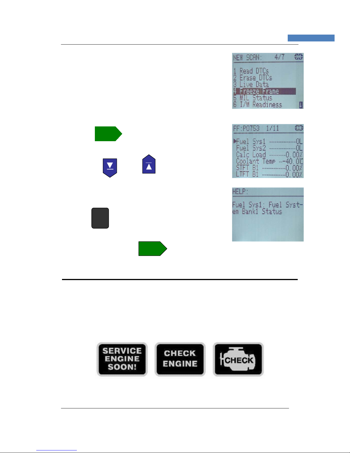
2.1.4 - FREEZE FRAME
- 11 -
When an emission-related fault has occurs, certain vehicle conditions are recorded
by the on-board computer. This information is referred to as Freeze Frame data.
FREEZE FRAME is a snapshot of the operating conditions at the time of an
emission-related fault had occurred.
✓
FREEZE FRAME can be overwritten by faults with a higher priority.
✓ If DTCs were erased, FREEZE FRAME may not be stored in vehicle
memory depending on vehicle.
$(722/FRP 2 % ' ,,6&$172 2 / - 11 -
ENTER
- 12 -
To access to this function, go to ‘New Scan’ Menu and
select Freeze Frame icon:
Press
Freeze
ENTER key the screen will display the
Frame data as shown.
Use the and arrow keys to
view
other sensors.
Press HELP key to view more information about
the selected sensor.
To Exit this function, press
ENTER key will return back to the previous screen.
2.1.5 - MIL STATUS
When the vehicle on board computer detects a problem in the emission related
systems or components, its diagnostic program will assign a fault code (DTC) and
store it in its memory. It also records a “Freeze Frame” of the conditions present
when the fault was found and set the Malfunction Indicator Lamp (MIL) alight. Some
faults require detection for two trips in a row before the MIL is turned on.
Three typical examples of MIL are shown below:
- 12 - 2%',,6&$1722/

- 13 -
2%',,6&$1722/86(5·6
0$18$/
Definition of Trip
‘A Trip’ is define as a Key-ON, Key-OFF event in which the power-train control
module (PCM) detects the following:
o
• Engine coolant temperature should exceed 70 C
o
• Engine coolant temperature should change more than 20 C after starting the
engine.
• Engine speed should go over 400 RPM.
st
When the power-train control module (PCM) detects a fault during the 1 trip, the
DTC and the corresponding ‘Freeze Frame’ data are stored in the PCM’s memory.
nd
The MIL will not light up until the fault is again detected during the 2 trip. Certain
DTCs are capable of turning the Malfunction Indicator Light (MIL) ‘ON’ or ‘blinking’
during the first trip.
To access to this function, go to ‘New Scan’ Menu and
select MIL Status icon:
ENTER
Press key, the screen will display as shown:
If there is no fault in the system, then
the screen will display as shown:
2.1.6 - I/M Readiness
The I/M Readiness (Inspection / Maintenance Readiness) function is used to
view a snapshot of the operations on the emission system on OBD II vehicles.
✓ I/M Readiness is a very useful function. To guarantee no faults exist and to
make sure all monitors are okay or not present and no DTCs exist.
- 13 - ✓ Always refer to the vehicles service manual for the Drive Cycle operation.
✓ During normal driving conditions, the vehicle’s computer scans the
Emission system. After a specific amount of drive time (each monitor
has specific driving conditions and time required), the computer’s
$(722/FRP 2 % ' ,,6&$172 2 / - 13 -

Abbreviation Full Description
- MIS Misfire Monitor
- FUE Fuel System Monitor
- CCM Comprehensive Components Monitor
- CAT Catalyst Monitor
- HCA Heated Catalyst Monitor
- EVA Evaporative System Monitor
- AIR Secondary Air System Monitor
- ACR Air Conditioning Refrigerant Monitor
- O2S Oxygen Sensor Monitor
- HTR Oxygen Sensor Heater Monitor
- EGR Exhaust Gas Recirculation System Monitor
- 14 -
monitors decide if the vehicles emission system is working correctly
or not as well as detecting out of range values. When the monitor’s
status is:
• Has Run - vehicle was driven enough to complete the monitor.
• Has Not Run - vehicle was not driven enough to complete the
monitor.
• Don’t support- vehicle does not support that monitor.
✓ Depending on the vehicle, disconnecting or a discharged battery may
erase DTCs and clear monitor status.
✓ Monitors may be cleared by:
❒ Erasing DTCs
❒ Vehicle control modules losing power
✓ I/M Readiness Monitor Status can be done with the KOER or KOEO.
Abbreviations and Descriptions for OBD II Monitors supported by the Scan
Tool is given below. They are required by the United States Environmental
Protection Agency (EPA). Not all monitors are supported by all vehicles.
- 14 -
To access to this function, go to ‘New Scan’ Menu
and select I/M Readiness icon:
2%',,6&$172 2 /

- 15 -
2%',,6&$1722/86(5·6
0$18$/
Press
ENTER key will enter this function and the
screen will display as shown:
HELP
Press key to view more information on
the Monitors as shown:
Note:
As indicated on the above HELP information, the sensors marked with
black background and white wordings [Has Run]. Those with black
wordings [Has Not Run]. The shaded wordings indicated that they
were not present or supported.
Use the and keys to scroll for more
information.
To Exit this function, press
display screen.
ENTER key will return back to the previous
2.1.7 – Vehicle Information (VIN
)
This Vehicle Information (VIN) function allows the Scan Tool to request the
vehicle’s VIN number, calibration ID(s) which identifies software version in
vehicle control module(s), and calibration verification numbers (CVN(s).)
- 15 - ✓ Vehicle Information (VIN) function applies to model year 2000 and newer
OBD II compliant vehicles.
✓ The Scan Tool cannot verify if data is correct for scanned vehicles.
$(722/FRP 2 % ' ,,6&$172 2 / - 15 -

- 16 -
✓ CVNs are calculated values required by OBD II regulations.
✓ The CVN calculation may take several minutes.
✓ CVNs are reported to determine if emission-related calibrations have been
changed. Multiple CVNs may be reported for a control module.
To access to this function, go to ‘New Scan’ Menu and
select VIN icon:
Press ENTER key, the display will show the
Vehicle Information
Use the and keys to view more
information:
2.2.0 - LAST CODES:
The Scan Tool will automatically save the last tested communication protocol and car
model, which will be used for the next subsequent test on the same vehicle until
changing is done by the next vehicle.
The Scan Tool also auto save the last test results to its memory until next test
covering, which could easy review the history data before proceeding to next test.
Auto saving items:
Last DTCs
Last Freeze Frame
Last MIL Status
Last I/M Readiness
Last VIN (Vehicle info)
- 16 - 2%',,6&$172 2 /

ENTER
ENTER
- 17 -
2%',,6&$1722/86(5·6
0$18$/
To enter into this function, go to the Main Menu,
Select LAST CODES:
Press ENTER key, the screen will display the
menu as shown:
Press ENTER key again will enter into the program
and displays the last tested vehicle DTCs readings.
To Exit this function, press ESC key will return
back to the previous display screen.
Use the and keys to select the
required subsequent programs listed in the menu.
To view Last Freeze Frame data, select the F.F icon
as shown and press ENTER key.
- 17 -
To view Last MIL Status, select the MIL icon as
shown and press ENTER key.
$(722/FRP 2 % ' ,,6&$172 2 / - 17 -

To view Last I/M Readiness, select IM icon as
- 18 -
shown and press ENTER key.
To view Last Vehicle info, select the VIN icon as
shown and press ENTER key.
2.3.0 - Select M.F (Manufacturer)
Vehicle Manufacturer specific codes are non-uniform DTCs. Areas within each alpha
designator have been made available for manufacturer-controlled DTCs such as
P1xxx, P30xx, U1xxx, etc. These are fault codes (DTCs) that will not generally be
used by a majority of the manufacturers due to basic system differences,
implementation differences, or diagnostic strategy differences.
Each vehicle manufacturer or supplier who designs and specifies diagnostic
algorithms, software, and diagnostic trouble codes are strongly encouraged to remain
consistent across their product line when assigning codes in the manufacturer
controlled area.
For powertrain codes, the same groupings should be used as in the ISO /SAE
controlled area, i.e. 100's and 200's for fuel and air metering, 300's for ignition system
or misfire, etc.
Code groupings for non-powertrain codes will be specified at a later date.
While each manufacturer has the ability to define the controlled DTCs to meet their
specific controller algorithms, all DTC words shall meet ISO 15031-2.
Note:
Correct selection of the Manufacturer on which the vehicle being tested will provide
more information in the HELP mode.
To enter the MENU Mode:
Once it is powered up through the DLC connection,
press key, the wake up screen will display
as shown
- 18 - 2%',,6&$1722/
Table of contents
Other AETOOL Measuring Instrument manuals


